EP0950730A2 - A system for galvanic treatment or finishing of pieces, and corresponding method - Google Patents
A system for galvanic treatment or finishing of pieces, and corresponding method Download PDFInfo
- Publication number
- EP0950730A2 EP0950730A2 EP99106307A EP99106307A EP0950730A2 EP 0950730 A2 EP0950730 A2 EP 0950730A2 EP 99106307 A EP99106307 A EP 99106307A EP 99106307 A EP99106307 A EP 99106307A EP 0950730 A2 EP0950730 A2 EP 0950730A2
- Authority
- EP
- European Patent Office
- Prior art keywords
- bath
- barrel
- treatment
- washing liquid
- baths
- Prior art date
- Legal status (The legal status is an assumption and is not a legal conclusion. Google has not performed a legal analysis and makes no representation as to the accuracy of the status listed.)
- Granted
Links
Images


Classifications
-
- B—PERFORMING OPERATIONS; TRANSPORTING
- B65—CONVEYING; PACKING; STORING; HANDLING THIN OR FILAMENTARY MATERIAL
- B65G—TRANSPORT OR STORAGE DEVICES, e.g. CONVEYORS FOR LOADING OR TIPPING, SHOP CONVEYOR SYSTEMS OR PNEUMATIC TUBE CONVEYORS
- B65G49/00—Conveying systems characterised by their application for specified purposes not otherwise provided for
- B65G49/02—Conveying systems characterised by their application for specified purposes not otherwise provided for for conveying workpieces through baths of liquid
- B65G49/04—Conveying systems characterised by their application for specified purposes not otherwise provided for for conveying workpieces through baths of liquid the workpieces being immersed and withdrawn by movement in a vertical direction
- B65G49/0409—Conveying systems characterised by their application for specified purposes not otherwise provided for for conveying workpieces through baths of liquid the workpieces being immersed and withdrawn by movement in a vertical direction specially adapted for workpieces of definite length
- B65G49/0436—Conveying systems characterised by their application for specified purposes not otherwise provided for for conveying workpieces through baths of liquid the workpieces being immersed and withdrawn by movement in a vertical direction specially adapted for workpieces of definite length arrangements for conveyance from bath to bath
- B65G49/044—Conveying systems characterised by their application for specified purposes not otherwise provided for for conveying workpieces through baths of liquid the workpieces being immersed and withdrawn by movement in a vertical direction specially adapted for workpieces of definite length arrangements for conveyance from bath to bath along a continuous circuit
- B65G49/045—Conveying systems characterised by their application for specified purposes not otherwise provided for for conveying workpieces through baths of liquid the workpieces being immersed and withdrawn by movement in a vertical direction specially adapted for workpieces of definite length arrangements for conveyance from bath to bath along a continuous circuit the circuit being fixed
- B65G49/0454—Conveying systems characterised by their application for specified purposes not otherwise provided for for conveying workpieces through baths of liquid the workpieces being immersed and withdrawn by movement in a vertical direction specially adapted for workpieces of definite length arrangements for conveyance from bath to bath along a continuous circuit the circuit being fixed by means of containers -or workpieces- carriers
-
- C—CHEMISTRY; METALLURGY
- C25—ELECTROLYTIC OR ELECTROPHORETIC PROCESSES; APPARATUS THEREFOR
- C25D—PROCESSES FOR THE ELECTROLYTIC OR ELECTROPHORETIC PRODUCTION OF COATINGS; ELECTROFORMING; APPARATUS THEREFOR
- C25D17/00—Constructional parts, or assemblies thereof, of cells for electrolytic coating
- C25D17/16—Apparatus for electrolytic coating of small objects in bulk
- C25D17/18—Apparatus for electrolytic coating of small objects in bulk having closed containers
- C25D17/20—Horizontal barrels
Definitions
- the present invention concerns the plating and finishing of metal pieces immersed in a bath and in particular concerns an improved system for galvanic coating or finishing treatments on metal pieces, and in particular small metal items.
- the pieces are loaded into tumbling barrels, or "tumblers", having a cylindrical or prismatic shape and set with the axis horizontal, the said barrels having perforated walls and an openable door.
- tumblers having a cylindrical or prismatic shape and set with the axis horizontal, the said barrels having perforated walls and an openable door.
- Each barrel is carried on a supporting frame and is free to turn about its own axis.
- the system comprises a set of baths arranged in a line, in which the frame-and-barrel assemblies loaded with the pieces to be treated are immersed.
- a particular stage of the treatment or a stage preliminary to the treatment is carried out, such as washing, degreasing, pickling, de-activation, and zinc coating (galvanization).
- a number of barrels are treated simultaneously in the same bath.
- the barrels are set side by side in each bath in a stationary position, and each barrel is moved from one bath to the subsequent one by means of an overhead travelling crane, which lifts it up, displaces it according to a direction referred to as direction of advance, and lowers it into the new position.
- the direction of advance and the direction defined by the axes of the barrels are usually orthogonal with respect to one another.
- anodic bars are set transversely with respect to the baths and parallel to the axes of the barrels, between adjacent barrels, and this reduces the quality of the treatment.
- an anodic bar is shared between two adjacent tumblers produces the undesirable effect of conveying the greater number of cations, and hence more metal, towards the tumbler that presents higher conductivity, at the expense of the other tumbler.
- replacement of the anodic bars is particularly inconvenient and dangerous, since the operator in charge must climb onto the baths to carry out periodic replacement.
- control of the current is carried out by placing a current rectifier for each position of electrolytic plating, with an enormous economic expenditure owing to the number of connections and the number of current generators required for electrolytic processes.
- the purpose of the present invention is to provide a system for the treatment of pieces that is able to overcome the drawbacks referred to above, and in particular, to prevent dripping of the barrels during their transportation from one bath to another, or rather to prevent the dripping of substances into baths in which the presence of these substances is undesirable.
- the invention achieves the purposes set, i.e., prevents dripping of the barrels during their progress through the cycle, reduces the times of transportation of the barrels during their progress, prevents discontinuity and unevenness of treatment, facilitates periodic replacement of the anodic bars, enables installation of suction hoods over a wide area of the treatment baths (in that it is not necessary for the overhead travelling crane to have access to the entire extent of the treatment baths), and simplifies the connections for the current required for the electrolytic processes.
- a system 10 comprises a set of baths V arranged in longitudinal succession, preferably along two parallel lines. In each bath, one treatment or one treatment stage is performed.
- the baths V 1 , V 2 , V 3 are on one branch of the system; the bath V 4 is on the other branch of the system.
- a number of positions inside one bath, destined to be occupied by barrel assemblies, are defined by rectangles and indicated by P 1,1 , P 1,2 , P 1,3 for the bath V 1 , P 2,1 , P 2,2 , etc., for the bath V 2 , and so forth.
- a direction of advance according to the arrow A, from left to right, is defined for the branch of system appearing at the top of the drawing, and according to the arrow B, from right to left, for the branch appearing at the bottom of the drawing.
- the two branches are connected at one end, on the right in the figure, by a transfer device, 11, and the second branch presents, at the opposite end, a discharging device 13.
- the bath V 1 can accept, for example, three barrel assemblies, in positions P 1,1 , P 1,2 , and P 1,3 . At least some of the baths of the system are equipped with a pusher device which will be described later.
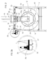
- a barrel or tumbler assembly 12 comprises a tumbling barrel or tumbler 14 supported so that it is free to turn about a horizontal axis 15, carried by a structure or frame 28.
- the tumbler 14, in a per se known way, comprises a body 17 generally having a polygonal profile, with perforated walls 19. One, 19a, of the walls is hinged to the adjacent wall to serve as a door.
- the bases of the prism made up by the walls also consist of plane perforated walls mounted on the axis 15 so that they are free to turn.
- the body is fixed to a gear wheel 41, which meshes with an intermediate wheel 42, driven by a pinion 44, mounted on the output shaft of a motor 20 for turning the barrel.
- the motor 20 is carried on the frame 28 of the barrel assembly.
- the supporting frame 28 has opposite axles preferably aligned according to axes contained in planes orthogonal to the axis 15.
- the axles 30 carry at their distal ends idle wheels 26, which are electrically conducting.
- each frame comprises two pairs of axles and two pairs of wheels 26.
- Each frame also presents, on one of its sides, current-drawing arms 34, which terminate in slides 35 provided with cathodic contact 36.
- the barrel-supporting frame 28 further has hook-like parts 18 designed to be hooked by a hooking means 21 of an overhead travelling crane 16.
- the frame structure of each barrel assembly has a leading wall and a trailing wall which are parallel and are indicated by 28a and 28b.
- the current-drawing arms 24, through a cathode contact pad 36, conduct treatment current to a current-drawing or current supplier device 38 extending inside the barrel, which transmits polarization current to the metal items contained in the barrel.
- the conductive idle wheels 26, on the other hand, transmit supply current to the motor 20.
- the bath V is equipped with a first conducting rail 39 for cathodic current and a second conducting rail, set alongside the first and insulated from it, indicated by 37, for the current supplying the motor.
- a first conducting rail 39 for cathodic current for cathodic current
- a second conducting rail set alongside the first and insulated from it, indicated by 37, for the current supplying the motor.
- the wheels 26 make contact on one side, possibly via copper rods 7.
- the cathodic contact pad 36 makes contact.
- the anodic bars 24 are arranged longitudinally along the bath.
- the bottom of the bath V indicated by 49, has a semicircular shape, concentric to the axis 15 of the tumbler and with a radius greater than the said tumbler, so as to have an "enveloping" shape, at least in the part below the position of the said axis 15.
- one at least of the baths V of the system is equipped with a pusher device 50.
- FIG 1 four pusher devices are indicated, i.e., 50 1 for the bath V 1 , 50 2 for the bath V 2 , 50 3 for the bath V 3 , and 50 4 for the bath V 4 .
- a generic pusher 50 is described with reference to Figures 3 and 5.
- the pusher device basically comprises a transverse bar 51 which moves alternately forwards and backwards along the bath for a stroke corresponding to the length of at least one tumbler assembly.
- the pusher bar 51 is set at a height such that it can engage the rear transverse bars 28b of the tumbler frame 28.
- the alternating movement of pushing forward and return of the bar 51 of the pusher can be obtained in any known way.
- the bar 51 is mounted on two chains 53, 53, carried at the sides of the bath and moved around gear wheels 54, 56.
- a washing station will be described which constitutes a characteristic of an embodiment of the system.
- a barrel assembly 12 is illustrated inside a washing bath VL provided with a "semi-enveloping" bottom, as has been explained above with reference to the treatment baths.
- the bath VL has a filler inlet 61 and a discharge outlet 62 connected to a suction pump 63.
- a washing tower is indicated by TL and comprises three tanks L 1 , L 2 , L 3 set one above the other.
- the top tank L 3 contains the cleanest washing liquid and has an overflow 64 leading towards the intermediate tank.
- the intermediate tank L 2 contains less clean washing liquid and has an overflow 64 leading towards the bottom tank.
- the bottom tank L 1 contains the dirtiest liquid and has an overflow 65 leading towards the discharge.
- the reference 66 indicates a delivery pump, and 67 a return pump. Washing is carried out first with the liquid from the tank L 1 , then with the liquid from the tank L 2 , and finally with the liquid from the tank L 3 .
- the enveloping bottom of the bath enables maximum use of the washing liquid without unused spaces.
- the process can be carried out in only one direction, either clockwise or counterclockwise, without any reversing. Consequently, in the various stages of the process, the overhead travelling crane just transfers the barrels in the direction of the process and always comes back empty. What has been said above does not rule out the possibility, in cases of particular interest, so as to save space, of reversing the direction of advance during the transportation stage and of carrying out more than one operation in the same bath; for example, washing of a basket in running water, subsequent transfer to another stage, return to the washing stage with reversal of direction of movement.
Landscapes
- Chemical & Material Sciences (AREA)
- Organic Chemistry (AREA)
- Chemical Kinetics & Catalysis (AREA)
- Electrochemistry (AREA)
- Materials Engineering (AREA)
- Metallurgy (AREA)
- Engineering & Computer Science (AREA)
- Electroplating Methods And Accessories (AREA)
- Electroplating And Plating Baths Therefor (AREA)
- Chemical Treatment Of Metals (AREA)
- Gripping Jigs, Holding Jigs, And Positioning Jigs (AREA)
- Coating By Spraying Or Casting (AREA)
- Cleaning By Liquid Or Steam (AREA)
- Chemical And Physical Treatments For Wood And The Like (AREA)
- Electrical Discharge Machining, Electrochemical Machining, And Combined Machining (AREA)
Abstract
Description
Claims (20)
- A system for treatment of pieces in a bath, e.g a galvanic treatment or a finishing treatment of small metal items, in which the pieces undergo the treatment contained in tumbling barrels having perforated walls and being set with their axes horizontal, the said system comprising treatment baths arranged in succession, at least one direction of advance of the barrels in the system being defined,
characterized in thata number of the said barrels (14) in a bath are arranged with their axes of rotation substantially aligned longitudinally according to the direction of advance. - A system according to Claim 1, in which the said direction of advance is the longitudinal direction of the bath.
- A system according to Claim 1, characterized in that it comprises a pusher device (50) in at least one of the said baths, the said pusher device comprising a pushing member movable for a stroke at least equal to the length of a said barrel.
- A system according to Claim 1, characterized in that at least one said barrel (14) is carried on a supporting frame, forming with it a barrel assembly, and the said frame comprises sliding and supporting means for sliding or running engagement on rails set longitudinally along the bath.
- A system according to Claim 4, characterized in that the said sliding/running means are idle wheels (26), at least one of the said wheels being electrically conductive, and in that the said bath has a conductive longitudinal rail (37) for contact with the said at least one conductive wheel.
- A system according to Claim 3, characterized in that the said frame has at least one arm extending laterally and carrying a contact pad (36), and further has a cathodic current-drawing device (38) in electrical continuity with the said first pad and extending inside the barrel, and the said bath has, on at least one longitudinal side of the same, a cathodic longitudinal contact (39) for contact with the said pad (36).
- A system according to Claims 4 and 5, in which the said current-drawing rail (37) and the said cathodic contact rail (39) are parallel and set on the same side of the bath.
- A system according to Claim 1, characterized in that the anodic bars (24) are set longitudinally along at least one bath on at least one side of the latter.
- A system according to Claim 3, characterized in that the said pusher member is a bar (51) of the pusher, to which movement is imparted via a chain system, the chains (53) being located at the sides of the bath.
- A system according to Claim 1, comprising suction hoods which substantially cover the entire transverse extension of the bath for a longitudinal stretch of the bath corresponding to one or more barrel lengths.
- A system according to Claim 1, further comprising lifting means (16) for lifting up a barrel assembly at a downstream end of a bath and depositing it at an upstream end of the subsequent bath.
- A system according to Claim 11, characterized in that the said means is an overhead travelling crane (16), and each tumbler structure comprises means (18) for being hooked by the overhead travelling crane.
- A system according to any one of the previous claims, characterized in that at least one of the said baths is shaped so as to have a semi-cylindrical bottom (49) having a radius greater than the maximum radius of the barrel.
- A system according to any one of the previous claims, characterized in that it comprises a washing station (VL) with a number of tanks (L1, L2, L3) set in tower fashion and containing washing liquid with different percentages of impurities and means for taking the washing liquid from the said tanks and introducing it into the washing bath and discharging it into the respective tank.
- A system according to any one of the previous claims, characterized in that it comprises an even number of lines, and at the end of one line at least one barrel is transferred to the subsequent line which is traversed in the direction opposite to the previous line.
- A system according to any one of the previous claims, characterized in that it comprises tunnel-type suction means.
- A method for the treatment of pieces in treatment baths arranged in succession, the pieces being loaded into tumbling barrels which are made to advance along the said baths, characterized in thatthe said tumbling barrels are arranged in the said baths with their axes of rotation aligned to the longitudinal axis of the bath and are made to advance longitudinally inside the said bath with a displacement according to their longitudinal axis.
- A method according to Claim 17, characterized in that it comprises the stages of lifting a said barrel from a downstream position in a first bath, translating it and lowering it into an upstream position in an immediately subsequent bath.
- A method according to Claim 17, comprising a washing stage, characterized in that it comprises the operations of taking a first quantity of washing liquid from a first tank, washing the pieces with the said washing liquid of the said first tank, and discharging the said used washing liquid into a storage container or a container for subsequent treatment; taking a second quantity of washing liquid from a second tank, washing with the said washing liquid of the said second tank the pieces already washed, and discharging the used washing liquid into a container for subsequent use as first-washing liquid.
- A method according to Claim 17, comprising the stage of picking up a barrel at the end of a treatment line, bringing it to the beginning of the subsequent line and cause the latter to be traversed in a direction opposite to that of the first treatment line.
Applications Claiming Priority (4)
| Application Number | Priority Date | Filing Date | Title |
|---|---|---|---|
| IT98MI000683A IT1298983B1 (en) | 1998-03-31 | 1998-03-31 | GALVANIC PLANT FOR PIECE PLATING |
| ITMI980683 | 1998-03-31 | ||
| CA002278862A CA2278862A1 (en) | 1998-03-31 | 1999-07-27 | A system for galvanic treatment or finishing of pieces, and corresponding method |
| US09/363,037 US6537430B1 (en) | 1998-03-31 | 1999-07-29 | System for galvanic treatment or finishing of pieces, and corresponding method |
Publications (3)
| Publication Number | Publication Date |
|---|---|
| EP0950730A2 true EP0950730A2 (en) | 1999-10-20 |
| EP0950730A3 EP0950730A3 (en) | 2002-06-05 |
| EP0950730B1 EP0950730B1 (en) | 2006-08-23 |
Family
ID=27170994
Family Applications (1)
| Application Number | Title | Priority Date | Filing Date |
|---|---|---|---|
| EP99106307A Expired - Lifetime EP0950730B1 (en) | 1998-03-31 | 1999-03-26 | A system for galvanic treatment or finishing of pieces, and corresponding method |
Country Status (8)
| Country | Link |
|---|---|
| US (1) | US6537430B1 (en) |
| EP (1) | EP0950730B1 (en) |
| AT (1) | ATE337420T1 (en) |
| CA (1) | CA2278862A1 (en) |
| DE (1) | DE69932877T2 (en) |
| ES (1) | ES2272023T3 (en) |
| IT (1) | IT1298983B1 (en) |
| SI (1) | SI0950730T1 (en) |
Cited By (2)
| Publication number | Priority date | Publication date | Assignee | Title |
|---|---|---|---|---|
| EP2000564A1 (en) | 2007-06-06 | 2008-12-10 | C. Uyemura & Co., Ltd. | Workpiece surface treatment systems and methods |
| EP3912940A1 (en) * | 2020-05-18 | 2021-11-24 | ATOTECH Deutschland GmbH | Device and system for transporting a plurality of parts to be treated through an apparatus for wet-chemical treatment |
Families Citing this family (2)
| Publication number | Priority date | Publication date | Assignee | Title |
|---|---|---|---|---|
| US7416545B1 (en) * | 2000-08-07 | 2008-08-26 | The Procter & Gamble Company | Absorbent article with improved fastening system |
| CN109487191B (en) * | 2018-12-14 | 2020-10-02 | 浙江格力威机械股份有限公司 | Bolt hot galvanizing process |
Family Cites Families (15)
| Publication number | Priority date | Publication date | Assignee | Title |
|---|---|---|---|---|
| US1563041A (en) * | 1923-09-07 | 1925-11-24 | Forrest G Purinton | Electroplating apparatus |
| GB790006A (en) * | 1954-08-05 | 1958-01-29 | Udylite Res Corp | Apparatus for plating and/or chemical treatment of articles |
| US3099275A (en) * | 1961-04-24 | 1963-07-30 | Udylite Corp | Drain mechanism for barrel type conveying apparatus |
| US3444802A (en) * | 1967-02-23 | 1969-05-20 | Ionic International Inc | Forced air curtain wall for hoist and auxiliary equipment |
| US3444803A (en) | 1967-07-07 | 1969-05-20 | Cory Corp | Beverage brewer and dispenser |
| US3974057A (en) * | 1971-01-13 | 1976-08-10 | Hans Henig | Electro plating barrel |
| GB1583854A (en) * | 1976-02-28 | 1981-02-04 | Rigalster Ltd | Treatment of metal workpieces |
| JPS5810477B2 (en) * | 1978-12-22 | 1983-02-25 | 近藤耐酸槽株式会社 | automatic plating method |
| US4390399A (en) * | 1980-11-24 | 1983-06-28 | Mcinnes Robert | Method and apparatus for plating articles |
| US4422774A (en) * | 1981-03-20 | 1983-12-27 | The Harshaw Chemical Company | Metal finishing barrel apparatus |
| US4425212A (en) * | 1981-11-20 | 1984-01-10 | Francis William L | Electroplating device |
| US4769117A (en) * | 1986-05-02 | 1988-09-06 | Uyemura Kogyo Kabushiki Kaisha | Barrel plating apparatus |
| JPS63134420A (en) * | 1986-07-08 | 1988-06-07 | Nippon Denso Co Ltd | Transport device for container for processed article |
| JPS63310998A (en) * | 1987-06-13 | 1988-12-19 | Chuo Seisakusho:Kk | Barrel plating device |
| US5417829A (en) * | 1993-10-08 | 1995-05-23 | Tumbleveyor, Inc. | Apparatus for the surface treatment of parts |
-
1998
- 1998-03-31 IT IT98MI000683A patent/IT1298983B1/en active IP Right Grant
-
1999
- 1999-03-26 SI SI9930927T patent/SI0950730T1/en unknown
- 1999-03-26 EP EP99106307A patent/EP0950730B1/en not_active Expired - Lifetime
- 1999-03-26 ES ES99106307T patent/ES2272023T3/en not_active Expired - Lifetime
- 1999-03-26 AT AT99106307T patent/ATE337420T1/en active
- 1999-03-26 DE DE69932877T patent/DE69932877T2/en not_active Expired - Lifetime
- 1999-07-27 CA CA002278862A patent/CA2278862A1/en not_active Abandoned
- 1999-07-29 US US09/363,037 patent/US6537430B1/en not_active Expired - Fee Related
Cited By (6)
| Publication number | Priority date | Publication date | Assignee | Title |
|---|---|---|---|---|
| EP2000564A1 (en) | 2007-06-06 | 2008-12-10 | C. Uyemura & Co., Ltd. | Workpiece surface treatment systems and methods |
| US7938914B2 (en) | 2007-06-06 | 2011-05-10 | C. Uyemura & Co., Ltd. | Workpiece surface treatment system |
| CN101319345B (en) * | 2007-06-06 | 2011-07-27 | 上村工业株式会社 | Workpiece surface treatment system |
| US9242281B2 (en) | 2007-06-06 | 2016-01-26 | C. Uyemura & Co., Ltd. | Workpiece surface treatment system |
| EP3912940A1 (en) * | 2020-05-18 | 2021-11-24 | ATOTECH Deutschland GmbH | Device and system for transporting a plurality of parts to be treated through an apparatus for wet-chemical treatment |
| WO2021233938A1 (en) | 2020-05-18 | 2021-11-25 | Atotech Deutschland Gmbh | Device and system for transporting a plurality of parts to be treated through an apparatus for wet-chemical treatment |
Also Published As
| Publication number | Publication date |
|---|---|
| EP0950730B1 (en) | 2006-08-23 |
| ATE337420T1 (en) | 2006-09-15 |
| ES2272023T3 (en) | 2007-04-16 |
| SI0950730T1 (en) | 2007-04-30 |
| EP0950730A3 (en) | 2002-06-05 |
| IT1298983B1 (en) | 2000-02-07 |
| CA2278862A1 (en) | 2001-01-27 |
| US6537430B1 (en) | 2003-03-25 |
| DE69932877T2 (en) | 2007-04-05 |
| DE69932877D1 (en) | 2006-10-05 |
| ITMI980683A1 (en) | 1999-10-01 |
Similar Documents
| Publication | Publication Date | Title |
|---|---|---|
| CN1119436C (en) | Method and device for surface treatment of parts | |
| US5110440A (en) | Roll immersion system | |
| US4654089A (en) | Counterflow spray rinse process | |
| EP0950730B1 (en) | A system for galvanic treatment or finishing of pieces, and corresponding method | |
| US20140014523A1 (en) | Method of anodizing hollow metallic bodies | |
| US5985106A (en) | Continuous rack plater | |
| US5401379A (en) | Chrome plating process | |
| US4559122A (en) | Continuous-cycle electroplating plant | |
| US3945388A (en) | Apparatus for counterflow rinsing of workpieces | |
| HK1023151A (en) | A system for galvanic treatment or finishing of pieces, and corresponding method | |
| JP2015120952A (en) | Plating apparatus | |
| US3276983A (en) | Method and apparatus for movement of workpieces in a plating machine | |
| US20230024157A1 (en) | Coating system and electrode rack | |
| US1959764A (en) | Apparatus for plating | |
| US3278409A (en) | Electroplating machine | |
| KR100536133B1 (en) | Barrel type continuous plating device | |
| KR100326394B1 (en) | Ni-Cr FULL AUTOMATIC PLATING APPARATUS AND PLATING METHOD USING SAID APPARATUS | |
| JP2003147593A (en) | Basket type barrel and surface treatment equipment using basket type barrel | |
| CN222064639U (en) | Hot dip galvanization pretreatment processing line | |
| US3573187A (en) | Apparatus for processing articles | |
| US3200052A (en) | Method of and apparatus for plating loom drop wires | |
| USRE19560E (en) | Electroprocessing machine | |
| KR102057507B1 (en) | Plating system | |
| US2576998A (en) | Method of electroplating zinc | |
| BG4136U1 (en) | Technological line for drum zinc coating and rotating drum for drum unit on such technological line |
Legal Events
| Date | Code | Title | Description |
|---|---|---|---|
| PUAI | Public reference made under article 153(3) epc to a published international application that has entered the european phase |
Free format text: ORIGINAL CODE: 0009012 |
|
| AK | Designated contracting states |
Kind code of ref document: A2 Designated state(s): AT BE CH CY DE DK ES FI FR GB GR IE IT LI LU MC NL PT SE |
|
| AX | Request for extension of the european patent |
Free format text: AL;LT;LV;MK;RO;SI |
|
| RIC1 | Information provided on ipc code assigned before grant |
Free format text: 7C 25D 17/20 A, 7B 65G 49/04 B |
|
| PUAL | Search report despatched |
Free format text: ORIGINAL CODE: 0009013 |
|
| AK | Designated contracting states |
Kind code of ref document: A3 Designated state(s): AT BE CH CY DE DK ES FI FR GB GR IE IT LI LU MC NL PT SE |
|
| AX | Request for extension of the european patent |
Free format text: AL;LT;LV;MK;RO;SI |
|
| 17P | Request for examination filed |
Effective date: 20021202 |
|
| AKX | Designation fees paid |
Designated state(s): AT DE ES FR GB SE |
|
| AXX | Extension fees paid |
Extension state: SI Payment date: 20021202 |
|
| 17Q | First examination report despatched |
Effective date: 20040123 |
|
| GRAP | Despatch of communication of intention to grant a patent |
Free format text: ORIGINAL CODE: EPIDOSNIGR1 |
|
| GRAS | Grant fee paid |
Free format text: ORIGINAL CODE: EPIDOSNIGR3 |
|
| GRAA | (expected) grant |
Free format text: ORIGINAL CODE: 0009210 |
|
| AK | Designated contracting states |
Kind code of ref document: B1 Designated state(s): AT DE ES FR GB SE |
|
| AX | Request for extension of the european patent |
Extension state: SI |
|
| REG | Reference to a national code |
Ref country code: GB Ref legal event code: FG4D |
|
| REF | Corresponds to: |
Ref document number: 69932877 Country of ref document: DE Date of ref document: 20061005 Kind code of ref document: P |
|
| REG | Reference to a national code |
Ref country code: HK Ref legal event code: WD Ref document number: 1023151 Country of ref document: HK |
|
| REG | Reference to a national code |
Ref country code: SE Ref legal event code: TRGR |
|
| ET | Fr: translation filed | ||
| REG | Reference to a national code |
Ref country code: ES Ref legal event code: FG2A Ref document number: 2272023 Country of ref document: ES Kind code of ref document: T3 |
|
| PLBE | No opposition filed within time limit |
Free format text: ORIGINAL CODE: 0009261 |
|
| STAA | Information on the status of an ep patent application or granted ep patent |
Free format text: STATUS: NO OPPOSITION FILED WITHIN TIME LIMIT |
|
| 26N | No opposition filed |
Effective date: 20070524 |
|
| PGFP | Annual fee paid to national office [announced via postgrant information from national office to epo] |
Ref country code: GB Payment date: 20130328 Year of fee payment: 15 |
|
| PGFP | Annual fee paid to national office [announced via postgrant information from national office to epo] |
Ref country code: AT Payment date: 20130328 Year of fee payment: 15 |
|
| PGFP | Annual fee paid to national office [announced via postgrant information from national office to epo] |
Ref country code: SE Payment date: 20130424 Year of fee payment: 15 |
|
| PGFP | Annual fee paid to national office [announced via postgrant information from national office to epo] |
Ref country code: FR Payment date: 20130715 Year of fee payment: 15 |
|
| PGFP | Annual fee paid to national office [announced via postgrant information from national office to epo] |
Ref country code: DE Payment date: 20140709 Year of fee payment: 16 |
|
| REG | Reference to a national code |
Ref country code: SE Ref legal event code: EUG |
|
| REG | Reference to a national code |
Ref country code: AT Ref legal event code: MM01 Ref document number: 337420 Country of ref document: AT Kind code of ref document: T Effective date: 20140326 |
|
| GBPC | Gb: european patent ceased through non-payment of renewal fee |
Effective date: 20140326 |
|
| PG25 | Lapsed in a contracting state [announced via postgrant information from national office to epo] |
Ref country code: SE Free format text: LAPSE BECAUSE OF NON-PAYMENT OF DUE FEES Effective date: 20140327 |
|
| PGFP | Annual fee paid to national office [announced via postgrant information from national office to epo] |
Ref country code: ES Payment date: 20140708 Year of fee payment: 16 |
|
| REG | Reference to a national code |
Ref country code: FR Ref legal event code: ST Effective date: 20141128 |
|
| PG25 | Lapsed in a contracting state [announced via postgrant information from national office to epo] |
Ref country code: GB Free format text: LAPSE BECAUSE OF NON-PAYMENT OF DUE FEES Effective date: 20140326 Ref country code: FR Free format text: LAPSE BECAUSE OF NON-PAYMENT OF DUE FEES Effective date: 20140331 |
|
| PG25 | Lapsed in a contracting state [announced via postgrant information from national office to epo] |
Ref country code: AT Free format text: LAPSE BECAUSE OF NON-PAYMENT OF DUE FEES Effective date: 20140326 |
|
| REG | Reference to a national code |
Ref country code: DE Ref legal event code: R082 Ref document number: 69932877 Country of ref document: DE |
|
| REG | Reference to a national code |
Ref country code: DE Ref legal event code: R119 Ref document number: 69932877 Country of ref document: DE |
|
| PG25 | Lapsed in a contracting state [announced via postgrant information from national office to epo] |
Ref country code: DE Free format text: LAPSE BECAUSE OF NON-PAYMENT OF DUE FEES Effective date: 20151001 |
|
| REG | Reference to a national code |
Ref country code: SI Ref legal event code: KO00 Effective date: 20161121 |
|
| REG | Reference to a national code |
Ref country code: ES Ref legal event code: FD2A Effective date: 20170428 |
|
| PG25 | Lapsed in a contracting state [announced via postgrant information from national office to epo] |
Ref country code: ES Free format text: LAPSE BECAUSE OF NON-PAYMENT OF DUE FEES Effective date: 20150327 |
|
| PG25 | Lapsed in a contracting state [announced via postgrant information from national office to epo] |
Ref country code: ES Free format text: LAPSE BECAUSE OF NON-PAYMENT OF DUE FEES Effective date: 20160327 |