EP0950464B1 - Device for supplying fluid under pressure - Google Patents
Device for supplying fluid under pressure Download PDFInfo
- Publication number
- EP0950464B1 EP0950464B1 EP99105900A EP99105900A EP0950464B1 EP 0950464 B1 EP0950464 B1 EP 0950464B1 EP 99105900 A EP99105900 A EP 99105900A EP 99105900 A EP99105900 A EP 99105900A EP 0950464 B1 EP0950464 B1 EP 0950464B1
- Authority
- EP
- European Patent Office
- Prior art keywords
- component
- pressure chambers
- rotating component
- accordance
- stationary component
- Prior art date
- Legal status (The legal status is an assumption and is not a legal conclusion. Google has not performed a legal analysis and makes no representation as to the accuracy of the status listed.)
- Expired - Lifetime
Links
- 239000012530 fluid Substances 0.000 title claims description 4
- 238000007789 sealing Methods 0.000 claims description 50
- 230000005540 biological transmission Effects 0.000 description 3
- 239000012141 concentrate Substances 0.000 description 1
- 238000010276 construction Methods 0.000 description 1
- 239000000356 contaminant Substances 0.000 description 1
- 238000006073 displacement reaction Methods 0.000 description 1
- 125000006850 spacer group Chemical group 0.000 description 1
- 230000003068 static effect Effects 0.000 description 1
Images


Classifications
-
- B—PERFORMING OPERATIONS; TRANSPORTING
- B23—MACHINE TOOLS; METAL-WORKING NOT OTHERWISE PROVIDED FOR
- B23Q—DETAILS, COMPONENTS, OR ACCESSORIES FOR MACHINE TOOLS, e.g. ARRANGEMENTS FOR COPYING OR CONTROLLING; MACHINE TOOLS IN GENERAL CHARACTERISED BY THE CONSTRUCTION OF PARTICULAR DETAILS OR COMPONENTS; COMBINATIONS OR ASSOCIATIONS OF METAL-WORKING MACHINES, NOT DIRECTED TO A PARTICULAR RESULT
- B23Q1/00—Members which are comprised in the general build-up of a form of machine, particularly relatively large fixed members
- B23Q1/0009—Energy-transferring means or control lines for movable machine parts; Control panels or boxes; Control parts
- B23Q1/0018—Energy-transferring means or control lines for movable machine parts; Control panels or boxes; Control parts comprising hydraulic means
- B23Q1/0027—Energy-transferring means or control lines for movable machine parts; Control panels or boxes; Control parts comprising hydraulic means between moving parts between which an uninterrupted energy-transfer connection is maintained
-
- Y—GENERAL TAGGING OF NEW TECHNOLOGICAL DEVELOPMENTS; GENERAL TAGGING OF CROSS-SECTIONAL TECHNOLOGIES SPANNING OVER SEVERAL SECTIONS OF THE IPC; TECHNICAL SUBJECTS COVERED BY FORMER USPC CROSS-REFERENCE ART COLLECTIONS [XRACs] AND DIGESTS
- Y10—TECHNICAL SUBJECTS COVERED BY FORMER USPC
- Y10S—TECHNICAL SUBJECTS COVERED BY FORMER USPC CROSS-REFERENCE ART COLLECTIONS [XRACs] AND DIGESTS
- Y10S285/00—Pipe joints or couplings
- Y10S285/90—Balanced pressure
Definitions
- the invention relates to a device for supplying pressure medium a stationary component in a rotating component, according to the preamble of claim 1. (Siche, e.g., DE-4 404 547-A).
- DE 36 32 677 C2 is a revolving hollow clamping cylinder with a such pressure medium supply device is known.
- a sealing ring is used, which with the face plates radial sealing gap includes.
- the facing surfaces of the The face plates and the sealing ring are designed as flat surfaces so that as soon as pressure changes occur in one of the radial sealing gaps, the Sealing ring moved in the direction of the other sealing gap and against the neighboring face plate is pressed.
- a high level of wear due to this Frictional forces that occur in this case are indispensable, the service life of these known only usable for gaseous pressure media Pressure medium transmission device is therefore very small.
- the object of the invention is therefore to provide a pressure medium supply device train the type mentioned in such a way that a system of the two components involved in the pressure medium transmission to one another under pressure is excluded, so that wear due to increased friction is not an option must be taken. Rather, it should be achieved that the two components level off to each other and always take a middle position, both at Standstill as well as rotation. The construction effort with which to accomplish this is to be kept low, but should always be for a long period satisfactory, trouble-free operation.
- the sealing gaps that delimit the radially directed gaps with the pressure chambers provided end faces of the stationary component or of the rotating component can be mirrored with respect to the transverse axis of the fixed component be of equal area to one another, but it is also possible for one radial sealing gap assigned pressure chambers and control slots in the stationary Component or the rotating component and the other radial sealing gap assigned pressure chambers and control slots in the rotating component or incorporate stationary component.
- the mutually facing end faces of the stationary Component and / or the rotating component each with an equal area Inner sealing surface, one or more pressure chambers as well as an equal area
- an outer sealing surface which on the end faces of the stationary component and / or the rotating component provided inner sealing surfaces about twice as much should be dimensioned as large as the outer sealing surfaces, and that in the axial direction acted areas of the pressure chambers are larger than that Inner sealing surfaces of the radial sealing gaps.
- the pressure chambers in the Cross section be rectangular.
- control slots With two or more in the fixed component and / or the rotating component built-in pressure chambers, it is appropriate to use one or several control slots with the axially directed annular groove and with each other connect.
- each of the radially directed sealing gaps can by means of a web which is preferably molded onto the stationary component formed collecting chambers to be covered.
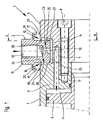
- the device shown in Figures 1 to 4 and designated 1 is used for Supply of pressure medium, for example pressure oil, from a stationary arrangement Component 2 in a two-part rotating component 3, 3 'and one on this by means Screws 8 attached hollow clamping cylinder 4.
- pressure medium for example pressure oil
- the cylinder wall forms the component 3 'is a Piston 5 acted upon by pressure medium, its associated Pressure chamber 6 via channels 7, 7 'provided in the rotating component 3, 3' Supply of the pressure medium is connected to the stationary component 2.
- the stationary component 2 designed as a disk 11 engages with a radial distance into the rotating component 3, 3 ', so that between them an axially directed annular groove 14th and on both sides of the fixed component 2 radial sealing gaps 15 and 16 are formed are.
- the disc 11 with a connection 12 for a not shown Pressure medium supply line and a channel 13, which opens into the annular groove 14, Mistake.
- the channel 7 incorporated in the rotating component 3 is on the Annular groove 14 connected so that the pressure medium supplied via the channel 13, the annular groove 14 and the channels 7 and 7 'in the pressure chamber 6 of Hollow clamping cylinder 4 arrives.
- the End faces 21 and 22 thus each have an inner sealing surface 25 and 26, respectively Pressure chambers 29 and 30 and an outer outer sealing surface 33 and 34 respectively.
- the inner ones Inner sealing surfaces 25 and 26 are dimensioned about twice as large as that Outer sealing surfaces 33 and 34. They are also acted upon in the axial direction Areas of the pressure chambers 29 and 30, which are rectangular in cross section, are larger dimensioned as the inner sealing surfaces 25 and 26. This is a short-term Leveling of the two components allows each other.
- the hollow clamping cylinder 4 via the stationary component 2 and the rotating Component 3 pressure medium supplied, so is in the pressure chamber 6 and the annular groove 14 static pressure built up.
- a subset of the pressure medium is in the in Figure 1 shown position of the two components 2 and 3 to each other on the enlarged radial sealing gap 15 into a web 17 formed on the disk 12 flow out of the formed collecting chamber 19.
- the opposite radial Sealing gap 16 by contact of the outer sealing surface 34 on the disc 12 almost is closed, but the pressure chamber 30 via the control slot 38 with the annular groove 14 is connected, a pressure is built up in this and thus an axially directed Force exerted on the two components 2 and 3.
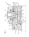
- the end faces 23 and 24 of the stationary component 2 pressure chambers 31 and 32 incorporated, the Control slots 39 and 40 are connected to the annular groove 14.
- the Inner sealing surfaces 27 and 28 and the outer sealing surfaces 35 and 36 are thus on the disk 11 of the stationary component 2, the end faces 21 and 22
- the rotating component 3, 3 ' are designed to be flat.
Description
Die Erfindung bezieht sich auf eine Einrichtung zur Zuführung von Druckmittel aus
einem ortsfesten Bauteil in ein rotierendes Bauteil, gemäss dem Oberbegriff des Anspruchs 1.
(Siche, z.B., DE-4 404 547-A).The invention relates to a device for supplying pressure medium
a stationary component in a rotating component, according to the preamble of
Durch die DE 36 32 677 C2 ist ein umlaufender Hohlspannzylinder, der mit einer derartigen Druckmittelzuführungseinrichtung versehen ist, bekannt. Für jede Druckmittelzuführungsleitung ist hierbei zwischen zwei mit einem Distanzring verspannte Planscheiben ein Dichtring eingesetzt, der mit den Planscheiben die radialen Dichtspalte einschließt. Die einander zugekehrten Flächen der Planscheiben und des Dichtringes sind als ebene Flächen ausgebildet, so daß, sobald Druckveränderungen in einem der radialen Dichtspalte auftreten, der Dichtring in Richtung des anderen Dichtspaltes verschoben und gegen die benachbarte Planscheibe gepreßt wird. Ein hoher Verschleiß durch die dabei auftretenden Reibungskräfte ist in diesem Fall unerläßlich, die Standzeit dieser bekannten nur für gasförmige Druckmedien verwendbaren Druckmittelübertragungeinrichtung ist daher sehr gering. DE 36 32 677 C2 is a revolving hollow clamping cylinder with a such pressure medium supply device is known. For every Pressure medium supply line is between two with a spacer ring tensioned face plates a sealing ring is used, which with the face plates radial sealing gap includes. The facing surfaces of the The face plates and the sealing ring are designed as flat surfaces so that as soon as pressure changes occur in one of the radial sealing gaps, the Sealing ring moved in the direction of the other sealing gap and against the neighboring face plate is pressed. A high level of wear due to this Frictional forces that occur in this case are indispensable, the service life of these known only usable for gaseous pressure media Pressure medium transmission device is therefore very small.
Aufgabe der Erfindung ist es demnach, eine Druckmittelzuführungseinrichtung der eingangs genannten Gattung in der Weise auszubilden, daß eine Anlage der beiden an der Druckmittelübertragung beteiligten Bauteile aneinander unter Druck ausgeschlossen ist, so daß ein Verschleiß durch eine erhöhte Reibung nicht in Kauf genommen werden muß. Vielmehr soll erreicht werden, daß sich die beiden Bauteile zu einander einpendeln und stets eine Mittellage einnehmen, und zwar sowohl bei Stillstand als auch bei Rotation. Der Bauaufwand, mit dem dies zu bewerkstelligen ist, soll gering gehalten werden, dennoch soll über einen langen Zeitraum eine stets zufriedenstellende störungsfreie Betriebsweise gegeben sein.The object of the invention is therefore to provide a pressure medium supply device train the type mentioned in such a way that a system of the two components involved in the pressure medium transmission to one another under pressure is excluded, so that wear due to increased friction is not an option must be taken. Rather, it should be achieved that the two components level off to each other and always take a middle position, both at Standstill as well as rotation. The construction effort with which to accomplish this is to be kept low, but should always be for a long period satisfactory, trouble-free operation.
Gemäß der Erfindung wird dies bei einer Einrichtung zur Zuführung von Druckmittel aus einem ortsfesten Bauteil in ein rotirendes Bauteil der vorgenannten Art dadurch erreicht, daß in die die radial gerichteten Dichtspalte begrenzenden Stimflächen des ortsfesten Bauteils und/oder des rotierenden Bauteils jeweils eine oder mehrere umlaufende Druckkammern eingearbeitet sind, die über einen oder mehrere radial gerichtete Regelschlitze mit der Ringnut zwischen dem ortsfesten Bauteil und dem rotierenden Bauteil verbunden sind, und daß die die radial gerichteten Dichtspalte begrenzenden mit den Druckkammern versehenen Stirnflächen des ortsfesten Bauteils und/oder des rotierenden Bauteils flächengleich zueinander ausgebildet sind.According to the invention, this becomes in a device for supplying pressure medium thereby from a stationary component into a rotating component of the aforementioned type achieved that in the end faces delimiting the radially directed sealing gaps the stationary component and / or the rotating component in each case one or more encircling pressure chambers are incorporated, which are radial over one or more directed control slots with the annular groove between the fixed component and the rotating component are connected, and that the the radially directed sealing gaps limiting end faces of the stationary provided with the pressure chambers Component and / or the rotating component are formed with the same area to each other are.
Die die radial gerichteten Dichtspalte begrenzenden mit den Druckkammern versehenen Stirnflächen des ortsfesten Bauteils oder des rotierenden Bauteils können in bezug auf die Querachse des ortsfesten Bauteils spiegelbildlich flächengleich zueinander ausgebildet sein, es ist aber auch möglich, die dem einen radialen Dichtspalt zugeordneten Druckkammem und Regelschlitze in das ortsfeste Bauteil oder das rotierende Bauteil und die dem anderen radialen Dichtspalt zugeordneten Druckkammem und Regelschlitze in das rotierende Bauteil oder das ortsfeste Bauteil einzuarbeiten.The sealing gaps that delimit the radially directed gaps with the pressure chambers provided end faces of the stationary component or of the rotating component can be mirrored with respect to the transverse axis of the fixed component be of equal area to one another, but it is also possible for one radial sealing gap assigned pressure chambers and control slots in the stationary Component or the rotating component and the other radial sealing gap assigned pressure chambers and control slots in the rotating component or incorporate stationary component.
Zweckmäßig ist es hierbei, die einander zugekehrten Stirnflächen des ortsfesten Bauteils und/oder des rotierenden Bauteils jeweils mit einer flächengleichen Innendichtfläche, einer oder mehreren Druckkammern sowie einer flächengleichen Außendichtfläche zu versehen, wobei die an den Stirnflächen des ortsfesten Bauteils und/oder des rotierenden Bauteils vorgesehenen Innendichtflächen etwa doppelt so groß bemessen sein sollten wie die Außendichtflächen, und die in axialer Richtung beaufschlagten Flächen der Druckkammem größer zu bemessen sind als die Innendichtflächen der radialen Dichtspalte. Außerdem sollten die Druckkammern im Querschnitt rechteckig ausgebildet sein.It is expedient here, the mutually facing end faces of the stationary Component and / or the rotating component each with an equal area Inner sealing surface, one or more pressure chambers as well as an equal area To provide an outer sealing surface, which on the end faces of the stationary component and / or the rotating component provided inner sealing surfaces about twice as much should be dimensioned as large as the outer sealing surfaces, and that in the axial direction acted areas of the pressure chambers are larger than that Inner sealing surfaces of the radial sealing gaps. In addition, the pressure chambers in the Cross section be rectangular.
Bei zwei oder mehreren in das ortsfeste Bauteil und/oder das rotierende Bauteil eingearbeiteten Druckkammern ist es angebracht, diese jeweils über einen oder mehrere Regelschlitze mit der axial gerichteten Ringnut und untereinander zu verbinden.With two or more in the fixed component and / or the rotating component built-in pressure chambers, it is appropriate to use one or several control slots with the axially directed annular groove and with each other connect.
Die den beiden radialen Dichtspalten zugeordneten Regelschlitze sollten jeweils eine gleich groß bemessene Querschnittsfläche aufweisen, auch ist es angezeigt, das ortsfeste Bauteil als ringförmige Scheibe auszubilden und in das rotierende Bauteil eingreifen zu lassen. Des weiteren kann jeder der radial gerichteten Dichtspalte durch eine vorzugsweise durch einen am ortsfesten Bauteil angeformten Steg gebildete Auffangkammern abgedeckt sein.The control slots assigned to the two radial sealing gaps should each have one have the same cross-sectional area, it is also appropriate that to form a stationary component as an annular disk and into the rotating component to intervene. Furthermore, each of the radially directed sealing gaps can by means of a web which is preferably molded onto the stationary component formed collecting chambers to be covered.
Wird eine Einrichtung zur Zuführung von Druckmittel aus einem ortsfesten Bauteil in ein rotierendes Bauteil gemäß der Erfindung ausgebildet, so ist die Gewähr gegeben, daß durch Reibung bedingte Beschädigungen an dem ortsfesten Bauteil und/oder dem rotierenden Bauteil im Bereich der radialen Dichtspalte nahezu ausgeschlossen sind. Die beiden Bauteile pendeln sich vielmehr, und zwar sowohl bei Stillstand als auch bei Rotation sowie bei einer schlagartigen Druckmittelzuführung stets in eine Mittellage ein, ein einseitiges Anpressen wird somit zuverlässig vermieden. Eine lange Lebensdauer ist demnach gewährleistet, zumal sich in den in ihrer Breite sich ständig verändernden radialen Dichtspalten und den im Leckölstrom angeordneten Regelschlitzen keine u. U. im Druckmittel mitgeführten Verunreinigungen ablagern können. Bei sehr einfacher konstruktiver Ausgestaltung ermöglicht die somit wirtschaftlich herzustellende vorschlagsgemäß ausgebildete Einrichtung eine betriebssichere und störungsfreie Übertragung eines auch unter hohem Druck stehenden Druckmittels und hohen Drehzahlen über einen langen Zeitraum.Is a device for supplying pressure medium from a stationary component in formed a rotating component according to the invention, so the guarantee given that damage to the stationary component caused by friction and / or the rotating component in the area of the radial sealing gaps almost excluded are. Rather, the two components oscillate, both with standstill as well as with rotation as well as with a sudden Always pressurize the pressure medium supply in one middle position, one-sided pressing thus reliably avoided. A long lifespan is therefore guaranteed especially since the radial sealing gaps, which are constantly changing in width, and the control slots arranged in the leakage oil flow no u. U. in the pressure medium be able to deposit the contaminants carried along. With a very simple constructive Design enables the economically produced according to the proposal trained facility a reliable and trouble-free transmission of a even under high pressure fluid and high speeds over one long period.
In der Zeichnung ist ein Ausführungsbeispiel einer gemäß der Erfindung ausgebildeten Einrichtung zur Zuführung von Druckmittel aus einem ortsfesten Bauteil in ein rotierendes Bauteil dargestellt, das nachfolgend im einzelnen erläutert ist. Hierbei zeigt:
Figur 1- die an einen Hohlspannzylinder angebaute Druckmittelzuführungseinrichtung, in einem axialen Schnitt,
Figur 2- einen Schnitt nach der Linie II - II der
Figur 1, Figur 3- die Druckmittelzuführungseinrichtung nach
Figur 1 mit an dem ortsfesten Bauteil vorgesehenen Druckkammern, und Figur 4- die Druckmittelzuführungseinrichtung nach
Figur 3 mit jeweils zwei konzentrisch ineinander angeordneten Druckkammern.
- Figure 1
- the pressure medium supply device attached to a hollow clamping cylinder, in an axial section,
- Figure 2
- 2 shows a section along the line II-II of FIG. 1,
- Figure 3
- the pressure medium supply device according to Figure 1 with pressure chambers provided on the stationary component, and
- Figure 4
- the pressure medium supply device according to Figure 3, each with two concentrically arranged pressure chambers.
Die in den Figuren 1 bis 4 dargestellte und mit 1 bezeichnete Einrichtung dient zur
Zuführung von Druckmittel, beispielsweise Drucköl, aus einem ortsfest angeordneten
Bauteil 2 in ein zweiteiliges rotierendes Bauteil 3, 3' sowie einem an diesem mittels
Schrauben 8 befestigten Hohlspannzylinder 4. In den Hohlspannzylinder 4, dessen
Zylinderwand bei dem gezeigten Ausführungsbeispiel das Bauteil 3' bildet, ist ein
von Druckmittel beaufschlagbarer Kolben 5 eingesetzt, dessen zugeordneter
Druckraum 6 über in dem rotierenden Bauteil 3, 3' vorgesehene Kanäle 7, 7' zur
Zuführung des Druckmittels an das ortsfeste Bauteil 2 angeschlossen ist. The device shown in Figures 1 to 4 and designated 1 is used for
Supply of pressure medium, for example pressure oil, from a
Das als Scheibe 11 gestaltete ortsfeste Bauteil 2 greift mit radialem Abstand in das
rotierende Bauteil 3, 3' ein, so daß zwischen diesen eine axial gerichtete Ringnut 14
sowie beiderseits des ortsfesten Bauteils 2 radiale Dichtspalte 15 und 16 gebildet
sind. Außerdem ist die Scheibe 11 mit einem Anschluß 12 für eine nicht gezeigte
Druckmittelzuführungsleitung und einen Kanal 13, der in die Ringnut 14 mündet,
versehen. Und der in dem rotierenden Bauteil 3 eingearbeitete Kanal 7 ist an die
Ringnut 14 angeschlossen, so daß das zugeführte Druckmittel über den Kanal 13,
die Ringnut 14 sowie die Kanäle 7 und 7' in den Druckraum 6 des
Hohlspannzylinders 4 gelangt.The
Die die radialen Dichtspalte 15und 16 begrenzenden Stirnflächen 21 und 22 des
rotierenden Bauteils 3, 3' sind, um eine Anlage an dem ortsfesten Bauteil 2 unter
Druck auszuschließen, in besonderer Weise gestaltet, und zwar sind in die
Stirnflächen 21 und 22 jeweils eine Druckkammer 29 bzw. 30 eingearbeitet, die über
flächengleiche Regelschlitze 37 bzw. 38 mit der Ringnut 14 verbunden sind. Die
Stirnflächen 21 und 22 weisen somit jeweils eine Innendichtfläche 25 bzw. 26, die
Druckkammem 29 bzw. 30 sowie eine äußere Außendichtfläche 33 bzw. 34 auf. In
bezug auf die Querachse der Scheibe 12 sind somit die Stirnflächen 21 und 22
spiegelbildlich flächengleich zueinander ausgebildet, wobei die inneren
Innendichtflächen 25 und 26 etwa doppelt so groß bemessen sind wie die
Außendichtflächen 33 und 34. Auch sind die in axialer Richtung beaufschlagten
Flächen der im Querschnitt rechteckig gestalteten Druckkammem 29 und 30 größer
bemessen als die Innendichtflächen 25 und 26. Dadurch wird ein kurzfristiges
Einpendeln der beiden Bauteile zueinander ermöglicht.The end faces 21 and 22 of the
Wird dem Hohlspannzylinder 4 über das ortsfeste Bauteil 2 und das rotierende
Bauteil 3 Druckmittel zugeführt, so wird in dem Druckraum 6 und der Ringnut 14 ein
statischer Druck aufgebaut. Eine Teilmenge des Druckmittels wird bei der in Figur 1
dargestellten Lage der beiden Bauteile 2 und 3 zueinander über den vergrößerten
radialen Dichtspalt 15 in eine durch einen an der Scheibe 12 angeformten Steg 17
gebildeten Auffangkammer 19 abströmen. Da jedoch der gegenüberliegende radiale
Dichtspalt 16 durch Anlage der Außendichtfläche 34 an der Scheibe 12 nahezu
geschlossen ist, die Druckkammer 30 aber über den Regelschlitz 38 mit der Ringnut
14 verbunden ist, wird in dieser ein Druck aufgebaut und somit eine axial gerichtete
Kraft auf die beiden Bauteile 2 und 3 ausgeübt. In Folge davon wird die
Außendichtfläche 34 von der Scheibe 12 abgehoben, so daß Druckmittel in eine dem
radialen Dichtspalt 16 zugeordnete ebenfalls durch einen angeformten Steg 18
gebildete Auffangkammer 20 gelangt und aus dieser wie auch aus der
Auffangkammer 19 in den Druckmittelkreislauf zurückgeführt wird. Gleichzeitig wird
der radiale Spalt 15 mehr oder weniger geschlossen, die beiden Bauteile 2 und 3
führen demnach bei einer Druckmittelzuführung mittels der Einrichtung 1 ständig
Pendelbewegungen aus, und es stellen sich kurzfristig immer wieder
Gleichgewichtszustände ein. Ein kontrolliertes Abströmen von Druckmittel über die
radialen Dichtspalte 15 und 16 wird dabei in Kauf genommen, eine Anlage unter
Druck der beiden Bauteile 2 und 3 aneinander, durch die an diesen Beschädigungen
hervorgerufen werden können, wird durch das Einpendeln aber zuverlässig
vermieden.The
Bei der Ausführungsvariante nach Figur 3 sind in die Stirnflächen 23 und 24 des
ortsfesten Bauteils 2 Druckkammern 31 und 32 eingearbeitet, die über
Regelschlitze 39 und 40 an die Ringnut 14 angeschlossen sind. Die
Innendichtflächen 27 und 28 sowie die Außendichtflächen 35 und 36 sind somit an
der Scheibe 11 des ortsfesten Bauteils 2 vorgesehen, die Stirnflächen 21 und 22
des rotierenden Bauteils 3, 3' sind dagegen flächenplan gestaltet.In the embodiment variant according to FIG. 3, the end faces 23 and 24 of the
Des weiteren ist es möglich, auch zwei oder mehrere Druckkammern konzentrisch
ineinander in einem der beiden Bauteile 2 oder 3 vorzusehen. Gemäß Figur 4 sind in
die Scheibe 12 des feststehenden Bauteils 2 in die beiden Stirnflächen 23 und 24
jeweils zwei konzentrisch ineinander angeordnete Ringkammern 31 und 31' bzw. 32
und 32' eingearbeitet, die über Regelschlitze 39' bzw. 40' miteinander verbunden
sind. Auch die äußeren Druckkammern 31' und 32' sind somit an die Ringnut 14
angeschlossen, so daß auch in diesen ein Druck aufgebaut werden kann. Und da
bei allen Ausgestaltungen die mit Druckkammern 29, 30 bzw. 31, 32 bzw. 31, 31'
bzw. 32, 32' versehenen Stirnflächen 21, 22 bzw. 23, 24 in bezug auf die Querachse
der Scheibe 11 spiegelbildlich flächengleich zueinander gestaltet sind, ist eine
Verschiebung eines der beiden Bauteile 2 oder 3 in eine Richtung ausgeschlossen,
die Breite der radialen Spalte 15 und 16 wird sich vielmehr stets konstant einstellen.It is also possible to concentrate two or more pressure chambers
to be provided in one of the two
Claims (11)
- A device (1) for supplying fluid under pressure from a stationary component (2) into a rotating component (3, 3'), in particular for supplying fluid under pressure into a hollow clamping cylinder (4) or the like, in which an axially directed annular groove (14) and a radially directed sealing gap (15, 16) are provided between the stationary component (2) and the rotating component (3, 3') and in which one or more circumferential pressure chambers (29, 30 or 31, 32 or 31, 31', 32, 32') each are worked into the end surfaces (21, 22 or 23, 24) of the stationary component (2) and/or of the rotating component (3, 3') which limit the radially directed sealing gap (15, 16),
characterised in that,
the pressure chambers (29, 30 or 31, 32 or 31, 31', 32, 32') are connected to the annular groove (14) between the stationary component (2) and the rotating component (3, 3') by means of one or more radially directed control slots (37, 38 or 39, 40 or 39, 39', 40, 40'), and that the end surfaces (21, 22 or 23, 24) of the stationary component (2) and/or of the rotating component (3, 3') which limit the radially directed sealing gap (15, 16) and are provided with the pressure chambers (29, 30 or 31, 32 or 31, 31', 32, 32') are formed with equal surface areas. - The device in accordance with Claim 1,
characterised in that,
the end surfaces (21, 22 or 23, 24) of the stationary component (2) or of the rotating component (3) which limit the radially directed sealing gap (15, 16) and are provided with the pressure chambers (29, 30 or 31, 32 or 31, 31', 32, 32') are formed with equal surface areas in a mirror image of one another. - The device in accordance with Claim 2,
characterised in that,
the pressure chambers (29) and control slots (37) which are assigned to the one radial sealing gap (15) are worked into the stationary component (2) or the rotating component (3) and the pressure chambers (32) and control slots- (40) which are assigned to the other radial sealing gap (16) are worked into the rotating component (3) or the stationary component (2). - The device in accordance with one of Claims 1 to 3,
characterised in that,
the end surfaces (21, 22 or 23, 24) of the stationary component (2) and/or of the rotating component (3, 3') which face one another are each provided with an internal sealing surface (25, 26 or 27, 28) having the same surface area, with one or more pressure chambers (29, 30 or 31, 32 or 31, 31', 32, 32') and with an external sealing surface (33, 34 or 35, 36) having the same surface area. - The device in accordance with Claim 4,
characterised in that,
the internal sealing surfaces (25, 26 or 27, 28) provided on the end surfaces (21, 22 or 23, 24) of the stationary component (2) and/or of the rotating component (3, 3') are approximately twice as large as the external sealing surfaces (33, 34 or 35, 36). - The device in accordance with Claim 4 or 5,
characterised in that,
the surfaces of the pressure chambers (29, 30 or 31, 32) which are subject to pressure in an axial direction are larger than the internal sealing surfaces (25, 26 or 27, 28) of the radial sealing gap (15, 16). - The device in accordance with one of Claims 4 to 6,
characterised in that,
- the pressure chambers (29, 30 or 31, 32) have a rectangular cross-section. - The device in accordance with one of Claims 4 to 7,
characterised in that,
when two or more pressure chambers (31, 31' or 32, 32') are worked into the stationary component (2) and/or the rotating component (3, 3'), each of them are connected to the axially directed annular groove (14) via one or more control slots (39, 39' or 40, 40') and are interconnected. - The device in accordance with one of Claims 4 to 8,
characterised in that,
the control slots (37, 38 or 39, 40) assigned to the two radial sealing gaps (15, 16) each have the same sized cross-sectional area. - The device in accordance with one of Claims 1 to 9,
characterised in that,
the stationary component (2) is formed as an annular disc (11) and engages in the rotating component (3). - The device in accordance with one of Claims 1 to 10,
characterised in that,
each of the radially directed sealing gaps (15, 16) is covered by a collecting chamber (19, 20), which in a preferred embodiment is formed by a web (17, 18) formed onto the stationary component (2).
Applications Claiming Priority (2)
| Application Number | Priority Date | Filing Date | Title |
|---|---|---|---|
| DE19817331 | 1998-04-18 | ||
| DE19817331A DE19817331A1 (en) | 1998-04-18 | 1998-04-18 | Pressure medium supply device |
Publications (3)
| Publication Number | Publication Date |
|---|---|
| EP0950464A2 EP0950464A2 (en) | 1999-10-20 |
| EP0950464A3 EP0950464A3 (en) | 2002-05-02 |
| EP0950464B1 true EP0950464B1 (en) | 2003-09-03 |
Family
ID=7865024
Family Applications (1)
| Application Number | Title | Priority Date | Filing Date |
|---|---|---|---|
| EP99105900A Expired - Lifetime EP0950464B1 (en) | 1998-04-18 | 1999-03-24 | Device for supplying fluid under pressure |
Country Status (4)
| Country | Link |
|---|---|
| US (1) | US6145890A (en) |
| EP (1) | EP0950464B1 (en) |
| JP (1) | JP2000028063A (en) |
| DE (2) | DE19817331A1 (en) |
Families Citing this family (3)
| Publication number | Priority date | Publication date | Assignee | Title |
|---|---|---|---|---|
| US7083200B2 (en) * | 2003-08-28 | 2006-08-01 | Focal Technologies Corporation | Fluid rotary union |
| NO323924B1 (en) * | 2004-08-31 | 2007-07-23 | Atle Kvamme | Device for pressure compensated swivel |
| JP6056657B2 (en) * | 2012-06-22 | 2017-01-11 | 株式会社デンソー | Piping connection device and heat pump cycle device having the same |
Family Cites Families (12)
| Publication number | Priority date | Publication date | Assignee | Title |
|---|---|---|---|---|
| US3392995A (en) * | 1966-08-23 | 1968-07-16 | Malan Vibrator Co Inc | Pressure balanced ball joint |
| CH584371A5 (en) * | 1974-12-03 | 1977-01-31 | Cyphelly Ivan J | |
| US4139220A (en) * | 1977-02-07 | 1979-02-13 | Fmc Corporation | Swivel joint sealing system |
| DE3004807C2 (en) * | 1980-02-09 | 1984-11-15 | SMW Schneider & Weißhaupt GmbH, 7996 Meckenbeuren | Pressure medium supply device for rotating clamping cylinders on machine tools |
| JPS5840578A (en) * | 1981-09-04 | 1983-03-09 | Ricoh Co Ltd | Attaching and detaching device for cleaning device |
| US4561679A (en) * | 1982-07-26 | 1985-12-31 | Exxon Production Research Co. | Seal pressure reduction system |
| DE3632677A1 (en) * | 1986-09-26 | 1988-04-07 | Berg & Co Gmbh | Revolving hollow clamping cylinder |
| US4828292A (en) * | 1987-12-31 | 1989-05-09 | Amtel, Inc. | Adjustable fluid swivel |
| US4925219A (en) * | 1988-07-21 | 1990-05-15 | Jack Pollack | Fluid swivel assembly |
| DE4124153A1 (en) * | 1991-07-20 | 1993-01-21 | Smw Spanneinrichtungen | DEVICE FOR TRANSMITTING A MEDIUM |
| DE4404547C2 (en) * | 1994-02-12 | 1997-08-28 | Thomas Hiestand | Pressure medium supply |
| US5720503A (en) * | 1995-11-08 | 1998-02-24 | Single Buoy Moorings Inc. | Sealing sytem--anti collapse device |
-
1998
- 1998-04-18 DE DE19817331A patent/DE19817331A1/en not_active Ceased
-
1999
- 1999-03-24 DE DE59906820T patent/DE59906820D1/en not_active Expired - Lifetime
- 1999-03-24 EP EP99105900A patent/EP0950464B1/en not_active Expired - Lifetime
- 1999-04-14 US US09/291,397 patent/US6145890A/en not_active Expired - Fee Related
- 1999-04-16 JP JP11109746A patent/JP2000028063A/en active Pending
Also Published As
| Publication number | Publication date |
|---|---|
| DE59906820D1 (en) | 2003-10-09 |
| DE19817331A1 (en) | 1999-10-21 |
| JP2000028063A (en) | 2000-01-25 |
| US6145890A (en) | 2000-11-14 |
| EP0950464A2 (en) | 1999-10-20 |
| EP0950464A3 (en) | 2002-05-02 |
Similar Documents
| Publication | Publication Date | Title |
|---|---|---|
| DE3914961C2 (en) | SHAFT SEAL WITH CYLINDRICAL SEALING SURFACE | |
| EP0242741B1 (en) | Seatassembly | |
| DE2855453A1 (en) | SEAL ARRANGEMENT BETWEEN AN INNER PART, IN PARTICULAR A SHAFT, AND AN EXTERNAL PART SURROUNDING THIS | |
| DE3602051A1 (en) | ROLLER BEARING TURN JOINT | |
| DE2529403A1 (en) | SEALING ARRANGEMENT FOR SEALING BETWEEN TWO LEVEL SURFACES | |
| EP0525371B1 (en) | Transfer arrangement for a medium | |
| DE4341167A1 (en) | Device for transferring a print medium | |
| EP0950464B1 (en) | Device for supplying fluid under pressure | |
| WO1991019120A1 (en) | Seal assembly | |
| DE3342131C2 (en) | ||
| DE1812635C3 (en) | Radial piston pump | |
| EP0708267A2 (en) | Gas spring | |
| DE2402237A1 (en) | HYDROSTATIC BEARING | |
| DE4232191C1 (en) | Device to adjust eccentricity of eccentric radial bearing - has hydraulic double-piston driving unit and releaseable locking device to move eccentric ring | |
| EP0974782B1 (en) | Device for supplying fluid under pressure | |
| DE2905631C2 (en) | Roll stand with at least one support roll surrounded by a loosely rotatable sleeve | |
| DE4133262A1 (en) | Pressure medium feed from rotary distributor to shaft - has ring chamber with facing radial side surfaces, formed as sealing faces, and with sealing rings | |
| DE3204647C2 (en) | Device for feeding a pressure medium from a stationary housing to a rotatable shaft | |
| DE2409721A1 (en) | HYDRODYNAMIC LIFTING OF TURNING CUTTERS AND TOOLS ON TURNING SPINDLES FOR THE PURPOSE OF THE TURNING SURFACE FREE RETURN WHEN THE TURNING SPINDLE RUNS | |
| DE2047311A1 (en) | Spindle head | |
| DE2215450C3 (en) | Free jet servo valve | |
| DE10028336C1 (en) | Engine with axial piston has through guide channel between at least one tooth crown surface and tooth space bottom opposite it | |
| DE3811952A1 (en) | DEVICE FOR HYDROSTATICALLY SUPPORTING ROLLS OF A ROLLING MILL | |
| DE2821339B2 (en) | Hydraulic piston-cylinder device for generating axial piston oscillation | |
| EP0144786A1 (en) | Separation device |
Legal Events
| Date | Code | Title | Description |
|---|---|---|---|
| PUAI | Public reference made under article 153(3) epc to a published international application that has entered the european phase |
Free format text: ORIGINAL CODE: 0009012 |
|
| AK | Designated contracting states |
Kind code of ref document: A2 Designated state(s): AT BE CH CY DE DK ES FI FR GB GR IE IT LI LU MC NL PT SE Kind code of ref document: A2 Designated state(s): AT BE CH CY DE LI |
|
| AX | Request for extension of the european patent |
Free format text: AL;LT;LV;MK;RO;SI |
|
| PUAL | Search report despatched |
Free format text: ORIGINAL CODE: 0009013 |
|
| AK | Designated contracting states |
Kind code of ref document: A3 Designated state(s): AT BE CH CY DE DK ES FI FR GB GR IE IT LI LU MC NL PT SE |
|
| AX | Request for extension of the european patent |
Free format text: AL;LT;LV;MK;RO;SI |
|
| 17P | Request for examination filed |
Effective date: 20021016 |
|
| GRAH | Despatch of communication of intention to grant a patent |
Free format text: ORIGINAL CODE: EPIDOS IGRA |
|
| AKX | Designation fees paid |
Free format text: AT BE CH CY DE LI |
|
| RBV | Designated contracting states (corrected) |
Designated state(s): CH DE FR GB IT LI |
|
| GRAH | Despatch of communication of intention to grant a patent |
Free format text: ORIGINAL CODE: EPIDOS IGRA |
|
| GRAA | (expected) grant |
Free format text: ORIGINAL CODE: 0009210 |
|
| AK | Designated contracting states |
Kind code of ref document: B1 Designated state(s): CH DE FR GB IT LI |
|
| PG25 | Lapsed in a contracting state [announced via postgrant information from national office to epo] |
Ref country code: GB Free format text: LAPSE BECAUSE OF FAILURE TO SUBMIT A TRANSLATION OF THE DESCRIPTION OR TO PAY THE FEE WITHIN THE PRESCRIBED TIME-LIMIT Effective date: 20030903 |
|
| REG | Reference to a national code |
Ref country code: GB Ref legal event code: FG4D Free format text: NOT ENGLISH |
|
| REG | Reference to a national code |
Ref country code: CH Ref legal event code: EP |
|
| REF | Corresponds to: |
Ref document number: 59906820 Country of ref document: DE Date of ref document: 20031009 Kind code of ref document: P |
|
| REG | Reference to a national code |
Ref country code: IE Ref legal event code: FG4D Free format text: GERMAN |
|
| GBV | Gb: ep patent (uk) treated as always having been void in accordance with gb section 77(7)/1977 [no translation filed] |
Effective date: 20030903 |
|
| PG25 | Lapsed in a contracting state [announced via postgrant information from national office to epo] |
Ref country code: LI Free format text: LAPSE BECAUSE OF NON-PAYMENT OF DUE FEES Effective date: 20040331 Ref country code: CH Free format text: LAPSE BECAUSE OF NON-PAYMENT OF DUE FEES Effective date: 20040331 |
|
| REG | Reference to a national code |
Ref country code: IE Ref legal event code: FD4D |
|
| ET | Fr: translation filed | ||
| PLBE | No opposition filed within time limit |
Free format text: ORIGINAL CODE: 0009261 |
|
| STAA | Information on the status of an ep patent application or granted ep patent |
Free format text: STATUS: NO OPPOSITION FILED WITHIN TIME LIMIT |
|
| 26N | No opposition filed |
Effective date: 20040604 |
|
| REG | Reference to a national code |
Ref country code: CH Ref legal event code: PL |
|
| PGFP | Annual fee paid to national office [announced via postgrant information from national office to epo] |
Ref country code: FR Payment date: 20090318 Year of fee payment: 11 |
|
| REG | Reference to a national code |
Ref country code: FR Ref legal event code: ST Effective date: 20101130 |
|
| PG25 | Lapsed in a contracting state [announced via postgrant information from national office to epo] |
Ref country code: FR Free format text: LAPSE BECAUSE OF NON-PAYMENT OF DUE FEES Effective date: 20100331 |
|
| PGFP | Annual fee paid to national office [announced via postgrant information from national office to epo] |
Ref country code: IT Payment date: 20120327 Year of fee payment: 14 |
|
| PGFP | Annual fee paid to national office [announced via postgrant information from national office to epo] |
Ref country code: DE Payment date: 20120427 Year of fee payment: 14 |
|
| REG | Reference to a national code |
Ref country code: DE Ref legal event code: R119 Ref document number: 59906820 Country of ref document: DE Effective date: 20131001 |
|
| PG25 | Lapsed in a contracting state [announced via postgrant information from national office to epo] |
Ref country code: DE Free format text: LAPSE BECAUSE OF NON-PAYMENT OF DUE FEES Effective date: 20131001 |
|
| PG25 | Lapsed in a contracting state [announced via postgrant information from national office to epo] |
Ref country code: IT Free format text: LAPSE BECAUSE OF NON-PAYMENT OF DUE FEES Effective date: 20130324 |