EP0949749A1 - Improved winding for linear motors without slots - Google Patents
Improved winding for linear motors without slots Download PDFInfo
- Publication number
- EP0949749A1 EP0949749A1 EP98122360A EP98122360A EP0949749A1 EP 0949749 A1 EP0949749 A1 EP 0949749A1 EP 98122360 A EP98122360 A EP 98122360A EP 98122360 A EP98122360 A EP 98122360A EP 0949749 A1 EP0949749 A1 EP 0949749A1
- Authority
- EP
- European Patent Office
- Prior art keywords
- winding
- motor
- linear
- air gap
- length
- Prior art date
- Legal status (The legal status is an assumption and is not a legal conclusion. Google has not performed a legal analysis and makes no representation as to the accuracy of the status listed.)
- Granted
Links
Images


Classifications
-
- H—ELECTRICITY
- H02—GENERATION; CONVERSION OR DISTRIBUTION OF ELECTRIC POWER
- H02K—DYNAMO-ELECTRIC MACHINES
- H02K41/00—Propulsion systems in which a rigid body is moved along a path due to dynamo-electric interaction between the body and a magnetic field travelling along the path
- H02K41/02—Linear motors; Sectional motors
- H02K41/03—Synchronous motors; Motors moving step by step; Reluctance motors
- H02K41/031—Synchronous motors; Motors moving step by step; Reluctance motors of the permanent magnet type
-
- H—ELECTRICITY
- H02—GENERATION; CONVERSION OR DISTRIBUTION OF ELECTRIC POWER
- H02K—DYNAMO-ELECTRIC MACHINES
- H02K3/00—Details of windings
- H02K3/04—Windings characterised by the conductor shape, form or construction, e.g. with bar conductors
- H02K3/26—Windings characterised by the conductor shape, form or construction, e.g. with bar conductors consisting of printed conductors
Definitions
- This invention relates to linear motors of the type including two parallel ferromagnetic plates with a coil positioned between them.
- the coil When the coil is energized, a linear movement is produced by the interaction of the energized coil and the magnetic flux from the ferromagnetic plates.
- the coil may be a single phase or polyphase winding and the ferromagnetic plates may generate the magnetic field by permanent magnets or by electromagnetic induction.
- the winding according to the linear motor of this invention contains no permeable material. As such, it is 'slotless' or 'ironless' and has the advantage of very light weight and zero cogging.
- motors of this general type are known including motors disclosed in US-A-4,151,921 describing the general construction and advantages of such linear motors, in US-A-4,749,921 describing an improved construction method and the addition of cooling, and in US-Re-34,674 describing an alternate construction with overlapping coils.
- the coil is typically molded in epoxy and/or retained by a non-magnetic plate (see US-A-4,749,921) which provides a convenient means of positioning and mechanically retaining the coil between the ferromagnetic plates.
- the slotless linear motor of the invention having a distributed winding and comprising a plurality of permanent magnets providing alternating magnetic pole faces disposed along a linear air gap of predetermined height; a distributed linear winding of predetermined outside dimensions located at least in part in said air gap and including a plurality of layered conductor patterns and insulation between adjacent ones of said conductor patterns; said linear winding and said alternating magnetic pole faces being mounted for relative linear movement; said layered conductor patterns including conductor portions of predetermined length perpendicular to the direction of said linear movement; the length of said perpendicular conductor portion, the height of said linear air gap and the outside dimension of said winding being selected to desired performance characteristics; magnetic material providing a flux return path for said permanent magnets and across said linear air gap; and means for energizing said winding according to the position of said winding relative to said permanent magnets.
- the linear motor of this invention utilizes a flat, ironless coil winding which can be of the printed circuit type.
- a winding can be stamped, etched or deposited and adhered to a rigid structure.
- the winding provides coils that are relatively movable between straight, parallel rows of stationary magnets.
- the winding can also be fabricated using insulated wire to form a distributed winding.
- the winding can consist of multi-turn coils which overlap one another.
- the armature conductor pattern is generally continuous over the length of the winding.
- the winding can be either a lap or wave configuration with one half of each coil on one side of a substrate and the next half of each coil being on the other side of the substrate.
- the coils can have a large variety of configurations. As long as each coil is the same, there is very little wasted space in the air gap.
- the conductor patterns for distributed wire or multi-turn windings can be mounted on one side of a support.
- the general linear motor structure is illustrated in Fig. 1 and Figs. 2A-2D.
- the linear motor includes a moving coil (or "slider") 10 being a stamped, deposited or etched winding on an insulated substrate.
- the slider 10 is accommodated in the air gap 17 between parallel arrays of permanent magnet field members 12.
- the permanent magnet field members 12 are mounted on back iron members 20 which provide a flux return path for the magnets. There is no limit to the length of the winding or the length of the permanent magnet field arrays.
- Winding 10 is a 'printed circuit' type structure which can be either a stamped, deposited or etched conductor pattern that is interconnected to create a complete winding with any desired number of effective coils. Winding 10 is mounted in the slider carriage which can be moved by sliding along rods 16 which are secured to the stationary magnet 12 and back iron structure 20 at the ends.
- the coil conductors typically have a rectangular cross section and are bonded to a thin, high strength, insulating layer substrate 26, preferably by a resin epoxy.
- the substrate can be any electrical insulation material, but typically consists of materials such as Fiberglass, Mylar®, Kapton® or Nomex® insulation.
- the resulting construction is extremely rigid with a high mechanical stiffness in both the direction of travel and parallel to the magnetic flux path. As such, the winding is self-supporting without the need for any further mechanical support.
- the armature can, therefore, be made much thinner than in the case of a conventional wire winding.
- the winding can be encapsulated in an epoxy-type or plastic material for better thermal properties, but such encapsulation is optional and is not needed for mechanical support.
- the manufacturing cost is very low.
- the stamped pattern is adhesively adhered to the insulating substrate, and then the bridging connections between conductors on opposite sides of the substrate are made by welding.
- the conductor patterns may be created by depositing the copper pattern on a substrate such as a PC board or by etching the pattern into a copper-clad board.
- the etched or deposited conductor patterns on opposite sides of the substrate can be interconnected by through hole plating.
- the air gap flux, and therefore the motor force constant K f are a direct function of the air gap between the poles of the facing magnets.
- a thinner winding structure is generally desirable to increase the motor force constant and to reduce the slider weight.
- An increase in the motor force constant K f and the reduced weight of the slider enhance performance and increase the possible acceleration.
- a moving cable 18 (Figs. 1 and 2A-2D) on the slider 14 can be used to bring power to the armature winding coils in the correct sequence.
- the number of coils in the armature winding depends on the application and the amount of force and travel needed.
- a single phase coil is sufficient to create linear movement. However, for continuous movement over longer distances several coils are preferably connected in a number of phases.
- the phases of the winding are electronically commutated.
- a sensor 19 (Fig. 2B) is typically attached to or embedded in the moving armature to sense the position of the winding relative to the stationary magnets.
- the sensor(s) may be optical, magnetic, capacitive or inductive.
- a typical application employs Hall effect sensors to sense the magnet location. Another possible arrangement is to use the armature-generated back emf to indicate position. Using the correct ratio of magnet pitch to coil pitch, the back emf can be modified to the desired wave shape which, in most cases, is sinusoidal. Electronic commutation is well known in the art and is employed in many rotary and linear motors to eliminate the need for mechanical brushes.
- a transistor array (not shown) is built into slider 14 and energizes the winding coils in the correct sequence as indicated by sensor 19.
- the armature winding conductor pattern can be a wave winding configuration where a conductor 30 of a coil 31 spans approximately the distance between adjacent pole face centers as shown in Fig. 3A.
- the conductor pattern can also be of a lap confiuration as shown in Figs. 3B and 3C.
- the spatial relationship of the armature winding coils to the permanent magnets is shown in Fig. 3C.
- the coil span is approximately equal to the distance between adjacent magnet pole centers.
- Other arrangements are possible to, for example, adjust the shape of the motor back emf.
- Each coil consists of a pair of conductors located on opposite sides of insulating substrate 26.
- the conductor ends can be welded to form bridging connections.
- the connections between conductors on opposite sides of the insulating substrate can be made by through hole plating interconnections.
- Figs. 4A-4C By adjusting the conductor pattern in the wave or in the lap configuration, the important performance characteristics in the motor can be selectively optimized as shown in Figs. 4A-4C.
- Fig. 4A which is the wave configuration
- the ratio of the straight portion of the conductor L M perpendicular to the direction of movement to the overall height of the air gap L S can be adjusted as desired. Adjusting this ratio affects four key motor parameters, namely the motor back emf K e , the motor force constant K f , the winding resistance R, and the motor force ripple F r .
- Selected performance characteristics can be optimized by adjusting the L M to L S ratio.
- One of the advantages of the invention is that this ratio can be easily adjusted as required. For example, reducing the L M to L S ratio to 0 (Fig. 4C) creates a helical type winding and produces the lowest winding resistance. This can be advantageous in designs where it is important to reduce motor Joule losses.
- the motor force constant K f can be optimized by using a high L M to L S ratio (approaching 1.0, as shown in Fig. 4A) such that the conductor straight portion is long and orthogonal to the direction of motion.
- adjusting the L M to L S ratio has an important effect on the motor back emf wave shape, and thereby, the motor force ripple F r .
- the motor back emf wave shape tends to be more trapezoidal. This wave shape is also affected by the magnet width and the winding pitch. As the L M to L S ratio approaches 0, the back emf wave shape becomes more sinusoidal. Adjusting this back emf wave shape according to the intended drive electronics is a significant factor in reducing the motor force ripple. The flexibility of the proposed design allows for the practical elimination of motor force ripple.
- the proper constant for making this determination is the motor constant Km (Newtons/Watt 1/2 ). Optimizing the motor constand Km allows for a maximum developed force for each watt of dissipated heat.
- phase currents applied to each phase are sinusoidal, with three-phase operation the total developed force is consistent (no variations in developed force) only if the motor back emf is also sinusoidal. Where minimum force ripple is important, the motor back emf and the resultant force ripple should also be considered.
- the motor constant Km and the motor force ripple F r when driven by a sinusoidal current can be optimized and performance increased. This is particularly true in polyphase linear motors of this type which use individual coils, whether overlapping or non-overlapping, to create the coil assembly.
- a continuous winding that is distributed over the entire length of the active assembly has a distinct advantage over individual coils where multiple turns are wound in place.
- Such multi-turn coils have a poor spatial distribution with unusable space particularly at the coil centers.
- the spatial distribution can be improved by using overlapping coils, but this arrangement requires long end turns which also produce undesirable resistance to each phase.
- the winding configuration that avoids these problems while optimizing Km for the same active volume is a distributed winding as shown in Fig. 3B.
- a distributed winding as shown in Fig. 3B.
- Such a continuous distributed winding can be made either with conventional round or square wire or by using stamped, cut or etched conductor techniques.
- the coil is a continuous distributed winding, it avoids having multiple conductors in one area, as with individual coils, and the problem of overlapping coils is eliminated. This makes it possible to consider alternate winding patterns that might serve to increase Km or further improve force ripple.
- Figs. 4A to 4C show one coil turn of a distributed winding where the length of the main straight portion L M of the conductor is adjusted as a ratio of the active height of the magnet L B .
- L S is the total height of the conductor pattern.
- Figs. 5A to 5C show multiple turns of this distributed winding in a lap configuration.
- the motor back emf (K e ) When the winding pattern is adjusted by changing the main straight portion L M or by changing the total height L S , three parameters are affected: the motor back emf (K e ), the winding electrical resistance (R), and the developed force ripple (F r ).
- the motor force constant (K f ) and the winding electrical resistance ® are combined into one meaningful parameter Km, referred to as the motor constant.
- Tables 1 to 4 show the results when L M and L S are adjusted for a given magnet height L B :
- the data show that the optimum winding pattern for minimizing force ripple is not the same for optimizing the motor constant Km. Therefore, depending on the application, some compromise between these two patterns is required.
- the torque ripple data are tabulated in Fig. 6.
- the length of the straight portion should be zero or close to zero.
- the conventional teaching of the prior art does not apply.
- the coil active length should be substantially straight and perpendicular to the direction of travel and, therefore, the magnetic flux emanating from the ferromagnetic plates does not produce an optimal linear motor.
- the force constant is maximized, as intuitive teaching would suggest when the coil active length L M is substantially straight and at its longest length, optimum Km and force ripple occur at other configurations.
- the data show that optimal Km occurs when L M is equal to L B which essentially means that the end turns in the inactive area have been reduced to zero.
- the maximum motor constant Km occurs at about 70% straight portion length. High motor constant values are achieved when the straight portion is greater than 50% and preferably in the range of 50% to 85%.
- the foregoing disclosure describes a preferred embodiment of the invention. It will be obvious to those skilled in the art that the present invention is applicable to ironless motors with distributed windings, whether wire wound, stamped, cut or etched. The invention is likewise applicable to windings with multi-turn coils which overlap one another.
- the motor according to the invention provides increased flexibility to adjust winding patterns for optimum advantage in an ironless linear motor such that optimum patterns can be established for maximum motor constant and minimum force ripple.
Abstract
Description
- This invention relates to linear motors of the type including two parallel ferromagnetic plates with a coil positioned between them. When the coil is energized, a linear movement is produced by the interaction of the energized coil and the magnetic flux from the ferromagnetic plates. The coil may be a single phase or polyphase winding and the ferromagnetic plates may generate the magnetic field by permanent magnets or by electromagnetic induction.
- The winding according to the linear motor of this invention contains no permeable material. As such, it is 'slotless' or 'ironless' and has the advantage of very light weight and zero cogging. Several motors of this general type are known including motors disclosed in US-A-4,151,921 describing the general construction and advantages of such linear motors, in US-A-4,749,921 describing an improved construction method and the addition of cooling, and in US-Re-34,674 describing an alternate construction with overlapping coils.
- In motors of this type, the coil is typically molded in epoxy and/or retained by a non-magnetic plate (see US-A-4,749,921) which provides a convenient means of positioning and mechanically retaining the coil between the ferromagnetic plates.
- Although this type of ironless linear motor has been in existence for some time, very little has been done to optimize the coil pattern in order to improve performance. Having no slots to constrain the coil, complete freedom exists to adjust the coil windings to almost any pattern that is of advantage for performance or manufacturing benefits.
- It is significant to note that, for example, US-Re-34,674 teaches that the coil is substantially perpendicular to the longitudinal axis of the ferromagnetic plate (perpendicular to the direction of motion) and US-A-4,749,921 teaches that the coil contains substantially straight runs. While it is conventional to consider that straight coils perpendicular to the longitudinal axis produce the maximum force, it is not always advantageous to use such a construction, particularly in a linear motor where motor heating is of concern.
- It is an object of this invention to provide alternate coil patterns that produce higher performance and present advantages over prior commonly used patterns.
- This is achieved by the slotless linear motor of the invention having a distributed winding and comprising a plurality of permanent magnets providing alternating magnetic pole faces disposed along a linear air gap of predetermined height; a distributed linear winding of predetermined outside dimensions located at least in part in said air gap and including a plurality of layered conductor patterns and insulation between adjacent ones of said conductor patterns; said linear winding and said alternating magnetic pole faces being mounted for relative linear movement; said layered conductor patterns including conductor portions of predetermined length perpendicular to the direction of said linear movement; the length of said perpendicular conductor portion, the height of said linear air gap and the outside dimension of said winding being selected to desired performance characteristics; magnetic material providing a flux return path for said permanent magnets and across said linear air gap; and means for energizing said winding according to the position of said winding relative to said permanent magnets.
- The linear motor of this invention utilizes a flat, ironless coil winding which can be of the printed circuit type. Such a winding can be stamped, etched or deposited and adhered to a rigid structure. The winding provides coils that are relatively movable between straight, parallel rows of stationary magnets. The winding can also be fabricated using insulated wire to form a distributed winding. Furthermore, the winding can consist of multi-turn coils which overlap one another.
- The armature conductor pattern is generally continuous over the length of the winding. The winding can be either a lap or wave configuration with one half of each coil on one side of a substrate and the next half of each coil being on the other side of the substrate. The coils can have a large variety of configurations. As long as each coil is the same, there is very little wasted space in the air gap. The conductor patterns for distributed wire or multi-turn windings can be mounted on one side of a support.
- In designing the winding according to the invention, particular attention is paid to the length of the straight portion perpendicular to the direction of linear motion (LM) compared to the height of the linear air gap (LB) and the outside dimension of the winding (LS). Selection of these dimensions determines four key motor parameters, namely the motor back emf Ke, the motor force constant Kf, the winding resistance R, and the motor force ripple Fr.
- The foregoing and other objects of the invention are achieved as described in the following detailed specification which includes the drawings, wherein
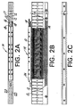
- Fig. 1 is a perspective view of a linear motor structure according to a preferred embodiment;
- Figs. 2A-2D are top, bottom, plan and end views of the linear motor shown in Fig. 1;
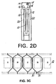
- Figs. 3A and 3B illustrate a distributed wave and lap winding configuration, respectively;
- Fig. 3C illustrates the relationship of the armature coils to the permanent magnets;
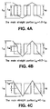
- Figs. 4A-4C illustrate distributed windings according to the invention with straight portions perpendicular to the direction of movement being of different lengths;
- Figs. 5A-5C show multiple turns of distributed windings with different straight portion lengths;
- Fig. 6 is a data tabulation of torque ripple versus the length of the conductor straight portion; and
- Fig. 7 is a data tabulation of the motor constant versus the length of the conductor straight portion.
-
- The general linear motor structure according to a preferred embodiment of the invention is illustrated in Fig. 1 and Figs. 2A-2D. The linear motor includes a moving coil (or "slider") 10 being a stamped, deposited or etched winding on an insulated substrate. The
slider 10 is accommodated in the air gap 17 between parallel arrays of permanentmagnet field members 12. The permanentmagnet field members 12 are mounted onback iron members 20 which provide a flux return path for the magnets. There is no limit to the length of the winding or the length of the permanent magnet field arrays. -
Winding 10 is a 'printed circuit' type structure which can be either a stamped, deposited or etched conductor pattern that is interconnected to create a complete winding with any desired number of effective coils.Winding 10 is mounted in the slider carriage which can be moved by sliding alongrods 16 which are secured to thestationary magnet 12 andback iron structure 20 at the ends. - As shown in Figs. 2A-2D, the coil conductors typically have a rectangular cross section and are bonded to a thin, high strength,
insulating layer substrate 26, preferably by a resin epoxy. The substrate can be any electrical insulation material, but typically consists of materials such as Fiberglass, Mylar®, Kapton® or Nomex® insulation. The resulting construction is extremely rigid with a high mechanical stiffness in both the direction of travel and parallel to the magnetic flux path. As such, the winding is self-supporting without the need for any further mechanical support. The armature can, therefore, be made much thinner than in the case of a conventional wire winding. The winding can be encapsulated in an epoxy-type or plastic material for better thermal properties, but such encapsulation is optional and is not needed for mechanical support. When the windings are mechanically stamped from a copper sheet, the manufacturing cost is very low. The stamped pattern is adhesively adhered to the insulating substrate, and then the bridging connections between conductors on opposite sides of the substrate are made by welding. In an alternate construction, the conductor patterns may be created by depositing the copper pattern on a substrate such as a PC board or by etching the pattern into a copper-clad board. The etched or deposited conductor patterns on opposite sides of the substrate can be interconnected by through hole plating. - The air gap flux, and therefore the motor force constant Kf, are a direct function of the air gap between the poles of the facing magnets. A thinner winding structure is generally desirable to increase the motor force constant and to reduce the slider weight. An increase in the motor force constant Kf and the reduced weight of the slider enhance performance and increase the possible acceleration.
- Several techniques can be used to provide commutation of armature winding 10 in the moving slider. A moving cable 18 (Figs. 1 and 2A-2D) on the
slider 14 can be used to bring power to the armature winding coils in the correct sequence. The number of coils in the armature winding depends on the application and the amount of force and travel needed. A single phase coil is sufficient to create linear movement. However, for continuous movement over longer distances several coils are preferably connected in a number of phases. The phases of the winding are electronically commutated. A sensor 19 (Fig. 2B) is typically attached to or embedded in the moving armature to sense the position of the winding relative to the stationary magnets. The sensor(s) may be optical, magnetic, capacitive or inductive. A typical application employs Hall effect sensors to sense the magnet location. Another possible arrangement is to use the armature-generated back emf to indicate position. Using the correct ratio of magnet pitch to coil pitch, the back emf can be modified to the desired wave shape which, in most cases, is sinusoidal. Electronic commutation is well known in the art and is employed in many rotary and linear motors to eliminate the need for mechanical brushes. A transistor array (not shown) is built intoslider 14 and energizes the winding coils in the correct sequence as indicated bysensor 19. - The armature winding conductor pattern can be a wave winding configuration where a
conductor 30 of acoil 31 spans approximately the distance between adjacent pole face centers as shown in Fig. 3A. The conductor pattern can also be of a lap confiuration as shown in Figs. 3B and 3C. The spatial relationship of the armature winding coils to the permanent magnets is shown in Fig. 3C. Generally, the coil span is approximately equal to the distance between adjacent magnet pole centers. However, other arrangements are possible to, for example, adjust the shape of the motor back emf. Each coil consists of a pair of conductors located on opposite sides of insulatingsubstrate 26. In the case of stamped, etched or laser cut conductor patterns in which the ends of the conductors extend beyond the insulating substrate, the conductor ends can be welded to form bridging connections. In the case of deposited or etched conductor patterns on a substrate, the connections between conductors on opposite sides of the insulating substrate can be made by through hole plating interconnections. - By adjusting the conductor pattern in the wave or in the lap configuration, the important performance characteristics in the motor can be selectively optimized as shown in Figs. 4A-4C. Referring to Fig. 4A, which is the wave configuration, the ratio of the straight portion of the conductor LM perpendicular to the direction of movement to the overall height of the air gap LS can be adjusted as desired. Adjusting this ratio affects four key motor parameters, namely the motor back emf Ke, the motor force constant Kf, the winding resistance R, and the motor force ripple Fr. Selected performance characteristics can be optimized by adjusting the LM to LS ratio. One of the advantages of the invention is that this ratio can be easily adjusted as required. For example, reducing the LM to LS ratio to 0 (Fig. 4C) creates a helical type winding and produces the lowest winding resistance. This can be advantageous in designs where it is important to reduce motor Joule losses.
- As another example, the motor force constant Kf can be optimized by using a high LM to LS ratio (approaching 1.0, as shown in Fig. 4A) such that the conductor straight portion is long and orthogonal to the direction of motion.
- Additionally, adjusting the LM to LS ratio has an important effect on the motor back emf wave shape, and thereby, the motor force ripple Fr. For example, when the LM to LS ratio is high (approaching 1.0, as shown in Fig. 4A), the motor back emf wave shape tends to be more trapezoidal. This wave shape is also affected by the magnet width and the winding pitch. As the LM to LS ratio approaches 0, the back emf wave shape becomes more sinusoidal. Adjusting this back emf wave shape according to the intended drive electronics is a significant factor in reducing the motor force ripple. The flexibility of the proposed design allows for the practical elimination of motor force ripple.
- Maintaining the coil active length perpendicular to the magnetic flux lines emanating from the ferromagnetic plates produces the maximum generated force for a given current energizing the winding. However, considering only the maximum force without concern for heating of the winding is not an effective way to optimize the performance of a linear motor. Linear motor applications typically require that the coil be in close proximity to the moving load, thereby directly passing heat to the moving load. Linear motors according to the invention can be optimized by considering both maximum force and heat generated.
- The proper constant for making this determination is the motor constant Km (Newtons/Watt1/2). Optimizing the motor constand Km allows for a maximum developed force for each watt of dissipated heat.
- In additon, since in many polyphase linear motors the energizing current is applied sinusoidally, it is desirable to minimize variations in the developed force by optimizing the motor back emf function to be as sinusoidal as possible. For example, for a three phase linear motor, it can be shown that

- If the phase currents applied to each phase are sinusoidal, with three-phase operation the total developed force is consistent (no variations in developed force) only if the motor back emf is also sinusoidal. Where minimum force ripple is important, the motor back emf and the resultant force ripple should also be considered.
- By adjusting the coil pattern and the distribution of the windings according to the invention, the motor constant Km and the motor force ripple Fr when driven by a sinusoidal current can be optimized and performance increased. This is particularly true in polyphase linear motors of this type which use individual coils, whether overlapping or non-overlapping, to create the coil assembly.
- For the purpose of improving motor constant Km, a continuous winding that is distributed over the entire length of the active assembly has a distinct advantage over individual coils where multiple turns are wound in place. Such multi-turn coils have a poor spatial distribution with unusable space particularly at the coil centers. The spatial distribution can be improved by using overlapping coils, but this arrangement requires long end turns which also produce undesirable resistance to each phase.
- The winding configuration that avoids these problems while optimizing Km for the same active volume is a distributed winding as shown in Fig. 3B. Such a continuous distributed winding can be made either with conventional round or square wire or by using stamped, cut or etched conductor techniques.
- In the distributed winding of Fig. 4B, the left edge conductor and the right edge conductor have only a ±30° electrical spatial distribution. Therefore, there are no empty spaces and the resultant force of the edge conductors is
- Figs. 4A to 4C show one coil turn of a distributed winding where the length of the main straight portion LM of the conductor is adjusted as a ratio of the active height of the magnet LB. LS is the total height of the conductor pattern.
- Figs. 5A to 5C show multiple turns of this distributed winding in a lap configuration. By adjusting the ratios of LM, LS and LB, the optimum motor constant Km and force ripple can be achieved.
- When the winding pattern is adjusted by changing the main straight portion LM or by changing the total height LS, three parameters are affected: the motor back emf (Ke), the winding electrical resistance (R), and the developed force ripple (Fr). The motor constant (Kf), and its relationship to the back emf (Ke), also changes as the motor back emf wave shape changes. For convenience, the motor force constant (Kf) and the winding electrical resistance ® are combined into one meaningful parameter Km, referred to as the motor constant.
- For most linear motor applications, optimizing Km is of primary importance. However, the resultant force ripple when driven by a sinusoidal drive must also be kept in view.
- Tables 1 to 4 show the results when LM and LS are adjusted for a given magnet height LB:
LB -- Magnet Height 1.0 1.0 1.0 1.0 1.0 1.0 1.0 LS -- Total Height of Conductor Pattern 1.35 1.35 1.35 1.35 1.35 1.35 1.35 LM -- Straight Portion 1.0 0.8 0.6 0.4 0.2 0.1 0 Winding Resistance (Ohms) 0.188 0.167 0.157 0.151 0.147 0.145 0.144 Back emf (Volts/in/Sec.) 1.91 1.92 1.92 1.92 1.90 1.89 1.89 Kf (Newtons/Amp) 2.82 2.80 2.70 2.56 2.39 2.31 2.23 Km -- Motor Constant 3.76 3.95 3.93 3.81 3.61 3.50 3.40 Force Ripple (%) 12.6 10.1 8.0 5.9 4.0 3.2 3.0 LB -- Magnet Height 1.0 1.0 1.0 1.0 1.0 1.0 1.0 LS -- Total Height of Conductor Pattern 1.2 1.2 1.2 1.2 1.2 1.2 1.2 LM -- Straight Portion 1.0 0.8 0.6 0.4 0.2 0.1 0 Winding Resistance (Ohms) 0.220 0.176 0.160 0.152 0.147 0.145 0.144 Back emf (Volts/in/Sec.) 2.15 2.15 2.15 2.13 2.09 2.07 2.04 Kf (Newtons/Amp) 3.18 3.11 2.95 2.76 2.55 2.45 2.35 Km -- Motor Constant 3.91 4.28 4.26 4.09 3.85 3.71 3.57 Force Ripple (%) 12.7 10.4 8.5 6.9 5.3 4.4 3.5 LB -- Magnet Height 1.0 1.0 1.0 1.0 1.0 1.0 1.0 LS --Total Height of Conductor Pattern 1.1 1.1 1.1 1.1 1.1 1.1 1.1 LM -- Straight Portion 1.0 0.8 0.6 0.4 0.2 0.1 0 Winding Resistance (Ohms) 0.217 0.187 0.163 0.153 0.147 0.145 0.144 Back emf (Volts/in/Sec.) 2.35 2.35 2.32 2.26 2.19 2.16 2.13 Kf (Newtons/Amp) 3.43 3.34 3.13 2.89 2.64 2.52 2.40 Km -- Motor Constant 4.15 4.47 4.47 4.26 3.97 3.81 3.66 Force Ripple (%) 12.9 10.8 9.4 7.9 6.2 5.3 4.3 LB -- Magnet Height 1.0 1.0 1.0 1.0 1.0 1.0 1.0 LS -- Total Height of Conductor Pattern 1.0 1.0 1.0 1.0 1.0 1.0 1.0 LM -- Straight Portion 0.9 0.8 0.6 0.4 0.2 0.1 0 Winding Resistance (Ohms) 0.27 6 0.20 5 0.16 7 0.15 4 0.14 8 0.14 6 0.144 Back emf (Volts/in/Sec.) 2.53 2.49 2.41 2.33 2.24 2.20 2.16 Kf (Newtons/Amp) 3.66 3.52 3.24 3.00 2.69 2.55 2.43 Km -- Motor Constant 4.26 4.52 4.58 4.36 4.04 3.86 3.69 Force Ripple (%) 13.1 11.4 10.2 8.6 6.8 5.7 4.7 - The data show that the optimum winding pattern for minimizing force ripple is not the same for optimizing the motor constant Km. Therefore, depending on the application, some compromise between these two patterns is required. The torque ripple data are tabulated in Fig. 6. For minimum torque ripple, the length of the straight portion should be zero or close to zero.
- The data also show that the conventional teaching of the prior art does not apply. According to the conventional teaching, the coil active length should be substantially straight and perpendicular to the direction of travel and, therefore, the magnetic flux emanating from the ferromagnetic plates does not produce an optimal linear motor. Instead, although the force constant is maximized, as intuitive teaching would suggest when the coil active length LM is substantially straight and at its longest length, optimum Km and force ripple occur at other configurations. In fact, the data show that optimal Km occurs when LM is equal to LB which essentially means that the end turns in the inactive area have been reduced to zero. These data are summarized in the table of Fig. 7.
- As shown in Fig. 7, the maximum motor constant Km occurs at about 70% straight portion length. High motor constant values are achieved when the straight portion is greater than 50% and preferably in the range of 50% to 85%.
- The foregoing disclosure describes a preferred embodiment of the invention. It will be obvious to those skilled in the art that the present invention is applicable to ironless motors with distributed windings, whether wire wound, stamped, cut or etched. The invention is likewise applicable to windings with multi-turn coils which overlap one another. The motor according to the invention provides increased flexibility to adjust winding patterns for optimum advantage in an ironless linear motor such that optimum patterns can be established for maximum motor constant and minimum force ripple.
Claims (7)
- A slotless linear motor having a distributed winding and comprising a plurality of permanent magnets (12) providing alternating magnetic pole faces disposed along a linear air gap (17) of predetermined height (LB); a distributed linear winding (10) of predetermined outside dimensions located at least in part in said air gap (17) and including a plurality of layered conductor patterns and insulation between adjacent ones of said conductor patterns; said linear winding and said alternating magnetic pole faces being mounted for relative linear movement; said layered conductor patterns including conductor portions of predetermined length (LM) perpendicular to the direction of said linear movement; the length of said perpendicular conductor portion (LM), the height of said linear air gap (LB) and the outside dimension of said winding (LS) being selected to desired performance characteristics; magnetic material providing a flux return path for said permanent magnets (12) and across said linear air gap (17); and means for energizing said winding according to the position of said winding relative to said permanent magnets.
- The slotless motor of claim 1 wherein the length of said perpendicular conductor portion (LM) is small or close to zero to achieve mainimum torque ripple (Fr).
- The slotless motor of claim 1 wherein the length of said perpendicular conductor portion (LM) is greater than 50% of the linear air gap height (LB).
- The slotless motor of claim 3 wherein said length of said perpendicular conductor portion (LM) is between 50% and 85% to obtain a maximum motor constant (Km).
- A method of design for a slotless linear motor including permanent magnets providing pole faces dsiposed a linear air gap, a plurality of conductors (30) secured to an insulating layer (26) and movable relative to said pole faces; said method including the steps of (1) configuring said conductors (30) so that at least a part of such conductor (LM) is generally perpendicular to the direction of movement; and (2) selecting the ratio of the length of said generally perpendicular portion (LM) to the height of said linear air gap winding (LS) according to desired performance characteristics.
- The method of claim wherein the ration (LM) : (LS) is small to obtain low resistance (R) and a generally sinusoidal wave shape.
- The method of claim 5 wherein the ration (LM) : (LS) is large to obtain a releatively high force constant (Kf).
Applications Claiming Priority (2)
| Application Number | Priority Date | Filing Date | Title |
|---|---|---|---|
| US09/055,545 US6160327A (en) | 1998-04-06 | 1998-04-06 | Winding for linear motors without slots |
| US55545 | 1998-04-06 |
Publications (2)
| Publication Number | Publication Date |
|---|---|
| EP0949749A1 true EP0949749A1 (en) | 1999-10-13 |
| EP0949749B1 EP0949749B1 (en) | 2008-09-24 |
Family
ID=21998573
Family Applications (1)
| Application Number | Title | Priority Date | Filing Date |
|---|---|---|---|
| EP98122360A Expired - Lifetime EP0949749B1 (en) | 1998-04-06 | 1998-11-25 | Improved winding for linear motors without slots |
Country Status (4)
| Country | Link |
|---|---|
| US (1) | US6160327A (en) |
| EP (1) | EP0949749B1 (en) |
| JP (1) | JP4198787B2 (en) |
| DE (1) | DE69840042D1 (en) |
Cited By (8)
| Publication number | Priority date | Publication date | Assignee | Title |
|---|---|---|---|---|
| EP1054501A1 (en) * | 1999-05-18 | 2000-11-22 | Nippon Thompson Co., Ltd. | Slider unit with built-in moving-coil linear motor |
| WO2008032080A3 (en) * | 2006-09-13 | 2009-03-19 | Wireless Motor Developments Lt | Improvements in electromagnetic machines |
| DE102011102973A1 (en) | 2011-05-31 | 2012-12-06 | Schaeffler Technologies AG & Co. KG | Linear motor, has slider including carrier on which coils are arranged next to each other, where one of ends of each coil is electrically connected to respective conductor track, and other ends of coils are connected to conductor segment |
| WO2013057385A1 (en) | 2011-10-20 | 2013-04-25 | Arcelormittal Investigacion Y Desarrollo, S.L. | Method for dip coating a steel strip and facility for implementing same |
| CN105896758A (en) * | 2016-05-10 | 2016-08-24 | 刘宁 | Integrated voice coil motor module |
| EP3471245A1 (en) * | 2017-10-12 | 2019-04-17 | Etel S.A. | Secondary part for an ironless linear motor and ironless linear motor |
| WO2021148357A1 (en) | 2020-03-31 | 2021-07-29 | Mirmex Motor S.A. | Optimized development of electro-mechanical devices |
| EP3889821A1 (en) | 2020-03-31 | 2021-10-06 | Mirmex Motor S.A. | Optimized development of electro-mechanical devices |
Families Citing this family (22)
| Publication number | Priority date | Publication date | Assignee | Title |
|---|---|---|---|---|
| JP3832556B2 (en) * | 2000-02-25 | 2006-10-11 | 株式会社安川電機 | Canned linear motor |
| JP4216046B2 (en) * | 2002-11-05 | 2009-01-28 | 株式会社ソディック | Coreless AC linear motor |
| JP2004364392A (en) * | 2003-06-03 | 2004-12-24 | Canon Inc | Linear motor, stage equipment comprising it, exposure system and process for fabricating device |
| JP4492118B2 (en) * | 2003-12-16 | 2010-06-30 | 株式会社安川電機 | Linear motor and suction force cancellation type linear motor |
| JP2008518578A (en) * | 2004-10-28 | 2008-05-29 | コーニンクレッカ フィリップス エレクトロニクス エヌ ヴィ | Linear motor coil assembly and linear motor |
| US7368838B2 (en) * | 2004-11-02 | 2008-05-06 | Nikon Corporation | High efficiency voice coil motor |
| US7230355B2 (en) * | 2004-12-21 | 2007-06-12 | Baldor Electric Company | Linear hybrid brushless servo motor |
| US20070159011A1 (en) * | 2006-01-10 | 2007-07-12 | Terzian Berj A | Optimized electrical generators |
| US7566997B2 (en) * | 2007-03-30 | 2009-07-28 | Baldor Electric Company | Gas bearing system |
| US8637771B1 (en) * | 2010-02-26 | 2014-01-28 | Greald W Yankie | Electromotive coil with improved conductor packing ratio |
| US8803371B2 (en) | 2011-07-11 | 2014-08-12 | Baldor Electric Company | Secondary for linear drive motor comprising sheet of highly permeable magnetic material having synchronized motor teeth, encoder teeth, and commutation tracks integrally formed therein |
| US8922068B2 (en) | 2011-07-11 | 2014-12-30 | Baldor Electric Company | Linear drive motor with improved bearing system |
| US8418350B2 (en) | 2011-07-11 | 2013-04-16 | Baldor Electric Company | Method of forming a secondary for linear drive motor comprising sheet of highly permeable magnetic material having synchronized motor teeth, encoder teeth, and commutation tracks integrally formed therein |
| US8791608B2 (en) | 2011-07-11 | 2014-07-29 | Baldor Electric Company | Primary for linear drive motor with solid steel stacks |
| JP5648873B2 (en) * | 2013-01-24 | 2015-01-07 | 株式会社安川電機 | Linear motor |
| US10461596B2 (en) * | 2013-06-27 | 2019-10-29 | Universtie Catholique De Louvain | Winding for a rotating electrical machine and method for designing such a winding |
| CN107428258A (en) * | 2015-02-08 | 2017-12-01 | 超级高铁技术公司 | Continuous winding used in electro-motor |
| DE102015222400A1 (en) * | 2015-11-13 | 2017-06-08 | Schaeffler Technologies AG & Co. KG | Multilayer board and method for its production |
| US10533289B2 (en) | 2016-03-28 | 2020-01-14 | Hyperloop Technologies, Inc. | Metamaterial null flux magnet bearing system |
| DE102017130724A1 (en) | 2017-12-20 | 2019-06-27 | Physik Instrumente (Pi) Gmbh & Co. Kg | electric motor |
| EP3627673B1 (en) * | 2018-09-20 | 2023-07-26 | Etel S.A. | Segmented secondary part for a linear motor |
| EP4042136A1 (en) | 2019-10-13 | 2022-08-17 | Mts Systems Corporation | Electric actuator |
Citations (5)
| Publication number | Priority date | Publication date | Assignee | Title |
|---|---|---|---|---|
| DE2658535A1 (en) * | 1976-12-23 | 1978-06-29 | Siemens Ag | Coreless linear motor for track bound vehicles - has polyphase winding with phase belts divided in individual conductors transversal to movement axis |
| US4408145A (en) * | 1982-05-20 | 1983-10-04 | Odessky Politekhnichesky Institut | Linear electric motor |
| EP0704955A2 (en) * | 1994-09-30 | 1996-04-03 | Linear Drives Limited | Linear motor for extended travel |
| US5519266A (en) * | 1993-06-01 | 1996-05-21 | Anorad Corporation | High efficiency linear motor |
| US5723917A (en) * | 1994-11-30 | 1998-03-03 | Anorad Corporation | Flat linear motor |
Family Cites Families (7)
| Publication number | Priority date | Publication date | Assignee | Title |
|---|---|---|---|---|
| US34674A (en) * | 1862-03-18 | Improvement in boxes for car-axles | ||
| GB1335251A (en) * | 1971-04-29 | 1973-10-24 | Tracked Hovercraft Ltd | Linear induction motor primary member |
| DE2654075A1 (en) * | 1976-11-29 | 1978-06-01 | Papst Motoren Kg | LINEAR MOTOR |
| SU790080A1 (en) * | 1978-03-20 | 1980-12-23 | Ростовский-на-Дону институт инженеров железнодорожного транспорта | Induction linear motor |
| US4749921A (en) * | 1986-07-21 | 1988-06-07 | Anwar Chitayat | Linear motor with non-magnetic armature |
| US4839543A (en) | 1988-02-04 | 1989-06-13 | Trilogy Systems Corporation | Linear motor |
| US5087844A (en) * | 1989-11-07 | 1992-02-11 | Hitachi Metals, Ltd. | Linear motor |
-
1998
- 1998-04-06 US US09/055,545 patent/US6160327A/en not_active Expired - Lifetime
- 1998-08-17 JP JP23050598A patent/JP4198787B2/en not_active Expired - Fee Related
- 1998-11-25 DE DE69840042T patent/DE69840042D1/en not_active Expired - Lifetime
- 1998-11-25 EP EP98122360A patent/EP0949749B1/en not_active Expired - Lifetime
Patent Citations (5)
| Publication number | Priority date | Publication date | Assignee | Title |
|---|---|---|---|---|
| DE2658535A1 (en) * | 1976-12-23 | 1978-06-29 | Siemens Ag | Coreless linear motor for track bound vehicles - has polyphase winding with phase belts divided in individual conductors transversal to movement axis |
| US4408145A (en) * | 1982-05-20 | 1983-10-04 | Odessky Politekhnichesky Institut | Linear electric motor |
| US5519266A (en) * | 1993-06-01 | 1996-05-21 | Anorad Corporation | High efficiency linear motor |
| EP0704955A2 (en) * | 1994-09-30 | 1996-04-03 | Linear Drives Limited | Linear motor for extended travel |
| US5723917A (en) * | 1994-11-30 | 1998-03-03 | Anorad Corporation | Flat linear motor |
Cited By (15)
| Publication number | Priority date | Publication date | Assignee | Title |
|---|---|---|---|---|
| US6348746B1 (en) | 1999-05-18 | 2002-02-19 | Nippon Thompson Co., Ltd. | Slider unit with built-in moving-coil linear motor |
| EP1054501A1 (en) * | 1999-05-18 | 2000-11-22 | Nippon Thompson Co., Ltd. | Slider unit with built-in moving-coil linear motor |
| WO2008032080A3 (en) * | 2006-09-13 | 2009-03-19 | Wireless Motor Developments Lt | Improvements in electromagnetic machines |
| US8232689B2 (en) | 2006-09-13 | 2012-07-31 | Guilden Limited | Electromagnetic machines |
| DE102011102973A1 (en) | 2011-05-31 | 2012-12-06 | Schaeffler Technologies AG & Co. KG | Linear motor, has slider including carrier on which coils are arranged next to each other, where one of ends of each coil is electrically connected to respective conductor track, and other ends of coils are connected to conductor segment |
| US11072846B2 (en) | 2011-10-20 | 2021-07-27 | Arcelormittal | Method for hot-dip coating a steel strip and facility for implementing same |
| WO2013057385A1 (en) | 2011-10-20 | 2013-04-25 | Arcelormittal Investigacion Y Desarrollo, S.L. | Method for dip coating a steel strip and facility for implementing same |
| US9719162B2 (en) | 2011-10-20 | 2017-08-01 | ArcelorMittal Investigación y Desarrollo, S.L. | Method for dip coating a steel strip and facility for implementing same |
| CN105896758A (en) * | 2016-05-10 | 2016-08-24 | 刘宁 | Integrated voice coil motor module |
| CN109660103A (en) * | 2017-10-12 | 2019-04-19 | 艾塔尔公司 | Secondary component and ironless linear motors for ironless linear motors |
| KR20190041401A (en) * | 2017-10-12 | 2019-04-22 | 에텔 쏘시에떼 아노님 | Secondary section for ironless linear motor and ironless linear motor |
| US10804787B2 (en) | 2017-10-12 | 2020-10-13 | Etel S.A. | Secondary part for an ironless linear motor, and ironless linear motor |
| EP3471245A1 (en) * | 2017-10-12 | 2019-04-17 | Etel S.A. | Secondary part for an ironless linear motor and ironless linear motor |
| WO2021148357A1 (en) | 2020-03-31 | 2021-07-29 | Mirmex Motor S.A. | Optimized development of electro-mechanical devices |
| EP3889821A1 (en) | 2020-03-31 | 2021-10-06 | Mirmex Motor S.A. | Optimized development of electro-mechanical devices |
Also Published As
| Publication number | Publication date |
|---|---|
| DE69840042D1 (en) | 2008-11-06 |
| JP4198787B2 (en) | 2008-12-17 |
| JPH11299214A (en) | 1999-10-29 |
| US6160327A (en) | 2000-12-12 |
| EP0949749B1 (en) | 2008-09-24 |
Similar Documents
| Publication | Publication Date | Title |
|---|---|---|
| US6160327A (en) | Winding for linear motors without slots | |
| US6239516B1 (en) | High performance ironless linear motor with supported windings | |
| US5519266A (en) | High efficiency linear motor | |
| US5723917A (en) | Flat linear motor | |
| US11502570B2 (en) | Multi-tunnel electric machine | |
| US8110950B2 (en) | Coreless linear motor having a non-magnetic reinforcing member | |
| EP0704955B1 (en) | Linear motor for extended travel | |
| Dehez et al. | Analysis of a new topology of flexible PCB winding for slotless BLDC machines | |
| JP3344645B2 (en) | Motor using permanent magnet | |
| US20090127938A1 (en) | Linear motor coil assembly and linear motor | |
| WO1999041825A1 (en) | Linear motor | |
| JP2002209371A (en) | Linear motor | |
| JP3550678B2 (en) | Linear motor | |
| US6800968B1 (en) | Linear motor | |
| JP3941314B2 (en) | Coreless linear motor | |
| JPH07322595A (en) | Linear d.c. motor | |
| JP2785406B2 (en) | Linear servo motor | |
| US4247793A (en) | Electric motor | |
| JP6732921B2 (en) | Electric machine | |
| JP2001086726A (en) | Coreless linear motor | |
| JPH07123345B2 (en) | Movable magnet type linear DC motor | |
| JPH07123346B2 (en) | Movable magnet type linear DC motor | |
| KR100492303B1 (en) | Linear motor | |
| JPH05304760A (en) | Linear motor | |
| JP2001095226A (en) | Coreless linear motor |
Legal Events
| Date | Code | Title | Description |
|---|---|---|---|
| PUAI | Public reference made under article 153(3) epc to a published international application that has entered the european phase |
Free format text: ORIGINAL CODE: 0009012 |
|
| AK | Designated contracting states |
Kind code of ref document: A1 Designated state(s): DE FR GB IT |
|
| AX | Request for extension of the european patent |
Free format text: AL;LT;LV;MK;RO;SI |
|
| 17P | Request for examination filed |
Effective date: 20000408 |
|
| AKX | Designation fees paid |
Free format text: DE FR GB IT |
|
| 17Q | First examination report despatched |
Effective date: 20020115 |
|
| GRAP | Despatch of communication of intention to grant a patent |
Free format text: ORIGINAL CODE: EPIDOSNIGR1 |
|
| RIN1 | Information on inventor provided before grant (corrected) |
Inventor name: FLORESTA, JOHN G. Inventor name: WANG, XIN TIAN |
|
| GRAS | Grant fee paid |
Free format text: ORIGINAL CODE: EPIDOSNIGR3 |
|
| GRAA | (expected) grant |
Free format text: ORIGINAL CODE: 0009210 |
|
| AK | Designated contracting states |
Kind code of ref document: B1 Designated state(s): DE FR GB IT |
|
| REG | Reference to a national code |
Ref country code: GB Ref legal event code: FG4D |
|
| REF | Corresponds to: |
Ref document number: 69840042 Country of ref document: DE Date of ref document: 20081106 Kind code of ref document: P |
|
| PGFP | Annual fee paid to national office [announced via postgrant information from national office to epo] |
Ref country code: GB Payment date: 20081203 Year of fee payment: 11 |
|
| PLBE | No opposition filed within time limit |
Free format text: ORIGINAL CODE: 0009261 |
|
| STAA | Information on the status of an ep patent application or granted ep patent |
Free format text: STATUS: NO OPPOSITION FILED WITHIN TIME LIMIT |
|
| 26N | No opposition filed |
Effective date: 20090625 |
|
| PGFP | Annual fee paid to national office [announced via postgrant information from national office to epo] |
Ref country code: FR Payment date: 20091123 Year of fee payment: 12 |
|
| GBPC | Gb: european patent ceased through non-payment of renewal fee |
Effective date: 20091125 |
|
| PG25 | Lapsed in a contracting state [announced via postgrant information from national office to epo] |
Ref country code: GB Free format text: LAPSE BECAUSE OF NON-PAYMENT OF DUE FEES Effective date: 20091125 |
|
| PGFP | Annual fee paid to national office [announced via postgrant information from national office to epo] |
Ref country code: DE Payment date: 20101117 Year of fee payment: 13 |
|
| PGFP | Annual fee paid to national office [announced via postgrant information from national office to epo] |
Ref country code: IT Payment date: 20101120 Year of fee payment: 13 |
|
| REG | Reference to a national code |
Ref country code: FR Ref legal event code: ST Effective date: 20110801 |
|
| PG25 | Lapsed in a contracting state [announced via postgrant information from national office to epo] |
Ref country code: FR Free format text: LAPSE BECAUSE OF NON-PAYMENT OF DUE FEES Effective date: 20101130 |
|
| PG25 | Lapsed in a contracting state [announced via postgrant information from national office to epo] |
Ref country code: IT Free format text: LAPSE BECAUSE OF NON-PAYMENT OF DUE FEES Effective date: 20111125 |
|
| REG | Reference to a national code |
Ref country code: DE Ref legal event code: R119 Ref document number: 69840042 Country of ref document: DE Effective date: 20130601 |
|
| PG25 | Lapsed in a contracting state [announced via postgrant information from national office to epo] |
Ref country code: DE Free format text: LAPSE BECAUSE OF NON-PAYMENT OF DUE FEES Effective date: 20130601 |