EP0949717A2 - A connector lock mechanism - Google Patents
A connector lock mechanism Download PDFInfo
- Publication number
- EP0949717A2 EP0949717A2 EP99302483A EP99302483A EP0949717A2 EP 0949717 A2 EP0949717 A2 EP 0949717A2 EP 99302483 A EP99302483 A EP 99302483A EP 99302483 A EP99302483 A EP 99302483A EP 0949717 A2 EP0949717 A2 EP 0949717A2
- Authority
- EP
- European Patent Office
- Prior art keywords
- connector
- male
- connectors
- push
- female
- Prior art date
- Legal status (The legal status is an assumption and is not a legal conclusion. Google has not performed a legal analysis and makes no representation as to the accuracy of the status listed.)
- Withdrawn
Links
- 230000007246 mechanism Effects 0.000 title claims abstract description 206
- 230000003449 preventive effect Effects 0.000 claims description 11
- 230000002265 prevention Effects 0.000 claims 2
- 230000006835 compression Effects 0.000 description 14
- 238000007906 compression Methods 0.000 description 14
- 238000004519 manufacturing process Methods 0.000 description 8
- 230000005489 elastic deformation Effects 0.000 description 2
- 239000011347 resin Substances 0.000 description 1
- 229920005989 resin Polymers 0.000 description 1
- 230000000717 retained effect Effects 0.000 description 1
- 230000000630 rising effect Effects 0.000 description 1
Images


Classifications
-
- H—ELECTRICITY
- H01—ELECTRIC ELEMENTS
- H01R—ELECTRICALLY-CONDUCTIVE CONNECTIONS; STRUCTURAL ASSOCIATIONS OF A PLURALITY OF MUTUALLY-INSULATED ELECTRICAL CONNECTING ELEMENTS; COUPLING DEVICES; CURRENT COLLECTORS
- H01R13/00—Details of coupling devices of the kinds covered by groups H01R12/70 or H01R24/00 - H01R33/00
- H01R13/62—Means for facilitating engagement or disengagement of coupling parts or for holding them in engagement
- H01R13/627—Snap or like fastening
- H01R13/6271—Latching means integral with the housing
-
- F—MECHANICAL ENGINEERING; LIGHTING; HEATING; WEAPONS; BLASTING
- F16—ENGINEERING ELEMENTS AND UNITS; GENERAL MEASURES FOR PRODUCING AND MAINTAINING EFFECTIVE FUNCTIONING OF MACHINES OR INSTALLATIONS; THERMAL INSULATION IN GENERAL
- F16B—DEVICES FOR FASTENING OR SECURING CONSTRUCTIONAL ELEMENTS OR MACHINE PARTS TOGETHER, e.g. NAILS, BOLTS, CIRCLIPS, CLAMPS, CLIPS OR WEDGES; JOINTS OR JOINTING
- F16B2200/00—Constructional details of connections not covered for in other groups of this subclass
- F16B2200/69—Redundant disconnection blocking means
Definitions
- the connectors are used in such incomplete or partially engaged condition, for example, in a wire harness connector which is used in an automobile, there is a possibility that the mutual engagement between the two connectors 1 and 2 can be removed by vibrations applied thereto while the automobile is running and thus the electrical system of the automobile can be dysfunctional to thereby incur an accident.
- the present invention aims at eliminating the above-mentioned drawbacks found in the conventional connector lock mechanisms. Accordingly, it is an object of the invention to provide a connector lock mechanism which does not incur an increase in the number of parts required in connectors and the number of assembling steps thereof, but is positively able to detect the engaged condition between the male and female connectors.
- the flexible elastic piece and push-out guide surface forming the connector removing mechanism are respectively formed integrally with their associated connectors. Therefore, when compared with a conventional mechanism which uses separate parts such as compression springs, not only the reliability of the connectors can be secured but also the costs of the connectors can be reduced without incurring any inconveniences, for example, without increasing the number of parts required in the connectors and the number of the assembling steps thereof.
- the push-out force to be generated by the connector removing mechanism can be controlled to a minimum, which makes it possible to save an operation force necessary for mutual engagement between the male and female connectors. Therefore, the operation for mutual engagement between the male and female connectors can be improved in efficiency.
- the mutual contact resistance G between the male- and female-type terminals 45 and 46 increases greatly at and from an engagement length L M where a contact spring 46a disposed within the female-type terminal 46 begins to make contact with the male-type terminal 45.
- the connector removing mechanism 48 when a set of male and female connectors 32 and 33 are engaged with each other, the connector removing mechanism 48 generates the push-out force F which pushes the male and female connectors 32 and 33 away from each other. Because the push-out force F to be generated by the connector removing mechanism 48 is set larger than the mutual contact resistance caused by and between the male and female terminals 45 and 46 respectively stored within their associated connectors, when the two connectors are held in their mutually partially engaged condition, both of the male and female connectors are caused to move in their mutually removing directions at least until the mutually connected condition between the male and female terminals 45 and 46 is removed.
- a connector lock mechanism 51 according to the second embodiment in a connector lock mechanism 51 according to the second embodiment, the arm guide surfaces 40 and 41 employed in the connector lock mechanism 31 according to the first embodiment of the invention are improved, and the remaining portions of the connector lock mechanism 51 are similar in structure those of the first embodiment.
- the two flexible elastic pieces 68 are respectively formed in such a manner that they project from the two side surfaces of the flexible arm 62 located near to the leading end portion thereof.
- the two push-out guide surfaces 69 are respectively provided on the two side surfaces of the upper portion of the housing of the female connector 60 at the height position where their associated flexible elastic pieces 68 can be contacted with the push-out guide surfaces 69 when the flexible arm 62 is flexed downwardly by the arm guide surface 65.
- the two push-out guide surfaces 69 are respectively tapered surfaces which are capable of flexing a pair of flexible elastic pieces 68 and 68 as the mutual engagement between the male and female connectors advances.
- the push-out force F to be generated by the connector removing mechanism 70 has the same characteristic line as the characteristic line F1 shown in Fig. 5.
- the flexible elastic pieces 68 and push-out guide surfaces 69 forming the connector removing mechanism 70 are respectively formed integrally with their associated connector housings, when compared with the conventional connector removing mechanism using separate parts such as compression springs, the number of parts required in the connectors as well as the number of assembling steps thereof can be reduced, which makes it possible to reduce the manufacturing costs of the connectors.
- the other connector namely, the female connector 74 includes an arm guide surface 78 capable of flexing the flexible arm 76 until the mutual engagement length between the male and female connectors reaches a preset length.
- the arm guide surface 78 includes securing means 79 which is formed integrally with the arm guide surface 78 and also which, when the connector mutual engagement length reaches the preset length, can secure the engaging portion 77 to thereby lock the connector mutually engaged condition.
- the arm guide surface 78 is formed in the inner upper surface of the housing of the female connector 74 in such a manner that the engaging portion 77 can be contacted with the arm guide surface 78 when the male and female connectors 73 and 74 are operated for their mutual engagement.
- the arm guide surface 78 is able to flex the flexible arm 76 as the mutual engagement between the male and female connectors advances.
- the engaging means 79 consists of a rectangular-shaped securing hole which is formed in the rear end portion of the arm guide surface 78 in such a manner that the engaging portion 77 can be engaged with the engaging means 79.
- the female connector 74 includes two male-type terminals which correspond the female-terminals stored within the male connector 73.
- the elasticity of the flexible elastic pieces 80 and the inclination angles of the push-out guide surfaces 81 are set in such a manner that the push-out force to be generated by the flexing of the flexible elastic pieces is larger than the mutual contact resistance caused by and between the male and female terminals.
- the flexible elastic pieces 80 respectively pass through their associated push-out guide surfaces 81 while in contact therewith and are then secured to the rear ends of their associated push-out guide surfaces 81.
- the push-out force of the present connector removing mechanism 83 provides the same characteristic line as the characteristic line F1 shown in Fig. 5.
- the connector removing mechanism 83 when a set of male and female connectors 73 and 74 are operated for their mutual engagement, the connector removing mechanism 83 generates the push-out force which pushes the male and female connectors in their mutually removing directions where the male and female connectors 73 and 74 are removed from each other. Since the push-out force to be generated by the connector removing mechanism 83 is set larger than the mutual contact resistance caused by and between the male- and female-type terminals respectively stored within their associated connectors, when the male and female connectors are partially engaged with each other, the male connector is pushed back in the removing direction at least until the mutually connected condition between the male- and female-type terminals is removed completely. This makes it possible to surely detect the half engagement between the male and female connectors 73 and 74 without overlooking it.
- the flexible elastic pieces 80 and push-out guide surfaces 81 forming the present connector removing mechanism 83 are respectively formed integrally with their associated connectors, when compared with the conventional connector removing mechanism which employs separate parts such as compression springs, the number of parts required in the connectors as well as the number of assembling steps thereof can be reduced, thereby being able to reduce the manufacturing costs thereof.
- a connector lock mechanism 85 relates to a set of male and female connectors 86 and 87.
- One of the two connectors, namely, the male connector 86 includes a single flexible arm 88 formed in such a manner as to extend along a direction thereof (in Fig. 13, in the direction of an arrow D) in which the male connector 86 can be engaged with the other connector, namely, the female connector 87, while the flexible arm 88 includes an engaging portion 89 'formed integrally therewith.
- the other connector namely, the female connector 87 includes an arm guide surface 91 with securing means 92 formed integrally therewith.
- the arm guide surface 91 is capable of flexing the flexible arm 88 until the mutual engagement length between the male and female connectors reaches a preset length.
- the securing means 92 of the arm guide surface 91 when the mutual engagement length reaches the present length, is capable of securing the engaging portion 89 of the flexible arm 88 to thereby lock the mutually engaged condition between the male and female connectors.
- the securing means 92 consists of a rectangular-shaped securing hole which is formed in front of the arm guide surface 91 in such a manner that the engaging portion 89 of the flexible arm 88 can be fitted into the securing means 92.
- the present female connector 87 stores and holds therein two male-type terminals which corresponds to the female-type terminals held within the male connector 86.
- the elasticity of the flexible elastic pieces 94 and the inclination angles of the push-out guide surfaces 95 are set in such a manner that the push-out force to be generated by the flexing of the flexible elastic pieces 94 is larger than the mutual contact resistance caused by and between male-type and female-type terminals which are respectively stored within the two connectors.
- the flexible elastic pieces 94 are returned back to their original conditions together with the flexible arm 88, which makes it possible to prevent the possible fatigue of the flexible pieces 94 caused by holding the flexible pieces 94 in the flexed condition for a long period of time.
- the push-out force to be generated by the connector removing mechanism 96 provides the same characteristic line as the characteristic line F1 shown in Fig. 5.
- the flexible elastic pieces 94 and push-out guide surfaces 95 forming the present connector removing mechanism 96 are respectively provided in their associated connectors in such a manner that they are formed integrally therewith. That is, when compared with the conventional connector removing mechanism which uses separate parts such as compression springs or the like, the present connector removing mechanism 96 can reduce the number of parts required in the connectors as well as the number of assembling steps thereof, which in turn makes it possible to reduce the manufacturing costs thereof.
- the other connector namely, the female connector 100 comprises a pair of arm guide surfaces 104 respectively which are capable of flexing their associated flexible arm 102 until the mutual engagement length between the male and female connectors reaches a preset length.
- the arm guide surfaces 104 respectively include securing means 105 which, when the connector mutual engagement length reaches the preset length, can secure their associated engaging portions 103 to thereby lock the mutually engaged condition between the two connectors.
- the present securing means 105 respectively consist of stepped portions which are formed in the rear end portions of their associated arm guide surfaces 104 in such a manner that their associated engaging portions 103 can be engaged with the securing means 105.
- the connector removing mechanism 107 applies to the male and female connectors 99 and 100 the push-out force which pushes them in their mutually removing directions. Since the push-out force to be generated by the connector removing mechanism 107 is set larger than the mutual contact resistance between the male-type and female-type terminals which are respectively stored within the male and female connectors, when the male and female connectors are partially engaged with each other, the male and female connectors are pushed back in their mutually removing directions at least until the mutually connected condition of the male and female terminals is removed. Therefore, the present connector lock mechanism 98 is surely able to detect the partially engaged condition between the male and female connectors without fail.
- the free end portions of the two flexible arms 119 which are situated in the rear end side of the male connector housing are connected together to thereby form an operation portion which can be used to remove the locking of the mutual engagement between the male and female connectors.
- the engaging portion 120 of the flexible arms 119 is formed in such a manner as to project from the outer surfaces of the flexible arms 119 toward the male connector housing side, while the upwardly projecting length thereof increases gradually from the front end side of the male connector housing toward the rear end side thereof.
- the present male connector 116 includes in the width or lateral direction thereof two terminal storage chambers 116a which are capable of storing female-type terminals therein.
- the other connector namely, the female connector 117 comprises an arm guide surface 121 which is capable of flexing the flexible arms 119 until the mutual engagement length between the male and female connectors reaches a preset length
- the arm guide surface 121 includes securing means 105 which, when the connector mutual engagement length reaches the preset length, is capable of securing the engaging portion 120 of the flexible arms 119 to thereby lock the mutually engaged condition between the male and female connectors.
- the arm guide surface 121 is formed on the side surface of the housing of the female connector 117 in such a manner that, when the male and female connectors 116 and 117 are operated for their mutual engagement, the engaging portion 120 of the flexible arms 119 contact the arm guide surface 121.
- the arm guide surface 121 is able to flex the flexible arms 119 gradually downwardly as the mutual engagement between the male and female connectors advances.
- the securing means 123 consists of a rectangular-shaped securing hole which is formed in the rear end portion of the arm guide surface 121 in such a manner that the engaging portion 120 can be engaged with the securing means 123.
- the female connector 117 stores and holds therein two male-type terminals which correspond to the female-type terminals stored within the male connector 116.
- the pair of flexible arms 119 including the engaging portion 120 between them and the pair of arm guide surface 121 function as a first connector removing mechanism 125, but also the pair of flexible arms 119 and a pair of push-out guide surfaces 126 and 126 respectively formed in the two inner surfaces of the female connector 117 function as a second connector removing mechanism 127.
- the flexible elastic pieces and push-out guide surfaces respectively cooperating in forming the present connector removing mechanisms are provided in two or more sets, for example, if the respective sets of flexible elastic pieces and push-out guide surfaces are shifted in the operation timings from one another, the push-out force to be generated by the present connector removing mechanisms can be made to vary. Also, if the two or more sets of flexible elastic pieces and push-out guide surfaces are operated simultaneously, then a large push-out force can be obtained easily and, therefore, even if the number of terminals to be stored within the respective connectors is large, the present connector removing mechanisms are surely able to provide a necessary and sufficient push-out force.
- the connector lock mechanism 130 not only the pair of flexible arms 119, 119 and the arm guide surface 135 function as a first connector removing mechanism 125, but also the pair of flexible arms 119, 119 and a pair of push-out guide surfaces 139, 139 respectively formed in the two inner surfaces of the female connector 132 function as a second connector removing mechanism 140.
- a connector lock mechanism which comprises a connector removing mechanism.
- the present connector removing mechanism is composed of a flexible elastic piece formed integrally with one connector, and a push-out guide surface which is formed integrally with the other connector and also which, when the two connectors are operated for their mutual engagement, can deform the flexible elastic piece elastically to thereby generate a push-out force that separates the two connectors from each other in their mutually removing directions.
- the flexible arm may also serve as the flexible elastic piece and the arm guide surface may also serve as the push-out guide surface. That is, in the present preferred embodiment, the respective connectors can be simplified in structure, which in turn can enhance the moldability of the connectors as well as the yield of the products.
Abstract
Description
- The present invention relates to a connector lock mechanism which, when a set of male and female connectors are engaged with each other, if the length of the mutual engagement of the two connectors reaches a preset length, locks the mutually connected condition of the male and female connectors and, in particular, to an improved connector lock mechanism which is capable of detecting the incomplete engagement (half engagement) between the male and female connectors.
- Conventionally, when a plurality of electrical wires are electrically connected together or circuit boards equipped in various equipment are electrically connected to electrical wires, generally, there has been widely used a system in which such connection can be achieved by means of mutual engagement between a set of male and female connectors. That is, if a set of male and female connectors respectively formed of insulating resin or the like are engaged with each other, then male- and female-type terminals respectively stored within the female and male connectors are engaged with each other to thereby complete the mutual electrical connection between the male and female connectors. On the other hand, if the mutual engagement between the male and female connectors is removed, that is, if the two connectors are separated from each other, then the electrical connection between the male-and female-type terminals is likewise removed.
- Therefore, the male and female connectors include a connector lock mechanism which is able to lock the two connectors in a well connected condition, that is, in such a manner that it can prevent inadvertent disengagement between the male and female connectors due to vibrations applied thereto under the connector operating environment.
- An example of the conventional connector lock mechanisms is disclosed in Japanese Utility Model Publication No. 1-98484 of Heisei and the like. In particular, in the conventional connector lock mechanism, there are employed a set of male and
female connectors connector 1 includes a pair offlexible arms connector 1 can be engaged with the other connector, and twoengaging portions 13 which are respectively formed on their associatedflexible arms other connector 2 includes a pair ofarm guide surfaces flexible arms engaging portions 13 to thereby prevent the two connectors from being removed from each other. - The two
flexible arms connector 1 in such a manner that they are spaced from each other in the lateral direction and are arranged parallel to each other. Also, the twoengaging portions 13 respectively include projections which project outwardly in the lateral direction from the respective leading end portions of the twoflexible arms - Further, the two
arm guide surfaces other connector 2 are respectively formed on the two sides of the upper surface portion of theconnector 2 in such a manner that their associatedengaging portions 13 can be contacted therewith when the twoconnectors arm guide surfaces flexible arms - Moreover, the
securing means 23 includes cavities which are respectively formed in front of thearm guide surfaces engaging portions 13 can be fitted into thesecuring means 23. If the connector mutual engagement advances, then male- and female-type terminals (not shown) respectively stored within the respective connectors start to be connected together. Upon further advancement theengaging portions 13 of oneconnector 1 are respectively engaged with thesecuring means 23 of theother connector 2. Thus, the male- and female-type terminals stored within their respective connectors are connected together electrically in a necessary and sufficient contact condition. - When the
engaging portions 13 of oneconnector 1 are respectively engaged with thesecuring means 23 of theother connector 2, the inwardly flexed conditions of the respectiveflexible arms engaging portions flexible arms - To remove such locked condition, the
key 24 may be pressed down to aretreat space 25 formed below thekey 24, so that it is no longer between the pair ofengaging portions flexible arms connectors - The pressing force necessary to bring the two
connectors connectors engaging portions 13 of theflexible arms securing means 23 but they remain in theflat portions arm guide surfaces securing means 23. - If the connectors are used in such incomplete or partially engaged condition, for example, in a wire harness connector which is used in an automobile, there is a possibility that the mutual engagement between the two
connectors - In view of this, conventionally, after the engagement step is completed, there has been carried out a conduction test which checks the connectors to confirm that they are fully engaged.
- However, as shown in Fig. 29, even in the partially engaged condition, when the mutual engagement length between the two
connectors connectors - In view of the above, for example, in Japanese Patent Publication No. 9-180820 of Heisei and the like, there is proposed a partial engagement preventive connector lock mechanism in which, in order to be able to detect the partial engaged condition through the conduction test, there are provided within the connector housings compression springs which are used to apply repulsive forces to the male and
female connectors - With the use of this structure, if the repulsive forces (spring constants) of the compression springs are set larger than the contact resistance caused by the mutual connection between the male and female terminals, then, when the connectors are engaged together in a partial engaged condition, the two
connectors - However, with use of the above-mentioned structure which employs the compression springs which are separate parts, not only the number of parts required in the connectors and the number of assembling steps thereof increase, which in turn increases the cost of the connector, but also a storage space for the compression springs within the connector must be provided, thereby increasing the sizes of the connectors.
- The present invention aims at eliminating the above-mentioned drawbacks found in the conventional connector lock mechanisms. Accordingly, it is an object of the invention to provide a connector lock mechanism which does not incur an increase in the number of parts required in connectors and the number of assembling steps thereof, but is positively able to detect the engaged condition between the male and female connectors.
- In attaining the above object, according to the present invention, there is provided a connector lock mechanism for locking the connected condition of a set of male and female connectors, the connector lock mechanism comprising: a flexible arm so disposed on one of the male and female connectors as to extend along a direction in which one connector can be engaged with the other connector; an engaging portion disposed on the flexible arm; an arm guide surface disposed on the other connector for flexing the flexible arm until the length of the mutual engagement between the two connectors reaches a preset length; and, securing means disposed on the other connector and, when the connector mutual engagement length reaches the preset length, being capable of securing the engaging portion of the flexible arm to thereby prevent the two connectors from being removed from each other.
- In particular, the present connector lock mechanism is characterized by a connector removing mechanism which comprises: a flexible elastic piece formed integrally with one connector; and, a push-out guide surface which is formed integrally with the other connector and also which, when the male and female connectors are operated for their mutual engagement, deforms the flexible elastic piece elastically to thereby generate a push-out force separating the two connectors from each other in their mutually removing directions, while the elasticity of the flexible elastic piece and the inclination angle of the push-out guide surface are set such that the push-out force to be generated by the connector removing mechanism is greater than contact resistance caused by mutual connection between male- and female-type terminals respectively held within their associated connectors.
- According to the above-structured connector lock mechanism, when a set of male and female connectors are operated for their mutual engagement, the connector removing mechanism generates a push-out force which separates or removes the set of male and female connectors from each other in their mutually removing directions. Since the push-out force to be generated by the connector removing mechanism is set larger than the contact resistance caused by the mutual connection between the male- and female-type terminals respectively stored within their associated connectors, if the male and female connectors are partially engaged with each other, then both of the two connectors are pushed back in their mutually removing directions at least until the mutually connected condition between the male- and female-type terminals is removed completely, which makes it possible to detect the partially engaged condition between the two connectors without fail.
- Also, the flexible elastic piece and push-out guide surface forming the connector removing mechanism are respectively formed integrally with their associated connectors. Therefore, when compared with a conventional mechanism which uses separate parts such as compression springs, not only the reliability of the connectors can be secured but also the costs of the connectors can be reduced without incurring any inconveniences, for example, without increasing the number of parts required in the connectors and the number of the assembling steps thereof.
- Also, in the above-mentioned connector lock mechanism, preferably, the flexible arm may also serve as the flexible elastic piece and the arm guide surface may also serve as the push-out guide surface. That is, in the present preferred embodiment, the respective connectors can be simplified in structure, which in turn can enhance the moldability of the connectors.
- Further, in the above-mentioned connector lock mechanism, preferably, within the range of the above-mentioned mutual engagement between the male and female connectors, the inclination angle of the push-out guide surface may be changed properly in the intermediate portion thereof in such a manner that a greater push-out force can be generated in the range of the mutual connection between the above-mentioned male- and female-type terminals than in the unconnected condition between the male- and female-type terminals. That is, in the thus structured preferred embodiment, in the unconnected condition between the male- and female-type terminals in which the mutual resistance between the male- and female-type terminals does not act, the push-out force to be generated by the connector removing mechanism can be controlled to a minimum, which makes it possible to save an operation force necessary for mutual engagement between the male and female connectors. Therefore, the operation for mutual engagement between the male and female connectors can be improved in efficiency.
- Still further, in the above-mentioned connector lock mechanism, preferably, the flexible elastic piece may be formed integrally with the flexible arm, and a wrong operation preventive piece, which is used to prevent the male and female connectors from being engaged with each other while the flexible arm is flexed in its locking removed condition, may be formed integrally with the flexible arm. That is, in the present preferred embodiment, even if the mutual engagement between the male and female connectors is executed in error while the flexible arm is flexed in its locking removed condition, the connector removing mechanism is prevented from operating normally in a condition where the position of the flexible elastic piece is shifted from the position of the push-out guide surface. Therefore, the mutual engagement between the male and female connectors due to the inadvertent flexing of the flexible arm can be prevented, thereby being able to enhance the reliability of the connector removing mechanism.
- Yet further, in the above-mentioned connector lock mechanism, preferably, the above-mentioned flexible elastic piece and push-out guide surface may be provided in two or more sets. That is, in the present preferred embodiment, if the operation timings of the respective sets of flexible elastic pieces and push-out guide surfaces are shifted from one another, then the push-out force to be generated by the connector removing mechanism can be made to vary. Also, if the two or more sets of flexible elastic pieces and push-out guide surfaces are operated simultaneously, then a large push-out force can be provided easily. Therefore, even if the number of terminals to be stored within the respective connectors is large, there can be obtained a necessary and sufficient push-out force.
- Moreover, in the above-mentioned connector lock mechanism, preferably, while the flexible arm is held in its flexed condition, a push-out force acting on the male and female connectors in their mutually removing directions may be always generated due to the flexed condition of the flexible elastic piece; and, if the male and female connectors are engaged with each other completely, then the flexed conditions of the flexible arm and flexible elastic piece may be removed, thereby being able to remove the push-out force acting on the male and female connectors in their mutually removing directions. Therefore, when the male and female connectors are completely engaged with each other, the flexible elastic piece, together with the flexible arm, can be returned to its original condition, which makes it possible to prevent the fatigue of the flexible elastic piece caused by the long flexed condition thereof.
- In the drawings:-
- Fig. 1 is an exploded perspective view of a first embodiment of a connector lock mechanism according to the invention;
- Fig. 2 is a perspective view of the main portions of a female connector shown in Fig. 1;
- Fig. 3 is an explanatory view of the operation of the first embodiment shown in Fig. 1, wherein Fig. 3 (a) shows an initial condition of mutual engagement between male and female connectors in the first embodiment, Fig. 3 (b) shows an intermediate condition of the connector mutual engagement, and Fig. 3 (c) shows a completed condition of the connector mutual engagement;
- Fig. 4 is an explanatory view of the operation of the mutually connected condition between male- and female-type terminals respectively stored within their associated connectors shown in Fig. 1, in particular, Fig. 4 (a) shows an unconnected condition between the male- and female-type terminals, and Fig. 4 (b) shows a completely connected condition between the male- and female-type terminals;
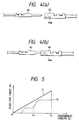
- Fig. 5 is an explanatory view of the relation between a push-out force and an engagement length in the first embodiment shown in Fig. 1;
- Fig. 6 is a plan view of the main portions of a second embodiment of a connector lock mechanism according to the invention;
- Fig. 7 is an explanatory view of the relation between a push-out force and an engagement length in the second embodiment shown in Fig. 6;
- Fig. 8 is an exploded perspective view of a third embodiment of a connector lock mechanism according to the invention;
- Fig. 9 is a longitudinal section view of an initial condition of the connector mutual engagement in the third embodiment shown in Fig. 8;
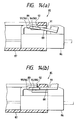
- Fig. 10 is a plan view of the main portions of the third embodiment shown in Fig. 8, showing an operation for mutual engagement between male and female connectors, in particular, Fig. 10 (a) shows an initial condition of the connector mutual engagement, and Fig. 10 (b) shows a complete condition of the connector mutual engagement;
- Fig. 11 is an exploded perspective view of a fourth embodiment of a connector lock mechanism according to the invention;
- Fig. 12 is a plan view of the main portions of the fourth embodiment shown in Fig. 11, showing an operation for mutual engagement between male and female connectors in the fourth embodiment, in particular, Fig. 12 (a) shows an initial condition of the connector mutual engagement, and Fig. 12 (b) shows a complete condition of the connector mutual engagement;
- Fig. 13 is an exploded perspective view of a fifth embodiment of a connector lock mechanism according to the invention;
- Fig. 14 is a longitudinal section view of the fifth embodiment shown in Fig. 13, showing a partially engaged condition between male and female connectors in the fifth embodiment;
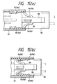
- Fig. 15 is a plan view of the main portions of the fifth embodiment shown in Fig. 13, in particular, Fig. 15 (a) shows an initial condition of mutual engagement between male and female connectors in the fifth embodiment, and Fig. 15 (b) shows a complete condition of the mutual engagement between the male and female connectors;
- Fig. 16 is an exploded perspective view of a sixth embodiment of a connector lock mechanism according to the invention;
- Fig. 17 is a longitudinal section view of the sixth embodiment shown in Fig. 16, showing a state thereof before the male and female connectors thereof are engaged together;
- Fig. 18 is a longitudinal section view of the sixth embodiment shown in Fig. 16, showing a partially engaged condition of the mutual engagement between the male and female connectors;
- Fig. 19 is a longitudinal section view of the sixth embodiment shown in Fig. 16, showing a completely engaged condition of the mutual engagement between the male and female connectors;
- Fig. 20 is an exploded perspective view of a seventh embodiment of a connector lock mechanism according to the invention;
- Fig. 21 is a longitudinal section view of the seventh embodiment shown in Fig. 20, showing a partially engaged condition of the mutual engagement between male and female connectors in the seventh embodiment;
- Fig. 22 is a longitudinal section view of the seventh embodiment shown in Fig. 20, showing a completely engaged condition of the mutual engagement between the male and female connectors;
- Fig. 23 is an explanatory view of the seventh embodiment shown in Fig. 20, showing the relation between a push-out force and an engagement length in the seventh embodiment;
- Fig. 24 is an exploded perspective view of an eighth embodiment of a connector lock mechanism according to the invention;
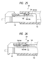
- Fig. 25 is a longitudinal section view of the eighth embodiment shown in Fig. 24, showing an intermediate condition of mutual engagement between male and female connectors in the eighth embodiment;
- Fig. 26 is a longitudinal section view of the eighth embodiment shown in Fig. 24, showing a completely engaged condition of the mutual engagement between the male and female connectors;
- Fig. 27 is an explanatory view of the eighth embodiment shown in Fig. 24, showing the relation between a push-out force and an engagement length in the eighth embodiment;
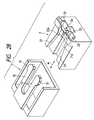
- Fig. 28 is a perspective view of male and female connectors, showing a conventional connector lock mechanism; and,
- Fig. 29 is a perspective view of the conventional connector lock mechanism shown in Fig. 28, showing a partially engaged condition of mutual engagement between male and female connectors in the conventional connector lock mechanism.
-
- Now, description will be given hereinbelow in detail of the preferred embodiments of a connector lock mechanism according to the invention with reference to the accompanying drawings.
- At first, description will be given below of a first embodiment of a connector lock mechanism according to the invention with reference to Figs. 1 to 5. In particular, Fig. 1 is an exploded perspective view of the first embodiment of a connector lock mechanism according to the invention; Fig. 2 is a perspective view of the main portions of a female connector shown in Fig. 1; Fig. 3 is an explanatory view of the operation of the first embodiment shown in Fig. 1; Fig. 4 is an explanatory view of the operation of the mutually connected condition between male and female terminals which produce the contact resistance when they are engaged together; and Fig. 5 is an explanatory view of variations in push-out forces which are caused to occur in a connector removing mechanism employed in the first embodiment shown in Fig. 1.
- A
connector lock mechanism 31 according to the first embodiment of the invention comprises a set of male andfemale connectors male connector 32, includes a pair offlexible arms male connector 32 can be engaged with theother connector 33 or female connector 33 (in Fig. 1, in a direction of an arrow A) and also which include engagingportions 38 respectively formed in their respective leading end portions thereof. Themale connector 32 also includes twoterminal storage chambers 32a therein in which two female-type terminals are respectively stored and retained. - The two
flexible arms male connector 32 and then extend toward the front end side thereof, while the rising base portions of theflexible arms flexible arms male connector 32 and extend parallel to each other. Further, the engagingportions 38 of theflexible arms male connector 32 from the respective leading end portions of their associatedflexible arms portions 38 includes a tapered surface which is gradually inclined outwardly from the front end side of the connector housing toward the rear end side thereof. - On the other hand, the other connector, that is, the
female connector 33, comprises a pair of arm guide surfaces 40 and 41 which respectively include securing means 43. The pair of arm guide surfaces 40 are capable of flexing theflexible arms engaging portions 38 of themale connector 32 to thereby lock the mutually engaged condition of the male and female connectors. Thefemale connector 33 stores and holds therein two male-type terminals which respectively correspond to thepartner male connector 32. - Also, as shown in Figs. 2 and 3, the two arm guide surfaces 40 and 41 of the
female connector 33 are respectively formed in the upper portions of the two inner side surfaces of the connector housing in such a manner that their associatedengaging portions male connector 32 can contact them when the two connectors are engaged with each other. The arm guide surfaces 40 and 41 respectively include tapered surfaces which are able to flex their associatedflexible arms engaging portions 38 of themale connector 32. - Next, description will be given below of an engaging operation to be executed for the mutual engagement of the above-mentioned male and
female connectors - At first, in the initial stage of the connector engagement, as shown in Figs. 3a and 4a, a male-
type terminal 45 stored within thefemale connector 33 is not in contact with a female-type terminal 46 stored within themale connector 32, that is, the twoterminals - If the mutual engagement between the male and female connectors advances to a certain degree, then, as shown in Figs. 3b and 4b, the male- and female-
type terminals portions 38 of themale connectors 32 are respectively engaged with the securing means 43 of thefemale connectors 33, the male- and female-type terminals connectors - Also, when the engaging
portions 38 of the twoflexible arms male connector 32 are respectively engaged with the securing means 43 of thefemale connector 33, the flexed conditions of the twoflexible arms flexible arms flexible arms - In the
connector lock mechanism 31 according to the present embodiment, the twoflexible arms connector removing mechanism 48. In other words, the presentconnector removing mechanism 48 is composed of the twoflexible arms male connector 32 and function as flexible elastic pieces, and the two arm guide surfaces 40, 41 which are formed integrally with thefemale connector 33 and function as push-out guide surfaces. Additionally, when the two, male and female, connectors are engaged together, the two arm guide surfaces 40, 41 serving as the push-out guide surfaces deform elastically the twoflexible arms - Referring now to the above in more detail, the inclination angles of the
flexible arms connector removing mechanism 48 is larger than mutual contact resistance caused by and between the male- and female-type terminals - As shown in Fig. 5, the characteristic line F1 of the
connector removing mechanism 48 shows the relation between the push-out force F and connector mutual engagement length L, whereas a characteristic curved line G1 shows the relation between the mutual contact resistance of the male andfemale terminals - The push-out force F that is generated by the
connector removing mechanism 48 is a reaction force which is given from the arm guide surfaces 40, 41 and increases up to a level just before the connector mutual engagement length L reaches a locked condition, that is, a condition shown by a preset length LE (see Fig. 3c). - Also, the mutual contact resistance G between the male- and female-
type terminals contact spring 46a disposed within the female-type terminal 46 begins to make contact with the male-type terminal 45. - As described above, in the
connector lock mechanism 31 according to the present embodiment, when a set of male andfemale connectors connector removing mechanism 48 generates the push-out force F which pushes the male andfemale connectors connector removing mechanism 48 is set larger than the mutual contact resistance caused by and between the male andfemale terminals female terminals - Therefore, the present
connector lock mechanism 31 is surely able to detect the mutually partially engaged condition between the male and female connectors and thus is surely able to prevent the possible overlooking of such connector partially engaged condition. - Also, since the
flexible arms connector removing mechanism 48 are all formed integrally with their associated connector housings, when compared with the conventional connector lock mechanism which uses separate parts such as compression springs or the like, according to the present connector lock mechanism, the number of parts required in the connectors as well as the number of assembling steps thereof can be reduced, which makes it possible not only to secure the reliability of the connectors but also to reduce the manufacturing costs thereof. - Further, according to the present embodiment, the
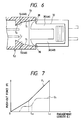
flexible arms connector removing mechanism 48, while the arm guide surfaces 40 and 41 also serve as the push-out guide surfaces of theconnector removing mechanism 48. Therefore, the structures of the respective connectors can be simplified, which makes it possible to enhance the moldability thereof as well as the yield rate of the products. - Next, description will be given below in detail of a second embodiment of a connector lock mechanism according to the invention with reference to Figs. 6 and 7. In particular, Fig. 6 is an explanatory view of the operation of a connector lock mechanism according to the second embodiment of the invention, while Fig. 7 is an explanatory view of variations in the push-out force of a connector removing mechanism according to the second embodiment.
- As shown in Fig. 6, in a
connector lock mechanism 51 according to the second embodiment, the arm guide surfaces 40 and 41 employed in theconnector lock mechanism 31 according to the first embodiment of the invention are improved, and the remaining portions of theconnector lock mechanism 51 are similar in structure those of the first embodiment. - That is, according to the present embodiment, the
flexible arms portions 38 respectively provided in themale connector 32 are the same as in the first embodiment, while theflexible arms connector removing mechanism 48. In afemale connector 53 which is an engaging partner connector of the male connector, there are formed arm guide surfaces 54 and 55 which are capable of flexing theflexible arms female connectors connector removing mechanism 48. - Referring in detail to the structure of the arm guide surfaces 54 and 55 according to the present embodiment, the inclination angles of the arm guide surfaces 54 and 55 functioning as the push-out guide surfaces are changed in their respective intermediate portions in order that, within the mutually engaged range of the male and
female connectors - In other words, the arm guide surfaces 54 and 55 serving as the push-out guide surfaces are each composed of a first tapered surface T1 which is disposed in the front portion of the associated guide surface and is smoothly inclined, and a second tapered surface T2 which is disposed in the rear portion of the associated guide surface and is steeply inclined. Since the arm guide surfaces 54 and 55 are each composed of such two tapered surfaces having different inclination angles, the push-out force F to be generated by the
connector removing mechanism 48 provides a characteristic line F2 as shown in Fig. 7. - As described above, in the
connector lock mechanism 51 according to the present embodiment, the inclination angles of the arm guide surfaces 54 and 55 functioning as the push-out guide surfaces of theconnector removing mechanism 48 are changed in their respective intermediate portions. For this reason, in the unconnected range in which the mutual contact resistance between the male and female terminals is not present, the push-out force F to be generated by theconnector removing mechanism 48 can be controlled to a minimum. This not only can minimize an operation force necessary for mutual engagement between the male and female connectors but also makes it possible to carry out an operation for mutual engagement between the connectors with higher efficiency. - Next, description will be given below in detail of a third embodiment of a connector lock mechanism according to the invention with reference to Figs. 8 to 10. In particular, Fig. 8 is an exploded perspective view of the third embodiment of a connector lock mechanism according to the invention, Fig. 9 is a longitudinal section view of an initial condition of the connector engagement in the third embodiment shown in Fig. 8, and Fig. 10 is an explanatory view of an operation for mutual engagement between the male and female connectors in the third embodiment shown in Fig. 8.
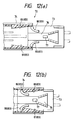
- Specifically, a
connector lock mechanism 57 according to the present embodiment relates to a set of male andfemale connectors male connector 59, includes a singleflexible arm 62 formed in such a manner as to extend along a direction thereof in which themale connector 59 can be engaged with the other connector, namely, thefemale connector 60, while theflexible arm 62 includes an engagingportion 63 formed integrally therewith. Themale connector 59 further includes twoterminal storage chambers 59a which are formed in the width direction of themale connector 59 and are capable of storing therein their respective female-type terminals. - The
flexible arm 62 is structured such that it rises up from the rear end side of the housing of themale connector 59 and then extends toward the front end side thereof. Also, the engagingportion 63 is a projection which is provided in the leading end portion of theflexible arm 62 in such a manner as to project upwardly, while the upwardly projecting length of the engagingportion 63 increases gradually from the front end side of the connector housing toward the rear end side thereof. - On the other hand, the other connector, namely, the
female connector 60 includes anarm guide surface 65 capable of downwardly flexing theflexible arm 62 until the mutual engagement length between the two connectors reaches a preset length, and securing means 66 which, when the connector mutual engagement length reaches the preset length, can secure the engagingportion 63 to thereby lock the connector mutually engaged condition. The arm guide surfaces 65 and securing means 66 are both formed integrally with thefemale connector 60. Thefemale connector 60 also has two male-type terminals which respectively correspond to the female-type terminals stored within themale connector 59. - As shown in Fig. 9, the
arm guide surface 65 is disposed in the inner surface of the upper wall of thefemale connector 60 in such a manner that, when the male andfemale connectors portion 63 can be contacted with thearm guide surface 65. In operation, thearm guide surface 65 flexes theflexible arm 62 downwardly as the connector mutual engagement advances. Also, the securing means 66 consists of a rectangular-shaped securing hole which is formed in the rear end portion of thearm guide surface 65 in such a manner that the engagingportion 63 can be fitted into the securinghole 66. - If the engaging
portion 63 of theflexible arm 62 is engaged with the securing means 66 of thefemale connector 60, the flexedflexible arm 62 returns to its original condition. When the engagingportion 63 is engaged with the securing means 66, the respective engaging surfaces thereof prevent the male and female connectors from moving in their mutually removing directions because the engaging surfaces extend at right angles to the mutually engaging directions of the male and female connectors, so that the mutually engaged condition of the male and female connectors can be locked. - The present
connector lock mechanism 57 further includes aconnector removing mechanism 70. The presentconnector removing mechanism 70 is composed of two flexibleelastic pieces 68 respectively formed integrally with themale connector 59, and two push-out guide surfaces 69 which are formed integrally with thefemale connector 60 and also which are capable of elastically deforming their associated flexibleelastic pieces 68 in the connector mutual engagement to thereby generate a push-out force pushing back themale connector 59 in the engagement removing direction. - The two flexible
elastic pieces 68 are respectively formed in such a manner that they project from the two side surfaces of theflexible arm 62 located near to the leading end portion thereof. As shown in Fig. 9, the two push-out guide surfaces 69 are respectively provided on the two side surfaces of the upper portion of the housing of thefemale connector 60 at the height position where their associated flexibleelastic pieces 68 can be contacted with the push-out guide surfaces 69 when theflexible arm 62 is flexed downwardly by thearm guide surface 65. - Also, as shown in Fig. 10a, the two push-out guide surfaces 69 are respectively tapered surfaces which are capable of flexing a pair of flexible
elastic pieces - Further, according to the present
connector removing mechanism 70, the elasticity of the flexibleelastic pieces 68 and the inclination angles of the push-out guide surfaces 69 are set in such a manner that the push-out force to be generated by the flexing of the flexibleelastic pieces 68 should be larger than the mutual contact resistance between the male- and female-type terminals respectively stored within their associated connectors. - As shown in Fig. 10b, when the connector mutual engagement length reaches a preset length and thus the engaging
portion 63 is engaged with the securing means 66, the flexibleelastic pieces 68 pass beyond the rear ends of their associated push-out guide surfaces 69 so that they are free from the pressures of their associated push-out guide surfaces 69. By the way, the push-out force F to be generated by theconnector removing mechanism 70 has the same characteristic line as the characteristic line F1 shown in Fig. 5. - As described above, in the
connector lock mechanism 57 according to the present embodiment, when a set of male andfemale connectors connector removing mechanism 70 generates the push-out force which pushes the set of male andfemale connectors connector removing mechanism 70 is set larger than the mutual contact resistance between the male- and female-type terminals respectively stored within their associated connectors, in a partially engaged condition where the male and female connectors are partially engaged with each other, the two connectors are both pushed away from each other at least until the mutually connected condition between the male- and female-type terminals is removed. This makes it possible to detect the partially engaged condition between the male and female connectors positively, thereby being able to surely prevent the possible overlooking of the partially engaged condition. - Also, because the flexible
elastic pieces 68 and push-out guide surfaces 69 forming theconnector removing mechanism 70 are respectively formed integrally with their associated connector housings, when compared with the conventional connector removing mechanism using separate parts such as compression springs, the number of parts required in the connectors as well as the number of assembling steps thereof can be reduced, which makes it possible to reduce the manufacturing costs of the connectors. - Next, description will be given below in detail of a fourth embodiment of a connector lock mechanism according to the invention with reference to Figs. 11 and 12. In particular, Fig. 11 is an exploded perspective view of the fourth embodiment of a connector lock mechanism according to the invention, and Fig. 12 is an explanatory view of an operation for mutual engagement between the male and female connectors in the fourth embodiment shown in Fig. 11.
- Specifically, a
connector lock mechanism 72 according to the present embodiment comprises a set of male andfemale connectors male connector 73 includes a singleflexible arm 76 formed in such a manner as to extend along a direction thereof in which themale connector 73 can be engaged with the other connector, namely, thefemale connector 74, while theflexible arm 76 includes an engagingportion 77 formed integrally therewith. Theflexible arm 76 is provided on the housing of themale connector 73 in such a manner that it rises up from the rear end side of themale connector 73 housing and then extends toward the front end side thereof. - The engaging
portion 77 consists of a projection which is formed on theflexible arm 76 in such a manner as to project upwardly therefrom, while the upwardly projecting length of the engagingportion 77 increases gradually from the front end side of the connector housing toward the rear end side thereof. The presentmale connector 73 includes, in the width direction thereof, twoterminal storage chambers 73a which are capable of storing their associated female-type terminals therein. - On the other hand, the other connector, namely, the
female connector 74 includes anarm guide surface 78 capable of flexing theflexible arm 76 until the mutual engagement length between the male and female connectors reaches a preset length. Thearm guide surface 78 includes securing means 79 which is formed integrally with thearm guide surface 78 and also which, when the connector mutual engagement length reaches the preset length, can secure the engagingportion 77 to thereby lock the connector mutually engaged condition. Thearm guide surface 78 is formed in the inner upper surface of the housing of thefemale connector 74 in such a manner that the engagingportion 77 can be contacted with thearm guide surface 78 when the male andfemale connectors arm guide surface 78 is able to flex theflexible arm 76 as the mutual engagement between the male and female connectors advances. Also, the engagingmeans 79 consists of a rectangular-shaped securing hole which is formed in the rear end portion of thearm guide surface 78 in such a manner that the engagingportion 77 can be engaged with the engagingmeans 79. Naturally, thefemale connector 74 includes two male-type terminals which correspond the female-terminals stored within themale connector 73. - In the mutual engagement between the above-structured male and
female connectors portion 77 of theflexible arm 76 of themale connector 73 is engaged with the securing means 79 of thefemale connector 74, theflexible arm 76 is returned from the flexed condition to its original condition. And, if the engagingportion 77 is engaged with the securing means 79, then their respective engaging surfaces prevent the male and female connectors from moving in their mutually removing directions because they intersect at right angles to the connector mutual engaging direction, so that the mutually engaged condition between the male and female connectors can be locked. - In the
connector lock mechanism 72 according to the present embodiment, there is provided aconnector removing mechanism 83. In particular, the presentconnector removing mechanism 83 is composed of two flexibleelastic pieces 80 respectively formed integrally with themale connector 73, and two push-out guide surfaces 81 respectively formed integrally with thefemale connector 74 and also, when the male and female connectors are operated for their mutual engagement, capable of elastically deforming their associated flexibleelastic pieces 80 to thereby generate a push-out force which pushes the male and female connectors in their mutually removing directions where the connector mutual engagement can be removed. - The above-mentioned flexible
elastic pieces 80 are respectively provided on the two sides of theflexible arm 76 of the housing of themale connector 73 in such a manner as to project directly therefrom, while the push-out guide surfaces 81 are respectively formed on the two side surfaces of the housing of thefemale connector 74 at such height position as their associated flexibleelastic pieces 80 can be contacted with the push-out surfaces 81. - As shown in Fig. 12, the push-out guide surfaces 81 are tapered surfaces which are capable of flexing their associated flexible
elastic pieces 80 inwardly as the connector mutual engagement advances. - In the above-mentioned
connector removing mechanism 83, the elasticity of the flexibleelastic pieces 80 and the inclination angles of the push-out guide surfaces 81 are set in such a manner that the push-out force to be generated by the flexing of the flexible elastic pieces is larger than the mutual contact resistance caused by and between the male and female terminals. - When the mutual engagement length between the connectors reaches a preset length and thus the engaging
portion 77 is engaged with the securing means 79, as shown in Fig. 12 (b), the flexibleelastic pieces 80 respectively pass through their associated push-out guide surfaces 81 while in contact therewith and are then secured to the rear ends of their associated push-out guide surfaces 81. It should be noted that the push-out force of the presentconnector removing mechanism 83 provides the same characteristic line as the characteristic line F1 shown in Fig. 5. - In the above-mentioned
connector lock mechanism 72 according to the present embodiment, when a set of male andfemale connectors connector removing mechanism 83 generates the push-out force which pushes the male and female connectors in their mutually removing directions where the male andfemale connectors connector removing mechanism 83 is set larger than the mutual contact resistance caused by and between the male- and female-type terminals respectively stored within their associated connectors, when the male and female connectors are partially engaged with each other, the male connector is pushed back in the removing direction at least until the mutually connected condition between the male- and female-type terminals is removed completely. This makes it possible to surely detect the half engagement between the male andfemale connectors - Also, since the flexible
elastic pieces 80 and push-out guide surfaces 81 forming the presentconnector removing mechanism 83 are respectively formed integrally with their associated connectors, when compared with the conventional connector removing mechanism which employs separate parts such as compression springs, the number of parts required in the connectors as well as the number of assembling steps thereof can be reduced, thereby being able to reduce the manufacturing costs thereof. - Next, description will be given below in detail of a fifth embodiment of a connector lock mechanism according to the invention with reference to Figs. 13 to 15. In particular, Fig. 13 is an exploded perspective view of the fifth embodiment of a connector lock mechanism according to the invention, Fig. 14 is a longitudinal section view of the fifth embodiment shown in Fig. 13, showing a partially engaged condition between the male and female connectors, and Fig. 15 is an explanatory view of the operation of the mutual engagement between the male and female connectors in the fifth embodiment shown in Fig. 13.
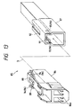
- Specifically, a
connector lock mechanism 85 according to the present embodiment relates to a set of male andfemale connectors male connector 86 includes a singleflexible arm 88 formed in such a manner as to extend along a direction thereof (in Fig. 13, in the direction of an arrow D) in which themale connector 86 can be engaged with the other connector, namely, thefemale connector 87, while theflexible arm 88 includes an engaging portion 89 'formed integrally therewith. Theflexible arm 88 rises up from the front end side of themale connector 86 housing and then extends toward the rear end side and, the engagingportion 89 of theflexible arm 88 projects upwardly from the upper surface of theflexible arm 88, while the projecting length of the engagingportion 89 increases gradually from the front end side of themale connector 86 housing toward the rear end side thereof. It is noted that the presentmale connector 86 includes in the width direction thereof twoterminal storage chambers 86a respectively capable of storing female-type terminals therein. - On the other hand, the other connector, namely, the
female connector 87 includes anarm guide surface 91 with securing means 92 formed integrally therewith. Thearm guide surface 91 is capable of flexing theflexible arm 88 until the mutual engagement length between the male and female connectors reaches a preset length. The securing means 92 of thearm guide surface 91, when the mutual engagement length reaches the present length, is capable of securing the engagingportion 89 of theflexible arm 88 to thereby lock the mutually engaged condition between the male and female connectors. Also, the securing means 92 consists of a rectangular-shaped securing hole which is formed in front of thearm guide surface 91 in such a manner that the engagingportion 89 of theflexible arm 88 can be fitted into the securing means 92. The presentfemale connector 87 stores and holds therein two male-type terminals which corresponds to the female-type terminals held within themale connector 86. - As shown in Fig. 14, the
arm guide surface 91 is formed on the side surface of the housing of thefemale connector 87 in such a manner that, when the male andfemale connectors portion 89 of theflexible arm 88 contact thearm guide surface 91. Theflexible arm 88 is gradually flexed downwardly as the connector mutual engagement advances. However, when the engagingportion 89 of theflexible arm 88 is engaged with the securing means 92 of thefemale connector 87, theflexible arm 88 is returned from the flexed condition back to its original condition. In this operation, because the engaging surfaces thereof intersect at right angles to the connector engaging direction, they prevent the male and female connectors from moving in their mutually removing directions to thereby lock the mutually engaged condition between the male and female connectors. - In the
connector lock mechanism 85 according to the present embodiment, one connector, namely, themale connector 86, includes a pair of flexibleelastic pieces 94 respectively formed integrally with themale connector 86. The pair of flexibleelastic pieces 94 are respectively arranged in such a manner that they project laterally from the their associated side surfaces of theflexible arm 88 of themale connector 86. - Also, the other connector, namely, the
female connector 87, includes a pair of push-out guide surfaces 95 respectively formed integrally with thefemale connector 87. The push-out guide surfaces 95, when the male andfemale connectors elastic pieces 94 to thereby generate a push-out force which pushes back the male and female connectors in their mutually removing directions. The push-out guide surfaces 95 and flexibleelastic pieces 94 cooperate together in forming aconnector removing mechanism 96. - As shown in Figs. 13 and 15, the push-out guide surfaces 95 are respectively formed on the two side surfaces of the
female connector 87 at such a height that, while theflexible arm 88 is flexed, the flexibleelastic pieces 94 on theflexible arm 88 can be respectively contacted with the push-out guide surfaces 95. Further, as shown in Figs. 14 (a) and 15 (a), the push-out guide surfaces 95 respectively consist of tapered surfaces which are able to flex their associated flexibleelastic pieces 94 inwardly as the connector engagement advances. - In a state where the flexible
elastic pieces 94 are held in contact with their associated push-out guide surfaces 95 during the flexed condition of theflexible arm 88, there is always generated the push-out force which pushes back the male and female connectors in their mutually removing directions. - Here, in the
connector removing mechanism 96 according to the present embodiment, the elasticity of the flexibleelastic pieces 94 and the inclination angles of the push-out guide surfaces 95 are set in such a manner that the push-out force to be generated by the flexing of the flexibleelastic pieces 94 is larger than the mutual contact resistance caused by and between male-type and female-type terminals which are respectively stored within the two connectors. - When the male and female connectors are engaged together completely, that is, when the mutual engagement length between the male and female connectors reaches a preset length, the engaging
portion 89 of theflexible arm 88 is engaged with the securing means 92 of thearm guide surface 91 and the flexed condition of theflexible arm 88 is removed. In addition, as shown in Figs. 14 (b) and 15 (b), the flexibleelastic pieces 94 pass beyond the end of the push-outguide surface 95 and is thereby removed from the push-out guide surface 95 (in Fig. 14 (b), the former is removed upwardly from the latter) and, at the same time, the push-out force acting in the connectors mutually removing directions is also removed. Therefore, in the connector complete engagement, the flexibleelastic pieces 94 are returned back to their original conditions together with theflexible arm 88, which makes it possible to prevent the possible fatigue of theflexible pieces 94 caused by holding theflexible pieces 94 in the flexed condition for a long period of time. By the way, the push-out force to be generated by theconnector removing mechanism 96 provides the same characteristic line as the characteristic line F1 shown in Fig. 5. - As described above, in the
connector lock mechanism 85, when the set of male andfemale connectors connector removing mechanism 96 always applies to the male andfemale connectors connector removing mechanism 96 is set larger than the mutual contact resistance between the male-type and female-type terminals which are respectively stored within the two connectors, when the two connectors are partially engaged with each other, the two connectors are pushed back in their mutually removing directions at least until the mutually connected condition between the male- and female-type terminals is removed. Therefore, the presentconnector lock mechanism 85 is surely able to detect the partially engaged condition between the male and female connectors without fail. - Also, the flexible
elastic pieces 94 and push-out guide surfaces 95 forming the presentconnector removing mechanism 96 are respectively provided in their associated connectors in such a manner that they are formed integrally therewith. That is, when compared with the conventional connector removing mechanism which uses separate parts such as compression springs or the like, the presentconnector removing mechanism 96 can reduce the number of parts required in the connectors as well as the number of assembling steps thereof, which in turn makes it possible to reduce the manufacturing costs thereof. - Next, description will be given below in detail of a sixth embodiment of a connector lock mechanism according to the invention with reference to Figs. 16 to 19. In particular, Fig. 16 is an exploded perspective view of the sixth embodiment of a connector lock mechanism according to the invention, Fig. 17 is a longitudinal section view of male and female connectors respectively shown in Fig. 16, Fig. 18 is a longitudinal section view of the sixth embodiment, showing a mutually partially engaged condition between the male and female connectors shown in Fig. 16, and Fig. 19 is a plan view of the main portions of the sixth embodiment shown in Fig. 16, showing a completely engaged condition between the male and female connectors thereof.
- Specifically, a
connector lock mechanism 98 according to the present embodiment relates to a set of male andfemale connectors male connector 99 includes a pair offlexible arms male connector 99 can be engaged with the other connector, namely, thefemale connector 100, while each of theflexible arms 102 includes an engagingportion 103 which is formed integrally therewith. Each of the presentflexible arms 102 is provided on the housing of themale connector 99 in such a manner that it rises up from the front end side of themale connector 99 housing and then extends toward the rear end side thereof. The free end portions of the twoflexible arms 102, which are situated in the rear end side of themale connector housing 99, are connected together to thereby form an operation portion which can be used to remove the locking of the mutual engagement between the male and female connectors. - Also, the engaging
portions 103 of theflexible arms 102 are respectively formed in such a manner as to project from the outer surfaces of their associatedflexible arms 102 toward the male connector housing side, while the projecting lengths thereof increase gradually from the front end side of the male connector housing toward the rear end side thereof. By the way, the presentmale connector 99 includes in the width direction thereof twoterminal storage chambers 99a which are capable of storing female-type terminals therein. - On the other hand, the other connector, namely, the
female connector 100 comprises a pair of arm guide surfaces 104 respectively which are capable of flexing their associatedflexible arm 102 until the mutual engagement length between the male and female connectors reaches a preset length. The arm guide surfaces 104 respectively include securing means 105 which, when the connector mutual engagement length reaches the preset length, can secure their associatedengaging portions 103 to thereby lock the mutually engaged condition between the two connectors. The present securing means 105 respectively consist of stepped portions which are formed in the rear end portions of their associated arm guide surfaces 104 in such a manner that their associatedengaging portions 103 can be engaged with the securing means 105. - As shown in Fig. 19, the two arm guide surfaces 104 are respectively formed on the housing side surfaces of the
female connector 100 in such a manner that, when the male andfemale connectors portions 103 of the twoflexible arms 102 can be contacted with the arm guide surfaces 104. As the mutual engagement between the male and female connectors advances, the arm guide surfaces 104 gradually flex their respectiveflexible arms 102 inwardly. - When the engaging
portions 103 of theflexible arms 102 are respectively engaged with the securing means 105 of thefemale connector 100, theflexible arms 102 are returned from their flexed conditions back to their original conditions. If the engagingportions 103 are engaged with securing means 105, then the engaging surfaces thereof prevent the male and female connectors from moving in their mutually removing directions because the engaging surfaces intersect at right angles to the connector engaging direction, so that the mutually engaged condition between the male and female connectors can be locked. - Now, in the
connector lock mechanism 98 according to the present embodiment, the pair offlexible arms connector removing mechanism 107. That is, the presentconnector removing mechanism 107 is composed of the pair offlexible arms male connector 99 and are used as flexible elastic pieces, and the pair of arm guide surfaces 104, 104 which are formed integrally with thefemale connector 100 and are used as push-out guide surfaces. - The arm guide surfaces 104 serving as the push-out guide surfaces, when the male and female connectors are engaged with each other, elastically deform their respective
flexible arms 102 serving as the flexible elastic pieces to thereby generate a push-out force which acts on the male and female connectors in a direction where they are separated or removed from their mutually engaged condition. - In more detail, the elasticity of the pair of
flexible arms 102 and the inclination angles of the pair of arm guide surfaces 104 are set such that the push-out force to be generated by theconnector removing mechanism 107 according to the present embodiment is larger than the mutual contact resistance caused by and between male- and female-type terminals respectively stored within the two connectors. - Also, on the respective inner side surfaces of the pair of
flexible arms preventive pieces 109 in such a manner that they are formed integrally with their associatedflexible arms 102. As shown in Figs. 17 and 18, if an operator tries to engage the male and female connectors with each other while theflexible arms 102 are flexed in the locking removed condition, then the wrong operationpreventive pieces 109 interfere with anobstacle plates 110 which is disposed within the housing of thefemale connector 100, thereby preventing the male and female connectors from being engaged with each other. As shown in Fig. 16, theobstacle plate 110 is arranged on the upper wall of the female connector housing in parallel thereto through asupport wall 111 which hangs down from the upper wall portion of the housing of thefemale connector 100. - As shown in Figs. 17 and 18, the
rear end face 110a of theobstacle plate 110 and the rear end faces 109a of the wrong operationpreventive pieces 109 are respectively chamfered into smoothly curved shapes. That is, if the twoflexible arms preventive pieces 109 andobstacle plate 110 are contacted with each other, so that the wrong operationpreventive pieces 109 are allowed to slide into below theobstacle plate 110; that is, the movement of the male and female connectors in their mutually removing directions is not prevented by theobstacle plate 110. - As described above, in the
connector lock mechanism 98 according to the present embodiment, when the set of male andfemale connectors connector removing mechanism 107 applies to the male andfemale connectors connector removing mechanism 107 is set larger than the mutual contact resistance between the male-type and female-type terminals which are respectively stored within the male and female connectors, when the male and female connectors are partially engaged with each other, the male and female connectors are pushed back in their mutually removing directions at least until the mutually connected condition of the male and female terminals is removed. Therefore, the presentconnector lock mechanism 98 is surely able to detect the partially engaged condition between the male and female connectors without fail. - Also, the
flexible arms 102 serving as the flexible elastic pieces and arm guide surfaces 104 serving as the push-out guide surfaces, which respectively cooperate in forming the presentconnector removing mechanism 107, are respectively provided in their associated connectors in such a manner that they are formed integrally therewith. Therefore, when compared with the conventional connector removing mechanism which uses separate parts such as compression springs or the like, the presentconnector removing mechanism 107 can reduce the number of parts required in the connectors as well as the number of assembling steps thereof, which in turn makes it possible to reduce the manufacturing costs thereof. - Further, since the wrong operation
preventive pieces 109 are formed integrally with their associatedflexible arms 102, even if the mutually engaging operation between the male and female connectors is executed in error in a state where theflexible arms 102 are flexed in the locking removed condition, there is surely prevented the possibility that the connector mutually engaging operation can continue in a state where the positions of the flexible elastic pieces are deviated from the positions of the push-out guide surfaces, that is, in a state where the presentconnector removing mechanism 107 cannot operate normally. This can improve the reliability of theconnector removing mechanism 107. - Next, description will be given below in detail of a seventh embodiment of a connector lock mechanism according to the invention with reference to Figs. 20 to 23. In particular, Fig. 20 is an exploded perspective view of the seventh embodiment of a connector lock mechanism according to the invention; Fig. 21 is a longitudinal section view of male and female connectors respectively shown in Fig. 20, showing a partially engaged condition between them; Fig. 22 is a longitudinal section view of the male and female connectors shown in Fig. 20, showing a completely engaged condition between them; and Fig. 23 is an explanatory view of the relation between a push-out force to be generated by a connector removing mechanism and the length of the mutual engagement between the male and female connectors in the seventh embodiment shown in Fig. 20.
- Specifically, a
connector lock mechanism 115 according to the present embodiment relates to a set of male andfemale connectors male connector 116 includes a pair offlexible arms male connector 116 can be engaged with the other connector, namely, thefemale connector 117, while theflexible arms 119 include between them an engagingportion 120 which is formed integrally therewith. Each of theflexible arms 119 is provided on the housing of themale connector 116 in such a manner that it rises up from the front end side of themale connector 116 housing and then extends toward the rear end side thereof. The free end portions of the twoflexible arms 119 which are situated in the rear end side of the male connector housing are connected together to thereby form an operation portion which can be used to remove the locking of the mutual engagement between the male and female connectors. The engagingportion 120 of theflexible arms 119 is formed in such a manner as to project from the outer surfaces of theflexible arms 119 toward the male connector housing side, while the upwardly projecting length thereof increases gradually from the front end side of the male connector housing toward the rear end side thereof. It is noted that the presentmale connector 116 includes in the width or lateral direction thereof twoterminal storage chambers 116a which are capable of storing female-type terminals therein. - On the other hand, the other connector, namely, the
female connector 117 comprises anarm guide surface 121 which is capable of flexing theflexible arms 119 until the mutual engagement length between the male and female connectors reaches a preset length, while thearm guide surface 121 includes securing means 105 which, when the connector mutual engagement length reaches the preset length, is capable of securing the engagingportion 120 of theflexible arms 119 to thereby lock the mutually engaged condition between the male and female connectors. - As shown in Fig. 21, the
arm guide surface 121 is formed on the side surface of the housing of thefemale connector 117 in such a manner that, when the male andfemale connectors portion 120 of theflexible arms 119 contact thearm guide surface 121. In particular, thearm guide surface 121 is able to flex theflexible arms 119 gradually downwardly as the mutual engagement between the male and female connectors advances. The securing means 123 consists of a rectangular-shaped securing hole which is formed in the rear end portion of thearm guide surface 121 in such a manner that the engagingportion 120 can be engaged with the securing means 123. Thefemale connector 117 stores and holds therein two male-type terminals which correspond to the female-type terminals stored within themale connector 116. - As shown in Fig. 22, when the engaging
portion 120 of theflexible arms 119 is engaged with the securing means 123 of thefemale connector 117, theflexible arms 119 are returned from their flexed conditions back to their original conditions. At this time, since the engaging surfaces thereof extend at right angles to the engaging direction of the male and female connectors, they prevent the male and female connectors from moving in their mutually removing directions, so that the mutually engaged condition between the male and female connectors can be locked. - In the
connector lock mechanism 115 according to the present embodiment, not only the pair offlexible arms 119 including the engagingportion 120 between them and the pair ofarm guide surface 121 function as a firstconnector removing mechanism 125, but also the pair offlexible arms 119 and a pair of push-out guide surfaces 126 and 126 respectively formed in the two inner surfaces of thefemale connector 117 function as a secondconnector removing mechanism 127. - That is, the first
connector removing mechanism 125 is composed of the pair offlexible arms male connector 116 and serving as flexible elastic pieces, and the pair of arm guide surfaces 121 formed integrally with thefemale connector 117 and serving as push-out guide surfaces. The arm guide surfaces 121 functioning as the push-out guide surfaces, when the male and female connector are operated for their mutual engagement, can deform elastically theflexible arms 119 serving as the flexible elastic pieces downwardly through the engagingportion 120 thereof to thereby generate a push-out force which removes the mutually engaged condition between the male and female connectors. - Also, the second
connector removing mechanism 127 is structured such that, when the male and female connector are operated for their mutual engagement, two push-outprojections 129 respectively provided on the respective outer side surfaces of the twoflexible arms 119 are contacted with their associated push-out guide surfaces 126 to thereby elastically deform theflexible arms 119 inwardly. The elastic deformation of theflexible arms 119 generates the push-out force which removes the mutually engaged condition between the male and female connectors. Therefore, the total of the push-out force to be generated by the firstconnector removing mechanism 125 and the push-out force to be generated by the secondconnector removing mechanism 127 provides the actually obtainable push-out force. - In the
connector removing mechanisms flexible arms connector removing mechanism 125 and the push-out force to be generated by the secondconnector removing mechanism 127 is larger than the mutual contact resistance caused by and between male- and female-type terminals respectively held within their associated connectors. - As described above, in the
connector lock mechanism 115 according to the present embodiment, when the set of male andfemale connectors connector removing mechanism female connectors connector removing mechanisms - Therefore, the present
connector lock mechanism 115 is surely able to detect the partially engaged condition between the male and female connectors without fail. - Also, the flexible elastic pieces and push-out guide surfaces, which respectively cooperate in forming the present
connector removing mechanisms connector removing mechanism - Further, since the flexible elastic pieces and push-out guide surfaces respectively cooperating in forming the present connector removing mechanisms are provided in two or more sets, for example, if the respective sets of flexible elastic pieces and push-out guide surfaces are shifted in the operation timings from one another, the push-out force to be generated by the present connector removing mechanisms can be made to vary. Also, if the two or more sets of flexible elastic pieces and push-out guide surfaces are operated simultaneously, then a large push-out force can be obtained easily and, therefore, even if the number of terminals to be stored within the respective connectors is large, the present connector removing mechanisms are surely able to provide a necessary and sufficient push-out force.
- It is noted that the push-out force that can be obtained when the operation timings of the first and second
connector removing mechanism - Next, description will be given below in detail of an eighth embodiment of a connector lock mechanism according to the invention with reference to Figs. 24 to 27. In particular, Fig. 24 is an exploded perspective view of the eighth embodiment of a connector lock mechanism according to the invention; Fig. 25 is a longitudinal section view of male and female connectors respectively shown in Fig. 24, showing a partially engaged condition between them; Fig. 26 is a longitudinal section view of the male and female connectors shown in Fig. 24, showing a completely engaged condition between them; and Fig. 27 is an explanatory view of the relation between a push-out force to be generated by a connector removing mechanism shown in Fig. 24 and the length of the mutual engagement between the male and female connectors.
- Specifically, a
connector lock mechanism 130 according to the present embodiment comprises a set of male andfemale connectors male connector 131 includes a pair offlexible arms male connector 131 can be engaged with the other connector, namely, thefemale connector 132, while the twoflexible arms 119 include an engagingportion 134 formed integrally therewith. Each of theflexible arm 119 is provided on the housing of themale connector 131 in such a manner that it rises up from the front end side of themale connector 131 housing and then extends toward the rear end side thereof. The respective free end portions of the twoflexible arms 119 which are situated in the rear end side of the male connector housing are connected together to thereby form an operation portion which can be used to remove the locking of the mutual engagement between the male and female connectors. - Also, the engaging
portion 134 is interposed between theflexible arms 119 and, as shown in Figs. 25 and 26, is formed in a curved surface in which the upwardly projecting length thereof increases gradually from the front end side of the housing of themale connector 131 toward the rear end side thereof. The presentmale connector 131 includes in the width direction thereof twoterminal storage chambers 131a which are capable of storing female-type terminals therein. - On the other hand, the other connector, namely, the
female connector 132 comprises anarm guide surface 135 which is capable of flexing theflexible arms 119 until the mutual engagement length between the male and female connectors reaches a preset length. Thearm guide surface 135 includes securing means 136 which, when the connector mutual engagement length reaches the preset length, can secure the engagingportion 134 of theflexible arms 119 to thereby lock the mutually engaged condition between the male andfemale connectors - As shown in Fig. 25, the
arm guide surface 135 is formed on the side surface of the housing of thefemale connector 132 in such a manner that, when the male andfemale connectors portion 134 of theflexible arms 119 contact thearm guide surface 135. In particular, thearm guide surface 135 is structured such that it can flex theflexible arms 119 gradually downwardly as the mutual engagement between the male and female connectors advances. Also, the securing means 136 consists of a stepped porti'on which is formed in the rear end portion of the arm guide surface135 in such a manner that the engagingportion 134 can be engaged with the securing means 136. It is noted that thefemale connector 132 stores and holds therein two male-type terminals which correspond to the female-type terminals stored within themale connector 131. - As shown in Fig. 26, when the engaging
portion 134 of theflexible arms 119 is engaged with the securing means 136 of thefemale connector 132, theflexible arms 119 are returned from the flexed conditions back to their respective original conditions. At this time, because the engaging surfaces thereof extend at right angles to the connector mutually engaging direction, the mutually engaged condition between the male and female connectors can be locked positively. - Also, in the
connector lock mechanism 130 according to the present embodiment, not only the pair offlexible arms arm guide surface 135 function as a firstconnector removing mechanism 125, but also the pair offlexible arms female connector 132 function as a secondconnector removing mechanism 140. - That is, the first
connector removing mechanism 138 is composed of the pair offlexible arms male connector 131 and serving as flexible elastic pieces, and thearm guide surface 135 formed integrally with thefemale connector 132 and serving as a push-out guide surface. And, thearm guide surface 135 functioning as the push-out guide surface, when the male and female connector are operated for their mutual engagement, elastically deforms theflexible arms 119 serving as the flexible elastic pieces downwardly through the engagingportion 134 thereof to thereby generate a push-out force which removes the mutually engaged condition between the male and female connectors. - Also, the second
connector removing mechanism 140 is structured such that, when the male and female connector are operated for their mutual engagement, the push-out guide surfaces 139 are allowed to press against two push-outprojections 142, which are respectively provided on and projected from the respective outer side surfaces of the twoflexible arms 119, inwardly to thereby elastically deform theflexible arms 119 inwardly. The elastic deformation of theflexible arms 119 can generate the push-out force which removes the mutually engaged condition between the male andfemale connectors - Therefore, the total of the push-out force to be generated by the first
connector removing mechanism 138 and the push-out force to be generated by the secondconnector removing mechanism 140 provides the actually obtainable push-out force. - Also, in the
connector removing mechanisms flexible arms arm guide surface 135 and push-out guide surfaces 139 are set in such a manner that the total of the push-out force to be generated by the firstconnector removing mechanism 138 and the push-out force to be generated by the secondconnector removing mechanism 140 is larger than the mutual contact resistance caused by and between the male- and female-type terminals respectively held within their associated connectors. - As described above, in the
connector lock mechanism 130 according to the present embodiment, when the set of male andfemale connectors connector removing mechanisms female connectors connector removing mechanisms female connectors connector lock mechanism 130 is surely able to detect the partially engaged condition between the male andfemale connectors - Also, the flexible elastic pieces and push-out guide surfaces, which respectively cooperate in forming the present
connector removing mechanisms connector removing mechanisms - It is noted that the push-out force that can be obtained when the operation timings of the first and second
connector removing mechanism - As has been described heretofore, according to the invention, there is provided a connector lock mechanism which comprises a connector removing mechanism. The present connector removing mechanism is composed of a flexible elastic piece formed integrally with one connector, and a push-out guide surface which is formed integrally with the other connector and also which, when the two connectors are operated for their mutual engagement, can deform the flexible elastic piece elastically to thereby generate a push-out force that separates the two connectors from each other in their mutually removing directions. And, the elasticity of the flexible elastic piece and the inclination angle of the push-out guide surface are set in such a manner that the push-out force to be generated by the present connector removing mechanism is larger than the mutual contact resistance caused by and between male- and female-type terminals which are respectively held within their associated connectors.
- Therefore, not only because, when a set of male and female connectors are operated for their mutual engagement, the present connector removing mechanism applies to the male and female connectors the push-out force which acts on the male and female connectors in directions where they are separated from each other, but also because the push-out force to be generated by the present connector removing mechanism is set larger than the mutual contact resistance caused by and between male- and female-type terminals within their associated connectors, if the male and female connectors are partially engaged, then the male and female connectors are pushed back in their mutually separating or removing directions at least until the connected condition between the male- and female-type terminals is removed. This makes it possible to surely detect the partially engaged condition between the male and female connectors without fail.
- Also, since the flexible piece and push-out guide surface cooperating together in forming the present connector removing mechanism are respectively formed integrally with their associated connectors, when compared with the conventional connector removing mechanism which uses separate parts such as compression springs, the present connector removing mechanism can reduce the number of parts required in the connectors as well as the number of assembling steps thereof, which in turn makes it possible to reduce the manufacturing costs thereof.
- Also, in the above-mentioned connector lock mechanism, preferably, the flexible arm may also serve as the flexible elastic piece and the arm guide surface may also serve as the push-out guide surface. That is, in the present preferred embodiment, the respective connectors can be simplified in structure, which in turn can enhance the moldability of the connectors as well as the yield of the products.
- Further, in the above-mentioned connector lock mechanism, preferably, within the range of the above-mentioned mutual engagement between the male and female connectors, the inclination angle of the push-out guide surface may be changed properly in the intermediate portion thereof in such a manner that a greater push-out force can be generated in the range of the mutual connection between the above-mentioned male- and female-type terminals than in the unconnected condition between the male- and female-type terminals. That is, in the thus structured preferred embodiment, in the unconnected condition between the male- and female-type terminals in which the mutual resistance between the male- and female-type terminals does not act, the push-out force to be generated by the connector removing mechanism can be controlled to a minimum, which makes it possible to save an operation force necessary for mutual engagement between the male and female connectors. Therefore, the operation for mutual engagement between the male and female connectors can be improved in efficiency.
- Still further, in the above-mentioned connector lock mechanism, preferably, the flexible elastic piece may be formed integrally with the flexible arm, and a wrong operation preventive piece, which is used to prevent the male and female connectors from being engaged with each other while the flexible arm is flexed in its locking removed condition, may be formed integrally with the flexible arm. That is, in the present preferred embodiment, even if the mutual engagement between the male and female connectors is executed in error while the flexible arm is flexed in its locking removed condition, the connector removing mechanism is prevented from operating normally in a condition where the position of the flexible elastic piece is shifted from the position of the push-out guide surface. Therefore, the mutual engagement between the male and female connectors due to the inadvertent flexing of the flexible arm can be prevented, thereby being able to enhance the reliability of the connector removing mechanism.
- Yet further, in the above-mentioned connector lock mechanism, preferably, the above-mentioned flexible elastic piece and push-out guide surface may be provided in two or more sets. That is, in the present preferred embodiment, if the operation timings of the respective sets of flexible elastic pieces and push-out guide surfaces are shifted from one another, then the push-out force to be generated by the connector removing mechanism can be made to vary.
- Also, if the two or more sets of flexible elastic pieces and push-out guide surfaces are operated simultaneously, then a large push-out force can be provided easily. Therefore, even if the number of terminals to be stored within the respective connectors is large, there can be obtained a necessary and sufficient push-out force.
- Moreover, in the above-mentioned connector lock mechanism, preferably, while the flexible arm is held in its flexed condition, a push-out force acting on the male and female connectors in their mutually removing directions may be always generated due to the flexed condition of the flexible elastic piece; and, if the male and female connectors are engaged with each other completely, then the flexed conditions of the flexible arm and flexible elastic piece may be removed, thereby being able to remove the push-out force acting on the male and female connectors in their mutually removing directions. Therefore, when the male and female connectors are completely engaged with each other, the flexible elastic piece, together with the flexible arm, can be returned to its original condition, which makes it possible to prevent the fatigue of the flexible elastic piece caused by the long flexed condition thereof.
Claims (20)
- A connector lock mechanism for locking the connected condition of a set of male and female connectors to be engaged with each other, the connector lock mechanism comprising:a flexible arm disposed on one of the male and female connectors and extending along a direction in which one connector can be engaged with the other connector;an engaging portion disposed on the flexible arm;an arm guide surface disposed on the other connector for flexing the flexible arm until the length of the mutual engagement between the two connectors reaches a preset length;a securing member disposed on the other connector, said securing member securing the engaging portion of the flexible arm to thereby prevent the two connectors from being removed from each other when the connector mutual engagement length reaches the preset length; anda connector removing mechanism including a flexible elastic piece formed integrally with said one connector and a push-out guide surface which is formed integrally with said other connector and also which, when said two connectors are operated for their mutual engagement, deforms said flexible elastic piece elastically to thereby generate a push-out force separating said two connectors from each other in their mutually removing directions, wherein the elasticity of said flexible elastic piece and the inclination angle of said push-out guide surface are set such that said push-out force generated by said connector removing mechanism is greater than contact resistance caused by mutual connection between male- and female-type terminals respectively held within their associated connectors.
- The connector lock mechanism of claim 1, wherein said flexible arm serves also as said flexible elastic piece and said arm guide surface serves also as said push-out guide surface.
- The connector lock mechanism of claim 1, wherein, in the range of the mutual engagement between said two connectors, the angle of said push-out guide surface is changed in the intermediate portion thereof so that a greater push-out force can be generated in the mutually connected range of said male- and female-type terminals than in the mutually unconnected range of said male- and female-type terminals.
- The connector lock mechanism of claim 1, wherein said flexible elastic piece is formed integrally with said flexible arm, and wherein said connector lock mechanism further comprises a wrong operation preventive piece formed integrally with said flexible arm, said wrong operation preventive piece preventing said two connectors from being engaged with each other while said flexible arm is flexed in a locking removed condition.
- The connector lock mechanism of claim 1, wherein said flexible elastic piece and said push-out guide surface are provided in at least two.
- The connector lock mechanism of claim 1, wherein, while said flexible arm is held in its flexed condition, the flexed condition of said flexible elastic piece generates a push-out force acting said two connectors in their mutually removing directions and, if said two connectors are completely engaged with each other, the flexed condition of said flexible arm and the flexed condition of said flexible elastic piece are removed, thereby removing said push-out force acting in said connectors mutually removing directions.
- A connector arrangement comprising:a first connector including a flexible arm disposed thereon; anda second connector including an arm guide member disposed on an inner surface thereof, said arm guide member having an inclined push-out guide surface for gradually deflecting the flexible arm as said connectors are engaged with each other, said deflection generating a push-out force separating said two connectors from each other in their mutually removing directions, wherein the elasticity of said flexible arm and the inclination angle of said push-out guide surface are set such that said push-out force generated thereby is greater than contact resistance caused by mutual connection between male- and female-type terminals respectively held within their associated connectors.
- The connector arrangement of claim 7, wherein said flexible arm includes an engaging portion which engages said arm guide member when said connectors are fully engaged.
- The connector arrangement of claim 7, further comprising a locking arm extending from said first connector and having a locking projection, and a securing member disposed on said second connector, said locking projection engaging said securing member when said connectors are fully engaged.
- The connector arrangement of claim 9, wherein said first connector includes a pair of said flexible arms and said second connector includes a pair of said arm guide members respectively mateable therewith.
- The connector arrangement of claim 10, wherein said flexible arms extend from said locking arm.
- The connector arrangement of claim 11, wherein said flexible arm includes an engaging portion which engages said arm guide member when said connectors are fully engaged.
- The connector arrangement of claim 7, wherein said first connector includes a pair of said flexible arms and said second connector includes a pair of said guide members respectively mateable therewith.
- The connector arrangement of claim 7, wherein a first portion of said inclined guide surface is inclined at a predetermined angle and a second portion is inclined at an angle greater than said predetermined angle.
- A connector arrangement comprising:a first connector including a flexible arm disposed thereon, said flexible arm having an engaging projection extending therefrom; anda second connector including an arm guide member disposed on an inner surface thereof, said arm guide member having an inclined push-out guide surface which is contacted by said engaging projection for gradually deflecting the flexible arm as said connectors are engaged with each other, said deflection generating a push-out force separating said two connectors from each other in their mutually removing directions, wherein the elasticity of said flexible arm and the inclination angle of said push-out guide surface are set such that said push-out force generated thereby is greater than contact resistance caused by mutual connection between male- and female-type terminals respectively held within their associated connectors.
- The connector arrangement of claim 15, wherein said flexible arm includes a pair of arm members which are joined together at distal ends thereof.
- The connector arrangement of claim 16, wherein said first connector includes a pair of said engaging projections respectively extending from said arm members and said second connector includes a pair of said arm guide members respectively mateable with said engaging projections.
- The connector arrangement of claim 17, wherein said first connector includes withdrawal prevention pieces respectively extending inwardly from said arm members and said second connector includes an obstacle plate, said prevention pieces abutting against said obstacle plate when said first connector is attempted to be engaged with said second connector when said flexible arm is deflected.
- The connector arrangement of claim 15, wherein said flexible arm has a locking projection extending therefrom and said second connector includes a securing member which is engageable with said locking projection when said first and second connectors are fully engaged.
- The connector arrangement of claim 15, wherein a first portion of said inclined guide surface is inclined at a predetermined angle and a second portion is inclined at an angle greater than said predetermined angle.
Applications Claiming Priority (2)
| Application Number | Priority Date | Filing Date | Title |
|---|---|---|---|
| JP09622598A JP3467185B2 (en) | 1998-04-08 | 1998-04-08 | Connector locking mechanism |
| JP9622598 | 1998-04-08 |
Publications (2)
| Publication Number | Publication Date |
|---|---|
| EP0949717A2 true EP0949717A2 (en) | 1999-10-13 |
| EP0949717A3 EP0949717A3 (en) | 2000-09-13 |
Family
ID=14159300
Family Applications (1)
| Application Number | Title | Priority Date | Filing Date |
|---|---|---|---|
| EP99302483A Withdrawn EP0949717A3 (en) | 1998-04-08 | 1999-03-30 | A connector lock mechanism |
Country Status (3)
| Country | Link |
|---|---|
| US (2) | US6712636B2 (en) |
| EP (1) | EP0949717A3 (en) |
| JP (1) | JP3467185B2 (en) |
Cited By (8)
| Publication number | Priority date | Publication date | Assignee | Title |
|---|---|---|---|---|
| GB2356985A (en) * | 1999-12-01 | 2001-06-06 | Yazaki Corp | A connector arrangement with means to prevent incomplete coupling and a release mechanism |
| DE10013823C1 (en) * | 2000-03-21 | 2002-01-03 | Fci Automotive Deutschland Gmb | Electrical connector plug has locking lugs to act on specified lug so that spring develops tension with swell point, when specified connector moves in insertion direction |
| US6416345B1 (en) | 1999-08-30 | 2002-07-09 | Yazaki Corporation | Connector lock mechanism with elastic arm portion |
| EP1282200A2 (en) * | 2001-07-31 | 2003-02-05 | Yazaki Corporation | Structure for locking two workpieces |
| US6592404B2 (en) | 2000-06-05 | 2003-07-15 | Yazaki Corporation | Half fit preventive connector |
| DE10028407B4 (en) * | 1999-06-16 | 2005-02-03 | Yazaki Corp. | Plug connection with locking mechanism |
| GB2408853A (en) * | 2003-12-02 | 2005-06-08 | Cheng Uei Prec Ind Co Ltd | Electrical connector latching apparatus |
| EP1986286A3 (en) * | 2007-04-25 | 2008-11-05 | Sumitomo Wiring Systems, Ltd. | Connector |
Families Citing this family (31)
| Publication number | Priority date | Publication date | Assignee | Title |
|---|---|---|---|---|
| USD242736S (en) * | 1976-01-20 | 1976-12-14 | Thermal Hydraulics Corporation | Plant pot |
| JP4549165B2 (en) * | 2004-11-19 | 2010-09-22 | モレックス インコーポレイテド | Electrical connector device |
| US20070093114A1 (en) * | 2005-10-26 | 2007-04-26 | Yi-Yu Chang | Resilient latching device |
| JP4863823B2 (en) * | 2006-09-12 | 2012-01-25 | 矢崎総業株式会社 | Connector lock structure |
| US8109883B2 (en) | 2006-09-28 | 2012-02-07 | Tyco Healthcare Group Lp | Cable monitoring apparatus |
| US8668651B2 (en) | 2006-12-05 | 2014-03-11 | Covidien Lp | ECG lead set and ECG adapter system |
| US7402068B1 (en) * | 2007-05-14 | 2008-07-22 | Gm Global Technology Operations, Inc. | High voltage interlock connection |
| US7396250B1 (en) * | 2007-07-13 | 2008-07-08 | Kui-Hsien Huang | Plugging device for network cable |
| US8038484B2 (en) | 2007-12-11 | 2011-10-18 | Tyco Healthcare Group Lp | ECG electrode connector |
| USD737979S1 (en) | 2008-12-09 | 2015-09-01 | Covidien Lp | ECG electrode connector |
| JP4784673B2 (en) * | 2009-03-24 | 2011-10-05 | パナソニック電工株式会社 | connector |
| US8694080B2 (en) | 2009-10-21 | 2014-04-08 | Covidien Lp | ECG lead system |
| CA2746944C (en) | 2010-07-29 | 2018-09-25 | Tyco Healthcare Group Lp | Ecg adapter system and method |
| JP5569267B2 (en) * | 2010-09-03 | 2014-08-13 | 住友電装株式会社 | connector |
| WO2013013370A1 (en) | 2011-07-22 | 2013-01-31 | Tyco Healthcare Group Lp | Ecg electrode connector |
| US8634901B2 (en) | 2011-09-30 | 2014-01-21 | Covidien Lp | ECG leadwire system with noise suppression and related methods |
| CN103811941A (en) * | 2012-11-15 | 2014-05-21 | 鸿富锦精密工业(深圳)有限公司 | Flat cable fixing device |
| US9408546B2 (en) | 2013-03-15 | 2016-08-09 | Covidien Lp | Radiolucent ECG electrode system |
| CN105120742B (en) | 2013-03-15 | 2017-07-28 | 柯惠有限合伙公司 | Electrode connector with conductive component |
| USD771818S1 (en) | 2013-03-15 | 2016-11-15 | Covidien Lp | ECG electrode connector |
| US20150214663A1 (en) * | 2014-01-29 | 2015-07-30 | Hyundai Motor Company | Connector assembly for vehicle |
| TW201601394A (en) * | 2014-06-26 | 2016-01-01 | 道格拉斯 J 伍斯特曼 | Power receptacle assembly |
| EP3195609B1 (en) * | 2014-08-25 | 2020-03-25 | LG Electronics Inc. | Wireless headset and method of contrlling the same |
| DE102016100382B3 (en) * | 2016-01-12 | 2017-02-23 | HARTING Electronics GmbH | Connectors |
| JP6569131B2 (en) * | 2016-04-26 | 2019-09-04 | 株式会社オートネットワーク技術研究所 | Electrical connection device having fitting detection function |
| DE102016219975A1 (en) * | 2016-10-13 | 2018-04-19 | BSH Hausgeräte GmbH | Domestic appliance with a plug connection to a power cord |
| KR101872839B1 (en) * | 2016-11-25 | 2018-06-29 | 주식회사 유라코퍼레이션 | Connector having confirmation part for combine |
| KR101872837B1 (en) * | 2016-11-25 | 2018-06-29 | 주식회사 유라코퍼레이션 | Connector having confirmation part for combine |
| USD884638S1 (en) * | 2018-06-08 | 2020-05-19 | J.S.T. Corporation | Electrical connector |
| CN111435772A (en) * | 2019-01-15 | 2020-07-21 | 安普泰科电子韩国有限公司 | Connector assembly and household appliance comprising same |
| JP6712376B1 (en) * | 2019-07-22 | 2020-06-24 | Smk株式会社 | Coaxial connector with floating mechanism |
Citations (4)
| Publication number | Priority date | Publication date | Assignee | Title |
|---|---|---|---|---|
| EP0030768A1 (en) * | 1979-12-15 | 1981-06-24 | Kabelwerke Reinshagen GmbH | Electrical-cable two-part coupling |
| US4392706A (en) * | 1980-05-02 | 1983-07-12 | Amp Incorporated | Electrical connector with latching means |
| US4655527A (en) * | 1985-01-14 | 1987-04-07 | Precision Mecanique Labinal | Connector apparatus |
| EP0601522A2 (en) * | 1992-12-07 | 1994-06-15 | Sumitomo Wiring Systems, Ltd. | Connector |
Family Cites Families (20)
| Publication number | Priority date | Publication date | Assignee | Title |
|---|---|---|---|---|
| US4431244A (en) * | 1980-08-11 | 1984-02-14 | Anhalt John W | Electrical connector with integral latch |
| DE3826389A1 (en) | 1987-09-09 | 1989-03-30 | Boehringer Mannheim Gmbh | TYPE II RESTRICTION ENDONUCLEASE KSP632I |
| JP2522319Y2 (en) * | 1991-03-13 | 1997-01-16 | 矢崎総業株式会社 | connector |
| US5788527A (en) * | 1991-04-04 | 1998-08-04 | Magnetek, Inc. | Electrical connector with improved safety latching for a fluorescent-lighting ballast |
| JP2682554B2 (en) * | 1992-05-08 | 1997-11-26 | 矢崎総業株式会社 | Connector locking mechanism |
| JP2597289Y2 (en) * | 1993-11-08 | 1999-07-05 | 矢崎総業株式会社 | Connector housing with locking mechanism |
| JP2907373B2 (en) * | 1994-05-10 | 1999-06-21 | 矢崎総業株式会社 | Connector lock connection detection structure |
| US5486117A (en) * | 1994-08-09 | 1996-01-23 | Molex Incorporated | Locking system for an electrical connector assembly |
| US5769650A (en) * | 1995-06-19 | 1998-06-23 | Sumitomo Wiring Systems, Ltd. | Connector and cover therefor |
| EP0757411A3 (en) * | 1995-08-03 | 1997-10-15 | Sumitomo Wiring Systems | Connector |
| JPH09139251A (en) * | 1995-11-14 | 1997-05-27 | Sumitomo Wiring Syst Ltd | Connector |
| JP3705452B2 (en) | 1995-12-28 | 2005-10-12 | 矢崎総業株式会社 | Half-mating prevention connector |
| JP3301522B2 (en) * | 1996-04-26 | 2002-07-15 | 住友電装株式会社 | connector |
| ATE203632T1 (en) * | 1996-04-30 | 2001-08-15 | Framatome Connectors Int | CONNECTOR WITH SECOND LOCKING DEVICE AND SIDE CABLE CONNECTION SYSTEM |
| US6068507A (en) * | 1996-11-04 | 2000-05-30 | Molex Incorporated | Housing adapted to an electrical connector position assurance system |
| US5775930A (en) * | 1996-12-13 | 1998-07-07 | General Motors Corporation | Electrical connector with locking connector position assurance member |
| DE19723029B4 (en) * | 1997-06-03 | 2004-11-04 | Holzer, Walter, Prof. Dr.h.c. Ing. | Arrangement for locking electrical plug connections for lamps |
| US5910027A (en) * | 1997-10-08 | 1999-06-08 | Ut Automotive Dearborn, Inc. | Connector position assurance |
| JP3415008B2 (en) * | 1997-11-12 | 2003-06-09 | 住友電装株式会社 | connector |
| DE19828636C2 (en) * | 1998-06-26 | 2000-07-06 | Framatome Connectors Int | Snap-in connector |
-
1998
- 1998-04-08 JP JP09622598A patent/JP3467185B2/en not_active Expired - Fee Related
-
1999
- 1999-03-30 EP EP99302483A patent/EP0949717A3/en not_active Withdrawn
- 1999-04-02 US US09/283,998 patent/US6712636B2/en not_active Expired - Fee Related
-
2004
- 2004-02-06 US US10/772,469 patent/US7025618B2/en not_active Expired - Fee Related
Patent Citations (4)
| Publication number | Priority date | Publication date | Assignee | Title |
|---|---|---|---|---|
| EP0030768A1 (en) * | 1979-12-15 | 1981-06-24 | Kabelwerke Reinshagen GmbH | Electrical-cable two-part coupling |
| US4392706A (en) * | 1980-05-02 | 1983-07-12 | Amp Incorporated | Electrical connector with latching means |
| US4655527A (en) * | 1985-01-14 | 1987-04-07 | Precision Mecanique Labinal | Connector apparatus |
| EP0601522A2 (en) * | 1992-12-07 | 1994-06-15 | Sumitomo Wiring Systems, Ltd. | Connector |
Cited By (12)
| Publication number | Priority date | Publication date | Assignee | Title |
|---|---|---|---|---|
| DE10028407B4 (en) * | 1999-06-16 | 2005-02-03 | Yazaki Corp. | Plug connection with locking mechanism |
| US6416345B1 (en) | 1999-08-30 | 2002-07-09 | Yazaki Corporation | Connector lock mechanism with elastic arm portion |
| GB2356985A (en) * | 1999-12-01 | 2001-06-06 | Yazaki Corp | A connector arrangement with means to prevent incomplete coupling and a release mechanism |
| GB2356985B (en) * | 1999-12-01 | 2002-02-06 | Yazaki Corp | Half-fitting prevention connector |
| US6488524B2 (en) | 1999-12-01 | 2002-12-03 | Yazaki Corporation | Half-fitting prevention connector |
| DE10013823C1 (en) * | 2000-03-21 | 2002-01-03 | Fci Automotive Deutschland Gmb | Electrical connector plug has locking lugs to act on specified lug so that spring develops tension with swell point, when specified connector moves in insertion direction |
| US6592404B2 (en) | 2000-06-05 | 2003-07-15 | Yazaki Corporation | Half fit preventive connector |
| DE10126957B4 (en) * | 2000-06-05 | 2006-06-01 | Yazaki Corp. | Plug connection with means for preventing an incompletely connected state |
| EP1282200A2 (en) * | 2001-07-31 | 2003-02-05 | Yazaki Corporation | Structure for locking two workpieces |
| EP1282200A3 (en) * | 2001-07-31 | 2004-01-28 | Yazaki Corporation | Structure for locking two workpieces |
| GB2408853A (en) * | 2003-12-02 | 2005-06-08 | Cheng Uei Prec Ind Co Ltd | Electrical connector latching apparatus |
| EP1986286A3 (en) * | 2007-04-25 | 2008-11-05 | Sumitomo Wiring Systems, Ltd. | Connector |
Also Published As
| Publication number | Publication date |
|---|---|
| US7025618B2 (en) | 2006-04-11 |
| JPH11297423A (en) | 1999-10-29 |
| US20040156675A1 (en) | 2004-08-12 |
| JP3467185B2 (en) | 2003-11-17 |
| US20020022394A1 (en) | 2002-02-21 |
| US6712636B2 (en) | 2004-03-30 |
| EP0949717A3 (en) | 2000-09-13 |
Similar Documents
| Publication | Publication Date | Title |
|---|---|---|
| US7025618B2 (en) | Connector lock mechanism | |
| US6332800B2 (en) | Connector assembly having inertia locking mechanism | |
| US6592404B2 (en) | Half fit preventive connector | |
| US6712635B1 (en) | Connector | |
| EP0389955B1 (en) | A double locking connector for an electrical terminal | |
| US6241542B1 (en) | Connector with shorting terminal | |
| US6533600B1 (en) | Connector fitting construction | |
| US7371102B2 (en) | Lock structure of connector | |
| US7252556B2 (en) | Electrical connector having locking claw | |
| US7223113B2 (en) | Connector and a connector assembly | |
| US7114997B2 (en) | Electrical connector | |
| US11600948B2 (en) | Connector | |
| JPH10144400A (en) | Connector | |
| US20020025711A1 (en) | Connector fitting structure | |
| JP3741351B2 (en) | Half-mating prevention connector | |
| JP3311228B2 (en) | Connector with terminal lock | |
| JP3437102B2 (en) | Half mating prevention connector | |
| US5066253A (en) | Electric connector with a terminal locking mechanism | |
| US6422894B1 (en) | Connector fitting detection construction | |
| JP4274570B2 (en) | connector | |
| US6659785B2 (en) | Connector | |
| EP1863132A2 (en) | Electrical connector assembly | |
| CN111834788A (en) | Electrical terminal housing with terminal lock | |
| JP7389407B2 (en) | card edge connector | |
| CN113557641B (en) | Connector position assurance member |
Legal Events
| Date | Code | Title | Description |
|---|---|---|---|
| PUAI | Public reference made under article 153(3) epc to a published international application that has entered the european phase |
Free format text: ORIGINAL CODE: 0009012 |
|
| AK | Designated contracting states |
Kind code of ref document: A2 Designated state(s): DE FR GB |
|
| AX | Request for extension of the european patent |
Free format text: AL;LT;LV;MK;RO;SI |
|
| PUAL | Search report despatched |
Free format text: ORIGINAL CODE: 0009013 |
|
| AK | Designated contracting states |
Kind code of ref document: A3 Designated state(s): AT BE CH CY DE DK ES FI FR GB GR IE IT LI LU MC NL PT SE |
|
| AX | Request for extension of the european patent |
Free format text: AL;LT;LV;MK;RO;SI |
|
| 17P | Request for examination filed |
Effective date: 20001227 |
|
| AKX | Designation fees paid |
Free format text: DE FR GB |
|
| 17Q | First examination report despatched |
Effective date: 20010919 |
|
| GRAP | Despatch of communication of intention to grant a patent |
Free format text: ORIGINAL CODE: EPIDOSNIGR1 |
|
| RIN1 | Information on inventor provided before grant (corrected) |
Inventor name: FUKUDA, MASARU |
|
| STAA | Information on the status of an ep patent application or granted ep patent |
Free format text: STATUS: THE APPLICATION IS DEEMED TO BE WITHDRAWN |
|
| RAP1 | Party data changed (applicant data changed or rights of an application transferred) |
Owner name: YAZAKI CORPORATION |
|
| 18D | Application deemed to be withdrawn |
Effective date: 20061229 |