EP0949638A2 - Insulator for electric transmission and distribution lines, with improved resistance to flexural stresses - Google Patents
Insulator for electric transmission and distribution lines, with improved resistance to flexural stresses Download PDFInfo
- Publication number
- EP0949638A2 EP0949638A2 EP99201049A EP99201049A EP0949638A2 EP 0949638 A2 EP0949638 A2 EP 0949638A2 EP 99201049 A EP99201049 A EP 99201049A EP 99201049 A EP99201049 A EP 99201049A EP 0949638 A2 EP0949638 A2 EP 0949638A2
- Authority
- EP
- European Patent Office
- Prior art keywords
- tube
- flange
- hollow insulator
- pins
- insulator according
- Prior art date
- Legal status (The legal status is an assumption and is not a legal conclusion. Google has not performed a legal analysis and makes no representation as to the accuracy of the status listed.)
- Granted
Links
Images

Classifications
-
- H—ELECTRICITY
- H01—ELECTRIC ELEMENTS
- H01B—CABLES; CONDUCTORS; INSULATORS; SELECTION OF MATERIALS FOR THEIR CONDUCTIVE, INSULATING OR DIELECTRIC PROPERTIES
- H01B17/00—Insulators or insulating bodies characterised by their form
- H01B17/38—Fittings, e.g. caps; Fastenings therefor
- H01B17/40—Cementless fittings
Definitions
- the present invention relates to an insulator, particularly for electric transmission and distribution lines, with improved resistance to flexural stresses.
- the invention relates to a hollow insulator for pole heads for supporting pylons in electrical transmission and/or distribution lines.
- hollow insulators are generally constituted by a tube made of composite material, typically fiberglass-reinforced plastic, around which insulating ribs made of silicone material are arranged; suitable metallic flanges are also fixed to one or both ends of the tube and allow to couple the insulator to an additional element, such as for example another insulator or the frame of a supporting pylon.
- the flanges are fixed to the ends of the insulator in most cases by gluing: in particular, depending on the requirements and/or on the specific applications and on the geometric configuration of the flanges, gluing can be performed on the internal surface of the insulator, on the external surface, or on both.
- the insulators are required to perform particular demanding structural tasks; in particular, the type of stress whereto they are subjected is mainly flexural and becomes critically apparent at the end flanges, where the applied flexural moment is highest.
- the insulated tube made of composite material is in fact inherently able to withstand much higher flexural moments in sections not close to the flange than proximate to the coupling between the tube and the flange: the flexural moments applied to the tube, however, are discharged from the tube onto the interface for connecting the flange and onto the flange itself, determining regions of high stress concentration especially at particular regions of the interface between the flange and the tube.
- the transfer of flexural stresses from the composite tube to the metal flange is entrusted to the gluing, and although the tube is capable of withstanding the flexural moment applied to it, the weakest element of the coupling between the tube and the flange, i.e, the gluing element, is unable to withstand said flexural moment. Accordingly, the stresses tend to cause, even for low values of the flexural moment applied to the tube, not only cracks in the layer of adhesive but even a mutual separation of the tube and the flange, causing a consequent problem.
- the aim of the present invention is to provide a hollow insulator, particularly for pole heads of supporting pylons in electric transmission and/or distribution lines, which allows to considerably improve the maximum flexural moment that can be withstood with respect to that of conventional-type insulators.
- an object of the present invention is to provide a hollow insulator, particularly for pole heads of supporting pylons in electric transmission and/or distribution lines, whose fracture mode is not brittle but plastic, thus allowing to increase the safety margins.
- Another object of the present invention is to provide a hollow insulator, particularly for pole heads of supporting pylons in electric transmission and/or distribution lines, which allows to achieve a considerable improvement in the level of flexural moment that can be withstood without changing the types of material used, the geometric dimensions and the production processes of said insulator.
- Another object of the present invention is to provide a hollow insulator, particularly for pole heads of supporting pylons in electric transmission and/or distribution lines, which is highly reliable, relatively easy to manufacture and at competitive costs.
- a hollow insulator according to the present invention, particularly for pole heads of supporting pylons in electric transmission and/or distribution lines, which comprises an insulating tube made of composite material coupled to a metal flange at least at an end portion, characterized in that the coupling between the metal flange and the insulating tube is provided by means of a plurality of connection means suitable to transfer to the flange flexural stresses due to flexural moments applied to the tube, said connection means working substantially under shearing stress.
- the hollow insulator according to the present invention comprises an insulating tube 1 made of composite material, preferably fiberglass-reinforced plastic, and at least one metal flange, preferably made of aluminum, which is generally designated by the reference numeral 100.
- the metal flange 100 is essentially constituted by two parts: a disc-shaped part 2, which allows the coupling of the insulator to another element, for example another insulator or a frame, and a cylindrical part 3, which is conveniently connected to the tube 1.
- connection between the flange 100 and the tube 1 is provided by means of a plurality of connection means which, by acting substantially under shearing stress, transfer to the flange 100 the flexural stresses due to flexural moments applied to the tube 1.
- connection means are constituted by metallic or composite pins 4 which are fixed to the flange 100 and engage in corresponding holes 5 formed in the surface of the tube 1; in particular, in the illustrated embodiment the pins 4 are constituted by steel cylinders, at least one end portion 4' whereof is threaded, which are screwed in blind seats 6 formed in the flange 100.
- the pins 4, which protrude from the cylindrical part 3 of the flange, are arranged on such part 3 along one or more circumferential rows and the axis 7 of each pin 4 is substantially perpendicular to the longitudinal axis 8 of the tube 1.
- the pins 4 are arranged along at least two parallel circumferential rows and, with reference to the longitudinal axis 8 of the tube 1, the pins 4 that belong to one row are staggered with respect to those of the adjacent row. Accordingly, the corresponding holes 5 formed in the tube 1 that belong to two adjacent rows are also staggered, as shown in Figure 2. This advantageously allows to mutually space the holes and increase the resisting cross-section of the tube 1, thus helping to improve the overall structural strength of the insulator.
- the pins 4 have a height 20 which is equal to, or in any case smaller than, a distance 30 calculated between the bottom of the seats 6 formed in the flange 100 and the external surface of the insulating tube 1.
- the pins 4, once fixed do not protrude from the tube 1 and allow to cover also the tube-flange coupling region with insulating ribs 21, which are typically made of silicone rubber. This ensures the dual effect of keeping the leakage length of the insulator unchanged and, by means of the sealing of the through holes 5, of preventing any passage of moisture into the tube 1, which would compromise the dielectric strength of the insulator.
- the flange is connected to the internal surface of the tube.
- the insulator according to the present invention allows to fully achieve the intended aim and objects, since it allows to considerably increase the maximum flexural moment that can be withstood with respect to conventional-type insulators; moreover, experimental tests and numerical analysis have shown that the insulator has a fracture mode which is not brittle but plastic, since between the flexural moment at the elastic limit (first ply failure) and the flexural moment that produces fracture (ultimate laminate failure) there is a significant margin over which the insulating tube retains the loads applied, undergoing great permanent deformations (delamination) but maintaining its structural integrity and thus increasing safety.
- the materials used, as well as the dimensions, may be any according to requirements and to the state of the art.
Landscapes
- Insulators (AREA)
- Organic Insulating Materials (AREA)
- Inorganic Insulating Materials (AREA)
- Waveguides (AREA)
- Insulating Bodies (AREA)
Abstract
Description
- The present invention relates to an insulator, particularly for electric transmission and distribution lines, with improved resistance to flexural stresses.
- More particularly, the invention relates to a hollow insulator for pole heads for supporting pylons in electrical transmission and/or distribution lines.
- It is known that hollow insulators are generally constituted by a tube made of composite material, typically fiberglass-reinforced plastic, around which insulating ribs made of silicone material are arranged; suitable metallic flanges are also fixed to one or both ends of the tube and allow to couple the insulator to an additional element, such as for example another insulator or the frame of a supporting pylon.
- In the current state of the art, the flanges are fixed to the ends of the insulator in most cases by gluing: in particular, depending on the requirements and/or on the specific applications and on the geometric configuration of the flanges, gluing can be performed on the internal surface of the insulator, on the external surface, or on both.
- This solution entails several drawbacks, the critical importance of which becomes apparent when the insulator is installed and is required to withstand certain structural loads. In particular, in the field of electrical transmission lines, new applications require the entire pole head of the supporting pylons to be formed with hollow insulators of the above-described type, so as to entrust to a single component both the structural function and the dielectric function; the purpose of this solution is to drastically reduce the lateral dimensions of the pylon, thus reducing its environmental impact
- In these applications, the insulators are required to perform particular demanding structural tasks; in particular, the type of stress whereto they are subjected is mainly flexural and becomes critically apparent at the end flanges, where the applied flexural moment is highest.
- The insulated tube made of composite material is in fact inherently able to withstand much higher flexural moments in sections not close to the flange than proximate to the coupling between the tube and the flange: the flexural moments applied to the tube, however, are discharged from the tube onto the interface for connecting the flange and onto the flange itself, determining regions of high stress concentration especially at particular regions of the interface between the flange and the tube. Specifically, the transfer of flexural stresses from the composite tube to the metal flange is entrusted to the gluing, and although the tube is capable of withstanding the flexural moment applied to it, the weakest element of the coupling between the tube and the flange, i.e, the gluing element, is unable to withstand said flexural moment. Accordingly, the stresses tend to cause, even for low values of the flexural moment applied to the tube, not only cracks in the layer of adhesive but even a mutual separation of the tube and the flange, causing a consequent problem.
- In particular, experimental tests and numerical analyses show that the load-bearing ability of the coupling is insufficient with respect to the maximum flexural moments generated by the loads that affect the pole head.
- One of the solutions that can be adopted in order to obviate this drawback is the use of composite tubes whose diameters and thicknesses are considerably oversized; this solution is clearly disadvantageous both from the point of view of costs, which would increase considerably, and from the point of view of visual impact, which would be negatively affected by the increased dimensions of the insulator.
- Another solution for improving the flexural performance of conventional insulators might be achieved, at least theoretically, by appropriately enlarging the portions of tube that are in contact with the flanges. However, this solution entails a certain complication of the process for winding the fibers of which the tubes are made (so-called filament winding), consequently entailing a considerable increase in production costs and therefore ultimately producing a product which is not competitive from the economical point of view.
- It should be observed that in any case the solution that includes gluing has the severe drawback that it has a brittle fracture mode, i.e., structural failure becomes apparent suddenly and without warning and practically coincides with exit from the elastic range.
- For applications such as the insulating pole head it is instead desirable for failure to occur "plastically", i.e., for the structure, after leaving its elastic range, to be capable of maintaining extreme loads by undergoing even great permanent deformations but with the undisputed advantage, in terms of safety, of maintaining integrity.
- The aim of the present invention is to provide a hollow insulator, particularly for pole heads of supporting pylons in electric transmission and/or distribution lines, which allows to considerably improve the maximum flexural moment that can be withstood with respect to that of conventional-type insulators.
- Within the scope of this aim, an object of the present invention is to provide a hollow insulator, particularly for pole heads of supporting pylons in electric transmission and/or distribution lines, whose fracture mode is not brittle but plastic, thus allowing to increase the safety margins.
- Another object of the present invention is to provide a hollow insulator, particularly for pole heads of supporting pylons in electric transmission and/or distribution lines, which allows to achieve a considerable improvement in the level of flexural moment that can be withstood without changing the types of material used, the geometric dimensions and the production processes of said insulator.
- Another object of the present invention is to provide a hollow insulator, particularly for pole heads of supporting pylons in electric transmission and/or distribution lines, which is highly reliable, relatively easy to manufacture and at competitive costs.
- This aim, these objects and others which will become apparent hereinafter are achieved by a hollow insulator according to the present invention, particularly for pole heads of supporting pylons in electric transmission and/or distribution lines, which comprises an insulating tube made of composite material coupled to a metal flange at least at an end portion, characterized in that the coupling between the metal flange and the insulating tube is provided by means of a plurality of connection means suitable to transfer to the flange flexural stresses due to flexural moments applied to the tube, said connection means working substantially under shearing stress.
- In this way, one has the great advantage of considerably increasing the maximum flexural stresses that can be withstood by the joint and therefore by the insulator as a whole, without altering the geometry and/or the dimensions of the insulating tube.
- Further characteristics and advantages of the present invention will become apparent from the following detailed description of preferred but not exclusive embodiments of the insulator according to the invention, illustrated only by way of non-limitative example in the accompanying drawings, wherein:
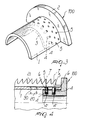
- Figure 1 is a partial perspective view of a flange used in the insulator according to the present invention;
- Figure 2 is a partial schematic view of a composite tube used in the insulator according to the invention;
- Figure 3 is a partial perspective view of a first embodiment of the coupling between the tube and the flange in the insulator according to the invention;
- Figure 4 is a partial sectional view, taken along a longitudinal plane, of a detail of a second embodiment of the coupling between the insulating tube and the flange in the insulator according to the invention.
-
- With reference to the above figures, the hollow insulator according to the present invention comprises an insulating tube 1 made of composite material, preferably fiberglass-reinforced plastic, and at least one metal flange, preferably made of aluminum, which is generally designated by the
reference numeral 100. In particular, as shown in Figures 1 and 3, themetal flange 100 is essentially constituted by two parts: a disc-shaped part 2, which allows the coupling of the insulator to another element, for example another insulator or a frame, and acylindrical part 3, which is conveniently connected to the tube 1. - Advantageously, in the embodiment of the insulator according to the present invention, the connection between the
flange 100 and the tube 1 is provided by means of a plurality of connection means which, by acting substantially under shearing stress, transfer to theflange 100 the flexural stresses due to flexural moments applied to the tube 1. - As shown in detail in Figures 1 and 3, the connection means are constituted by metallic or
composite pins 4 which are fixed to theflange 100 and engage incorresponding holes 5 formed in the surface of the tube 1; in particular, in the illustrated embodiment thepins 4 are constituted by steel cylinders, at least one end portion 4' whereof is threaded, which are screwed inblind seats 6 formed in theflange 100. - In particular, the
pins 4, which protrude from thecylindrical part 3 of the flange, are arranged onsuch part 3 along one or more circumferential rows and theaxis 7 of eachpin 4 is substantially perpendicular to the longitudinal axis 8 of the tube 1. This solution allows thepins 4 to be subjected only to shearing stress and facilitates the operations for mutually fixing theflange 100 and the tube 1. - In a preferred embodiment of the insulator according to the present invention, the
pins 4 are arranged along at least two parallel circumferential rows and, with reference to the longitudinal axis 8 of the tube 1, thepins 4 that belong to one row are staggered with respect to those of the adjacent row. Accordingly, thecorresponding holes 5 formed in the tube 1 that belong to two adjacent rows are also staggered, as shown in Figure 2. This advantageously allows to mutually space the holes and increase the resisting cross-section of the tube 1, thus helping to improve the overall structural strength of the insulator. - Another advantage of the insulator according to the present invention is that the
pins 4 have aheight 20 which is equal to, or in any case smaller than, adistance 30 calculated between the bottom of theseats 6 formed in theflange 100 and the external surface of the insulating tube 1. In this way thepins 4, once fixed, do not protrude from the tube 1 and allow to cover also the tube-flange coupling region withinsulating ribs 21, which are typically made of silicone rubber. This ensures the dual effect of keeping the leakage length of the insulator unchanged and, by means of the sealing of the throughholes 5, of preventing any passage of moisture into the tube 1, which would compromise the dielectric strength of the insulator. - As can be seen in Figures 3 and 4, the flange is connected to the internal surface of the tube.
- In practice it has been observed that the insulator according to the present invention allows to fully achieve the intended aim and objects, since it allows to considerably increase the maximum flexural moment that can be withstood with respect to conventional-type insulators; moreover, experimental tests and numerical analysis have shown that the insulator has a fracture mode which is not brittle but plastic, since between the flexural moment at the elastic limit (first ply failure) and the flexural moment that produces fracture (ultimate laminate failure) there is a significant margin over which the insulating tube retains the loads applied, undergoing great permanent deformations (delamination) but maintaining its structural integrity and thus increasing safety.
- The current insulator thus conceived is susceptible of numerous modifications and variations, all of which are within the scope of the inventive concept; all the details may also be replaced with other technically equivalent elements.
- In practice, the materials used, as well as the dimensions, may be any according to requirements and to the state of the art.
Claims (8)
- Hollow insulator for electric transmission and/or distribution lines, comprising an insulating tube made of composite material which is coupled, at least at an end portion thereof, to a metal flange, characterized in that the coupling between the metal flange and the insulating tube is provided by means of a plurality of connection means adapted to transfer to the flange flexural stresses due to flexural moments applied to the tube, said connection means working substantially under shearing stress.
- Hollow insulator according to claim 1, characterized in that said connection means comprise pins which are fixed to the flange and engage in corresponding holes formed in the tube.
- Hollow insulator according to claim 2, characterized in that said pins are constituted by steel cylinders which are screwed, at least at an end portion, in seats defined in the flange.
- Hollow insulator according to claim 2, characterized in that said pins and said holes are arranged along a circumferential row and have an axis substantially perpendicular to the longitudinal axis of the insulating tube.
- Hollow insulator according to one or more of claims 1 to 3, characterized in that said pins and said holes are arranged along at least two parallel circumferential rows and have an axis which is substantially perpendicular to the longitudinal axis of the insulating tube.
- Hollow insulator according to claim 5, characterized in that the pins and the corresponding holes formed in the insulating tube and belonging to two adjacent parallel circumferential rows are mutually staggered with respect to the longitudinal axis of said tube.
- Hollow insulator according to one or more of the preceding claims, characterized in that said pins are as high as, or lower than, a distance calculated between a bottom of said seats defined in the flange and a outer surface of the insulating tube.
- Hollow insulator according to claim 1, characterized in that said metal flange is made of aluminium and is connected to the internal surface of the tube.
Applications Claiming Priority (2)
| Application Number | Priority Date | Filing Date | Title |
|---|---|---|---|
| IT98MI000751A IT1299049B1 (en) | 1998-04-08 | 1998-04-08 | ISOLATOR ESPECIALLY FOR ELECTRICAL TRANSMISSION AND DISTRIBUTION LINES, HAVING IMPROVED RESISTANCE TO THE |
| ITMI980751 | 1998-04-08 |
Publications (3)
| Publication Number | Publication Date |
|---|---|
| EP0949638A2 true EP0949638A2 (en) | 1999-10-13 |
| EP0949638A3 EP0949638A3 (en) | 2000-11-15 |
| EP0949638B1 EP0949638B1 (en) | 2005-07-20 |
Family
ID=11379707
Family Applications (1)
| Application Number | Title | Priority Date | Filing Date |
|---|---|---|---|
| EP99201049A Expired - Lifetime EP0949638B1 (en) | 1998-04-08 | 1999-04-08 | Insulator for electric transmission and distribution lines, with improved resistance to flexural stresses |
Country Status (8)
| Country | Link |
|---|---|
| US (1) | US6218626B1 (en) |
| EP (1) | EP0949638B1 (en) |
| AT (1) | ATE300090T1 (en) |
| BR (1) | BR9901050A (en) |
| DE (1) | DE69926167T2 (en) |
| IT (1) | IT1299049B1 (en) |
| PL (1) | PL332441A1 (en) |
| ZA (1) | ZA992573B (en) |
Cited By (1)
| Publication number | Priority date | Publication date | Assignee | Title |
|---|---|---|---|---|
| CN102347122A (en) * | 2010-07-23 | 2012-02-08 | 江苏神马电力股份有限公司 | Insulation pipe winding and yarn hanging system |
Families Citing this family (4)
| Publication number | Priority date | Publication date | Assignee | Title |
|---|---|---|---|---|
| JP4376174B2 (en) * | 2004-12-01 | 2009-12-02 | 日本碍子株式会社 | Polymer SP insulator |
| CN103177829A (en) * | 2011-12-20 | 2013-06-26 | 江苏神马电力股份有限公司 | Flange of hollow composite insulator |
| CN105914674B (en) * | 2016-06-07 | 2018-04-03 | 浙江华蕴海洋工程技术服务有限公司 | A kind of cable protection pipe |
| CN113742889B (en) * | 2021-07-29 | 2024-04-02 | 中国南方电网有限责任公司超高压输电公司检修试验中心 | Insulator selecting method |
Citations (2)
| Publication number | Priority date | Publication date | Assignee | Title |
|---|---|---|---|---|
| JPH07245027A (en) * | 1994-03-08 | 1995-09-19 | Hitachi Kasei Mold Kk | Insulating support |
| EP0933787A2 (en) * | 1998-02-03 | 1999-08-04 | Cellpack AG | Column-shaped electrical insulator |
Family Cites Families (5)
| Publication number | Priority date | Publication date | Assignee | Title |
|---|---|---|---|---|
| US1728531A (en) * | 1926-07-28 | 1929-09-17 | Westinghouse Electric & Mfg Co | High-voltage insulator |
| US3213254A (en) * | 1962-12-31 | 1965-10-19 | Westinghouse Electric Corp | Arc resistant orifice embodying fluorocarbon resins and a plastic member |
| DE4421343A1 (en) * | 1994-06-17 | 1995-12-21 | Hoechst Ceram Tec Ag | High voltage ceramic insulator |
| DE19503324A1 (en) * | 1995-02-02 | 1996-08-08 | Hoechst Ceram Tec Ag | Insulator with putty joint and process for its manufacture |
| US5981878A (en) * | 1996-04-22 | 1999-11-09 | Hubbell Incorporated | Polymer insulators with metal caps |
-
1998
- 1998-04-08 IT IT98MI000751A patent/IT1299049B1/en active IP Right Grant
-
1999
- 1999-04-05 US US09/285,756 patent/US6218626B1/en not_active Expired - Fee Related
- 1999-04-07 BR BR9901050-0A patent/BR9901050A/en not_active Application Discontinuation
- 1999-04-07 ZA ZA9902573A patent/ZA992573B/en unknown
- 1999-04-08 PL PL99332441A patent/PL332441A1/en unknown
- 1999-04-08 AT AT99201049T patent/ATE300090T1/en not_active IP Right Cessation
- 1999-04-08 EP EP99201049A patent/EP0949638B1/en not_active Expired - Lifetime
- 1999-04-08 DE DE69926167T patent/DE69926167T2/en not_active Expired - Fee Related
Patent Citations (2)
| Publication number | Priority date | Publication date | Assignee | Title |
|---|---|---|---|---|
| JPH07245027A (en) * | 1994-03-08 | 1995-09-19 | Hitachi Kasei Mold Kk | Insulating support |
| EP0933787A2 (en) * | 1998-02-03 | 1999-08-04 | Cellpack AG | Column-shaped electrical insulator |
Non-Patent Citations (1)
| Title |
|---|
| PATENT ABSTRACTS OF JAPAN vol. 1996, no. 01, 31 January 1996 (1996-01-31) & JP 07 245027 A (HITACHI KASEI MOLD KK;OTHERS: 01), 19 September 1995 (1995-09-19) * |
Cited By (2)
| Publication number | Priority date | Publication date | Assignee | Title |
|---|---|---|---|---|
| CN102347122A (en) * | 2010-07-23 | 2012-02-08 | 江苏神马电力股份有限公司 | Insulation pipe winding and yarn hanging system |
| CN102347122B (en) * | 2010-07-23 | 2013-08-28 | 江苏神马电力股份有限公司 | Insulation pipe winding and yarn hanging system |
Also Published As
| Publication number | Publication date |
|---|---|
| EP0949638A3 (en) | 2000-11-15 |
| EP0949638B1 (en) | 2005-07-20 |
| ZA992573B (en) | 1999-10-07 |
| US6218626B1 (en) | 2001-04-17 |
| BR9901050A (en) | 2000-01-18 |
| IT1299049B1 (en) | 2000-02-07 |
| ATE300090T1 (en) | 2005-08-15 |
| DE69926167D1 (en) | 2005-08-25 |
| ITMI980751A1 (en) | 1999-10-08 |
| DE69926167T2 (en) | 2006-04-27 |
| PL332441A1 (en) | 1999-10-11 |
Similar Documents
| Publication | Publication Date | Title |
|---|---|---|
| US5563379A (en) | Composite electrical insulator | |
| US7180003B2 (en) | Composite insulator | |
| US20180156202A1 (en) | Spar cap assembly for a wind turbine rotor blade | |
| CN103597553B (en) | Reinforced element for the mounting flange of hollow cylindrical insulator shell | |
| KR100375646B1 (en) | Electrical insulator made of silicone rubber for high pressure application | |
| US6218626B1 (en) | Insulator for electric transmission and distribution lines, with improved resistance to flexural stresses | |
| US4057687A (en) | Connection between core and armatures of structures comprising a core of agglomerated fibres | |
| US5986216A (en) | Reinforced insulator | |
| US8420971B2 (en) | Switching chamber insulation arrangement for a circuit breaker | |
| US20170117695A1 (en) | Conductor for Bare Overhead Electric Lines, Especially for Middle-High Thermal Limit, and Low Expansion at High Electronic Loads | |
| US20230378737A1 (en) | Insulating cross arm and preparation method thereof, and transmission pole | |
| US5753864A (en) | Supporting insulator | |
| CN212359302U (en) | Insulating cross arm and power transmission pole | |
| AT506142B1 (en) | ELECTRODE FOR HIGH-RESISTANCE SCHOTT INSULATORS | |
| CN107733119A (en) | A kind of reinforced end ring fixed seat of motor insulating protection | |
| KR20140006533A (en) | Fastening structure of insulator for insulation joint box of ultra high voltage power cable | |
| CN107959266B (en) | Embedded sectional type cable cover | |
| CN215051649U (en) | Integral insulation rail glue joint | |
| CN210349403U (en) | High-elongation high-conductivity overhead conductor | |
| CN209232457U (en) | A kind of compound inslation High-performance cable for construction | |
| CN212182048U (en) | Anti-corona suspension type porcelain insulator | |
| US4529838A (en) | Support bracket for electrical insulator | |
| CN212771905U (en) | Plate type rubber support | |
| CN219458328U (en) | Waterproof insulating partition board and gas-insulated metal-enclosed switchgear | |
| EP3813082B1 (en) | Insulator shed having non-circular tip |
Legal Events
| Date | Code | Title | Description |
|---|---|---|---|
| PUAI | Public reference made under article 153(3) epc to a published international application that has entered the european phase |
Free format text: ORIGINAL CODE: 0009012 |
|
| AK | Designated contracting states |
Kind code of ref document: A2 Designated state(s): AT BE CH DE DK ES FI FR IT LI NL SE |
|
| AX | Request for extension of the european patent |
Free format text: AL;LT;LV;MK;RO;SI |
|
| PUAL | Search report despatched |
Free format text: ORIGINAL CODE: 0009013 |
|
| AK | Designated contracting states |
Kind code of ref document: A3 Designated state(s): AT BE CH CY DE DK ES FI FR GB GR IE IT LI LU MC NL PT SE |
|
| AX | Request for extension of the european patent |
Free format text: AL;LT;LV;MK;RO;SI |
|
| 17P | Request for examination filed |
Effective date: 20010507 |
|
| AKX | Designation fees paid |
Free format text: AT BE CH DE DK ES FI FR IT LI NL SE |
|
| 17Q | First examination report despatched |
Effective date: 20040322 |
|
| GRAP | Despatch of communication of intention to grant a patent |
Free format text: ORIGINAL CODE: EPIDOSNIGR1 |
|
| GRAS | Grant fee paid |
Free format text: ORIGINAL CODE: EPIDOSNIGR3 |
|
| GRAA | (expected) grant |
Free format text: ORIGINAL CODE: 0009210 |
|
| AK | Designated contracting states |
Kind code of ref document: B1 Designated state(s): AT BE CH DE DK ES FI FR IT LI NL SE |
|
| PG25 | Lapsed in a contracting state [announced via postgrant information from national office to epo] |
Ref country code: NL Free format text: LAPSE BECAUSE OF FAILURE TO SUBMIT A TRANSLATION OF THE DESCRIPTION OR TO PAY THE FEE WITHIN THE PRESCRIBED TIME-LIMIT Effective date: 20050720 Ref country code: FI Free format text: LAPSE BECAUSE OF FAILURE TO SUBMIT A TRANSLATION OF THE DESCRIPTION OR TO PAY THE FEE WITHIN THE PRESCRIBED TIME-LIMIT Effective date: 20050720 Ref country code: BE Free format text: LAPSE BECAUSE OF FAILURE TO SUBMIT A TRANSLATION OF THE DESCRIPTION OR TO PAY THE FEE WITHIN THE PRESCRIBED TIME-LIMIT Effective date: 20050720 Ref country code: AT Free format text: LAPSE BECAUSE OF FAILURE TO SUBMIT A TRANSLATION OF THE DESCRIPTION OR TO PAY THE FEE WITHIN THE PRESCRIBED TIME-LIMIT Effective date: 20050720 |
|
| REG | Reference to a national code |
Ref country code: CH Ref legal event code: EP |
|
| REG | Reference to a national code |
Ref country code: CH Ref legal event code: NV Representative=s name: ISLER & PEDRAZZINI AG |
|
| REF | Corresponds to: |
Ref document number: 69926167 Country of ref document: DE Date of ref document: 20050825 Kind code of ref document: P |
|
| PG25 | Lapsed in a contracting state [announced via postgrant information from national office to epo] |
Ref country code: SE Free format text: LAPSE BECAUSE OF FAILURE TO SUBMIT A TRANSLATION OF THE DESCRIPTION OR TO PAY THE FEE WITHIN THE PRESCRIBED TIME-LIMIT Effective date: 20051020 Ref country code: DK Free format text: LAPSE BECAUSE OF FAILURE TO SUBMIT A TRANSLATION OF THE DESCRIPTION OR TO PAY THE FEE WITHIN THE PRESCRIBED TIME-LIMIT Effective date: 20051020 |
|
| PG25 | Lapsed in a contracting state [announced via postgrant information from national office to epo] |
Ref country code: ES Free format text: LAPSE BECAUSE OF FAILURE TO SUBMIT A TRANSLATION OF THE DESCRIPTION OR TO PAY THE FEE WITHIN THE PRESCRIBED TIME-LIMIT Effective date: 20051031 |
|
| NLV1 | Nl: lapsed or annulled due to failure to fulfill the requirements of art. 29p and 29m of the patents act | ||
| ET | Fr: translation filed | ||
| PLBE | No opposition filed within time limit |
Free format text: ORIGINAL CODE: 0009261 |
|
| STAA | Information on the status of an ep patent application or granted ep patent |
Free format text: STATUS: NO OPPOSITION FILED WITHIN TIME LIMIT |
|
| 26N | No opposition filed |
Effective date: 20060421 |
|
| REG | Reference to a national code |
Ref country code: CH Ref legal event code: PCAR Free format text: ISLER & PEDRAZZINI AG;POSTFACH 1772;8027 ZUERICH (CH) |
|
| PGFP | Annual fee paid to national office [announced via postgrant information from national office to epo] |
Ref country code: IT Payment date: 20090427 Year of fee payment: 11 Ref country code: FR Payment date: 20090414 Year of fee payment: 11 Ref country code: DE Payment date: 20090422 Year of fee payment: 11 |
|
| PGFP | Annual fee paid to national office [announced via postgrant information from national office to epo] |
Ref country code: CH Payment date: 20090417 Year of fee payment: 11 |
|
| REG | Reference to a national code |
Ref country code: CH Ref legal event code: PL |
|
| REG | Reference to a national code |
Ref country code: FR Ref legal event code: ST Effective date: 20101230 |
|
| PG25 | Lapsed in a contracting state [announced via postgrant information from national office to epo] |
Ref country code: LI Free format text: LAPSE BECAUSE OF NON-PAYMENT OF DUE FEES Effective date: 20100430 Ref country code: DE Free format text: LAPSE BECAUSE OF NON-PAYMENT OF DUE FEES Effective date: 20101103 Ref country code: CH Free format text: LAPSE BECAUSE OF NON-PAYMENT OF DUE FEES Effective date: 20100430 |
|
| PG25 | Lapsed in a contracting state [announced via postgrant information from national office to epo] |
Ref country code: IT Free format text: LAPSE BECAUSE OF NON-PAYMENT OF DUE FEES Effective date: 20100408 |
|
| PG25 | Lapsed in a contracting state [announced via postgrant information from national office to epo] |
Ref country code: FR Free format text: LAPSE BECAUSE OF NON-PAYMENT OF DUE FEES Effective date: 20100430 |