EP0948740B1 - Method for producing compacted cast iron - Google Patents
Method for producing compacted cast iron Download PDFInfo
- Publication number
- EP0948740B1 EP0948740B1 EP97914689A EP97914689A EP0948740B1 EP 0948740 B1 EP0948740 B1 EP 0948740B1 EP 97914689 A EP97914689 A EP 97914689A EP 97914689 A EP97914689 A EP 97914689A EP 0948740 B1 EP0948740 B1 EP 0948740B1
- Authority
- EP
- European Patent Office
- Prior art keywords
- melt
- responsive means
- coating
- cast iron
- wall
- Prior art date
- Legal status (The legal status is an assumption and is not a legal conclusion. Google has not performed a legal analysis and makes no representation as to the accuracy of the status listed.)
- Expired - Lifetime
Links
Images

Classifications
-
- G—PHYSICS
- G01—MEASURING; TESTING
- G01N—INVESTIGATING OR ANALYSING MATERIALS BY DETERMINING THEIR CHEMICAL OR PHYSICAL PROPERTIES
- G01N25/00—Investigating or analyzing materials by the use of thermal means
- G01N25/02—Investigating or analyzing materials by the use of thermal means by investigating changes of state or changes of phase; by investigating sintering
- G01N25/04—Investigating or analyzing materials by the use of thermal means by investigating changes of state or changes of phase; by investigating sintering of melting point; of freezing point; of softening point
- G01N25/06—Analysis by measuring change of freezing point
-
- B—PERFORMING OPERATIONS; TRANSPORTING
- B22—CASTING; POWDER METALLURGY
- B22D—CASTING OF METALS; CASTING OF OTHER SUBSTANCES BY THE SAME PROCESSES OR DEVICES
- B22D2/00—Arrangement of indicating or measuring devices, e.g. for temperature or viscosity of the fused mass
-
- B—PERFORMING OPERATIONS; TRANSPORTING
- B22—CASTING; POWDER METALLURGY
- B22D—CASTING OF METALS; CASTING OF OTHER SUBSTANCES BY THE SAME PROCESSES OR DEVICES
- B22D2/00—Arrangement of indicating or measuring devices, e.g. for temperature or viscosity of the fused mass
- B22D2/006—Arrangement of indicating or measuring devices, e.g. for temperature or viscosity of the fused mass for the temperature of the molten metal
-
- C—CHEMISTRY; METALLURGY
- C21—METALLURGY OF IRON
- C21C—PROCESSING OF PIG-IRON, e.g. REFINING, MANUFACTURE OF WROUGHT-IRON OR STEEL; TREATMENT IN MOLTEN STATE OF FERROUS ALLOYS
- C21C1/00—Refining of pig-iron; Cast iron
- C21C1/10—Making spheroidal graphite cast-iron
-
- C—CHEMISTRY; METALLURGY
- C22—METALLURGY; FERROUS OR NON-FERROUS ALLOYS; TREATMENT OF ALLOYS OR NON-FERROUS METALS
- C22C—ALLOYS
- C22C38/00—Ferrous alloys, e.g. steel alloys
- C22C38/02—Ferrous alloys, e.g. steel alloys containing silicon
-
- C—CHEMISTRY; METALLURGY
- C22—METALLURGY; FERROUS OR NON-FERROUS ALLOYS; TREATMENT OF ALLOYS OR NON-FERROUS METALS
- C22C—ALLOYS
- C22C38/00—Ferrous alloys, e.g. steel alloys
- C22C38/04—Ferrous alloys, e.g. steel alloys containing manganese
-
- G—PHYSICS
- G01—MEASURING; TESTING
- G01N—INVESTIGATING OR ANALYSING MATERIALS BY DETERMINING THEIR CHEMICAL OR PHYSICAL PROPERTIES
- G01N25/00—Investigating or analyzing materials by the use of thermal means
- G01N25/02—Investigating or analyzing materials by the use of thermal means by investigating changes of state or changes of phase; by investigating sintering
- G01N25/04—Investigating or analyzing materials by the use of thermal means by investigating changes of state or changes of phase; by investigating sintering of melting point; of freezing point; of softening point
-
- G—PHYSICS
- G01—MEASURING; TESTING
- G01N—INVESTIGATING OR ANALYSING MATERIALS BY DETERMINING THEIR CHEMICAL OR PHYSICAL PROPERTIES
- G01N33/00—Investigating or analysing materials by specific methods not covered by groups G01N1/00 - G01N31/00
- G01N33/20—Metals
- G01N33/205—Metals in liquid state, e.g. molten metals
Definitions
- one way of carrying out such determinations is to perform a thermal analysis of the melt.
- a small sample of the molten metal alloy is taken and is allowed to solidify. During this process, the temperature is measured as a function of time.
- the configuration is then determined by comparing the obtained cooling curve and its time derivative with reference curves.
- thermal analysis methods are disclosed in e.g. WO86/01755, WO91/13176 and WO92/06809.
- a sample of molten metal is obtained by immersing a sample vessel into the molten iron, whereafter said sample is allowed to solidify.
- the thermal analysis is performed by using temperature responsive means, normally two thermocouples. One of said means is positioned in the centre of the vessel and the other near the vessel wall.
- a sample vessel where the inner surface is coated with a reactive wall is used.
- the reactive coating comprising oxides of silicon, manganese, iron and/or sodium, reacts with active magnesium in the sampled iron and lowers the level of active magnesium in the wall region of the sample vessel.
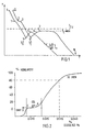
- Fig. 1 discloses typical cooling curves that can be obtained by using the method according to WO86/01755;
- Fig. 2 illustrates a diagram showing the nodularity percentage as a function of the magnesium percentage.
- 0 % nodularity corresponds to a complete compacted graphite cast iron (CGI)
- 100 % corresponds to a complete spheroidal graphite iron (SGI)
- values below 0 % nodularity relate to grey cast iron.
- 0 % nodularity corresponds to 100 % compacted graphite cast iron and the bottom of this axis corresponds to 100 % flaky grey cast iron;
- Fig. 3 presents cooling curves obtained by the present invention.
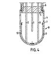
- Fig. 4 discloses an example of a sample vessel equipped with three thermocouples that can be used in the method according to the present invention.
- thermocouples one arranged in the centre of the sample vessel and the other near the vessel wall. These two thermocouples provide two distictly different cooling curves which are illustrated in Fig. 1.
- Fig. 2 shows the amount of spheroidal graphite iron (SGI) and grey cast iron, respectively, as a function of the magnesium level (structural modifyer).
- Figure 3 illustrates an example of three cooling curves measured simultaneously under controlled conditions, from the same sample of molten compacted graphite iron (CGI) with and without wall reaction.
- CGI molten compacted graphite iron
- FIG 3 clearly shows a normal centre thermocouple cooling curve and two different wall cooling curves.
- the wall thermocouple adjacent to the 3% sulfur coating has a typically obvious wall reaction initiating at the point A (approx. 60 seconds, 1143°C) and continuing to point B (approx. 100 seconds, 1144°C).
- point A approximately 60 seconds
- point B approximately 100 seconds
- 1144°C approximately 100 seconds
- the ultimate result of this "shift" in the curve is that the minimum temperature on the wall curve is approximately 2.5°C higher in the presence of a wall reaction. This is extremely important from a production point-of-view since a difference of 2.5°C in measured undercooling can correspond to the need for +/- 0.5 kg inoculant per tonne to avoid either excessive nodularity (-0.5 kg/tonne) or carbide formation (+0.5 kg/tonne) according to WO86/01755.
- thermoresponsive means in the above mentioned manner provides an unforeseen advantage.
- the present invention allows two distinctly different types of information to be collected.
- WO 86/01755 teaches the importance of simultaneously controlling the magnesium and inoculant content of the molten iron to remain within the CGI specification window.
- the present invention not only allows accurate measurement of both values (inoculant efficiency and proximity to grey iron) but it also allows for the coating to be extremely reactive (containing sulfur rather than reducible oxides as in WO 92/06809) without compromizing the ability to measure the inoculating efficiency.
- Fig. 4 discloses a sample vessel that can be used in the method according to the invention.
- the inner wall of a crucible (8) is partially coated with
- thermocouples (1,2,3) arranged in such a way that one (1) is situated in the centre of the crucible (8), one (2) close to the reactive coating (2) and the last one (3) close to the relatively inert coating (9), are fixed in a ceramic plug (5) and contained inside a cardboard tube (6).
Abstract
Description
- In the foundry industry it is often desirable to be able to determine in which configuration a certain molten cast iron will solidify. one way of carrying out such determinations is to perform a thermal analysis of the melt. A small sample of the molten metal alloy is taken and is allowed to solidify. During this process, the temperature is measured as a function of time. The configuration is then determined by comparing the obtained cooling curve and its time derivative with reference curves. Such thermal analysis methods are disclosed in e.g. WO86/01755, WO91/13176 and WO92/06809.
- In the above mentioned methods, a sample of molten metal is obtained by immersing a sample vessel into the molten iron, whereafter said sample is allowed to solidify. The thermal analysis is performed by using temperature responsive means, normally two thermocouples. One of said means is positioned in the centre of the vessel and the other near the vessel wall.
- In the method according to WO92/06809 a sample vessel where the inner surface is coated with a reactive wall is used. The reactive coating, comprising oxides of silicon, manganese, iron and/or sodium, reacts with active magnesium in the sampled iron and lowers the level of active magnesium in the wall region of the sample vessel.
- By using a coated sample vessel according to WO92/06809 it is possible to perform more accurate predictions of solidification structure compared to the state of the art as represented by WO86/01755. In particular, the consumption of magnesium in the near-wall region simulates the natural fading of magnesium during the casting period and provides a predictive warning of magnesium loss. While this feature is indespensible for the reliable production of compacted graphite iron, it is of great importance to be able to increase the accuracy further.
- Now it has turned out that by carrying out a method according to claim 1, it is possible to further increase the accuracy of the solidification structure predictions of the molten cast iron.
- The present invention will be explained in more detail with reference to the figures, in which
- Fig. 1 discloses typical cooling curves that can be obtained by using the method according to WO86/01755;
- Fig. 2 illustrates a diagram showing the nodularity percentage as a function of the magnesium percentage. In this diagram 0 % nodularity corresponds to a complete compacted graphite cast iron (CGI), whereas 100 % corresponds to a complete spheroidal graphite iron (SGI); Finally, values below 0 % nodularity relate to grey cast iron. Actually, 0 % nodularity corresponds to 100 % compacted graphite cast iron and the bottom of this axis corresponds to 100 % flaky grey cast iron;
- Fig. 3 presents cooling curves obtained by the present invention; and
- Fig. 4 discloses an example of a sample vessel equipped with three thermocouples that can be used in the method according to the present invention.
- As previosly mentioned, the procedure for predicting in which configuration a molten cast iron will solidify according to WO86/01755 makes use of two thermocouples, one arranged in the centre of the sample vessel and the other near the vessel wall. These two thermocouples provide two distictly different cooling curves which are illustrated in Fig. 1.
- The description of key points on these curves is properly made in WO86/01755. A second consideration to be made during the interpretation of the cooling curves is taught in WO92/0-6809. In this case, a reactive coating on the sample wall consumes magnesium from the melt and causes the near-wall region to solidify as grey iron. The latent heat liberated by the precipitation and growth of grey iron graphite flakes cause a "deflection" in the normal wall cooling curve. The grey iron/compacted graphite iron (CGI) transition and the "deflected" wall curve are illustrated in Fig. 2 and 3 respectively.
- As already mentioned Fig. 2 shows the amount of spheroidal graphite iron (SGI) and grey cast iron, respectively, as a function of the magnesium level (structural modifyer). If the melt composition is at point A, the wall reduction of 0.003% Mg as taught in WO92/06809 results in the near-wall melt attaining composition B which is still in the CGI plateau and therefore there is no deflection in the wall curve (as in Fig. 1). However, if the initial melt composition is at point C, the same wall reduction of 0.003% Mg results in the formation of flake iron (Point D) in the near-wall region.
- It has turned out that all the measurement points referred to in WO86/0175 and WO92/06809 are essential information points. One of the data points referred to in WO86/01755 is the minimum temperature on the wall curve prior to eutectic recalescence, so-called Tv. However, in the presence of a wall reaction due to flake graphite formation, the minimum temperature on the wall curve is altered or "masked" by the latent heat liberated during flake formation.
- Figure 3 illustrates an example of three cooling curves measured simultaneously under controlled conditions, from the same sample of molten compacted graphite iron (CGI) with and without wall reaction. In order to ensure a wall reaction as described in WO92/06809, one sample cup was coated with a 3% sulfur solution while the other sample cup was coated with a less reactive coating. The three cooling curves are described in more detail, according to labelling on Fig. 4b, as follows:
- Ta 3%
- Centre thermocouple from sample cup containing 3% sulfur wall coating.
-
Tb 3% - Wall thermocouple from sample cup containing 3 % sulfur wall coating.
- Tb 1%
- Wall thermocouple from sample cup containing 1 % sulfur wall coating.
- Figure 3 clearly shows a normal centre thermocouple cooling curve and two different wall cooling curves. The wall thermocouple adjacent to the 3% sulfur coating has a typically obvious wall reaction initiating at the point A (approx. 60 seconds, 1143°C) and continuing to point B (approx. 100 seconds, 1144°C). The ultimate result of this "shift" in the curve is that the minimum temperature on the wall curve is approximately 2.5°C higher in the presence of a wall reaction. This is extremely important from a production point-of-view since a difference of 2.5°C in measured undercooling can correspond to the need for +/- 0.5 kg inoculant per tonne to avoid either excessive nodularity (-0.5 kg/tonne) or carbide formation (+0.5 kg/tonne) according to WO86/01755.
- The use of three thermoresponsive means in the above mentioned manner provides an unforeseen advantage. Firstly, the present invention allows two distinctly different types of information to be collected. WO 86/01755 teaches the importance of simultaneously controlling the magnesium and inoculant content of the molten iron to remain within the CGI specification window. The present invention not only allows accurate measurement of both values (inoculant efficiency and proximity to grey iron) but it also allows for the coating to be extremely reactive (containing sulfur rather than reducible oxides as in WO 92/06809) without compromizing the ability to measure the inoculating efficiency. This, for example, when casting components with a long pouring (small castings) or a long solidification time (large castings) allows a highly reactive coating to be used to simulate the Mg-fading, which was previously not possible in the method according to WO 92/06809 due to the adverse affect on the measurement of nucleating potential.
- Fig. 4 discloses a sample vessel that can be used in the method according to the invention. The inner wall of a crucible (8) is partially coated with
- I
- a reactive coating (10) containing 0 - 5% sulfur, 0 - 10% of oxides of silicon, manganese or iron, or 0 - 0.5% of oxides of potassium and sodium; and
- II
- an relatively inert coating (9) such as aluminium or zirconium oxide.
- Three thermocouples (1,2,3) arranged in such a way that one (1) is situated in the centre of the crucible (8), one (2) close to the reactive coating (2) and the last one (3) close to the relatively inert coating (9), are fixed in a ceramic plug (5) and contained inside a cardboard tube (6).
Claims (5)
- A method relating to the production of cast iron castings of the kind which contain graphite crystals in compacted form and entailing controlling and correcting the composition of a cast iron melt, the method comprising preparing a cast iron melt and adding to the melt a structure-modifying agent and nucleating agent in amounts according to experience just enough to give fully compacted graphite iron when solidified directly, wherein a sample of melt is extracted in a sample vessel where the inner wall is partially coated with a material which will lower the concentration of dissolved elementary magnesium by at least 0.003% or a corresponding percentage of some other modifying agent in the melt in the vicinity of that wall, recording temperatures registrated by temperature responsive means, at least one of which is arranged in the centre of the vessel, and at least one of which is placed close to the coating affecting the level of dissolved elementary magnesium, and letting said thermal responsive means reach thermal equilibrium with the melt, evaluating from the so recorded cooling in a manner known per se the characteristics of the melt, and correcting the nucleating agent and magnesium content or the content of said other modifying agent so that compacted graphite crystals are formed during all the pouring and solidification time that is needed in a foundry process, characterised in that at least one further temperature responsive means and optionally one further inertly coated sample vessel are used, said further temperature responsive means being situated close to an inert coating in said sample vessel or said further inertly coated sample vessel, wherein said inert coating does not affect the level of dissolved elementary magnesium in the melt.
- A method according to claim 1, characterised in that the coating affecting the level of dissolved elementary magnesium comprises 0-5 % sulfur, 0-10% oxides of silicon, manganese or iron and/or 0-0.5% oxides of potassium and sodium.
- A method according to claim 2, characterised in that the coating affecting the level of dissolved elementary magnesium comprises 3-5 % sulfur.
- A method according to anyone of the proceeding claims, characterised in that the temperature responsive means are thermocouples.
- A method according to anyone of claims 1-4, characterised in that the temperature responsive means are means for carrying out pyrometrical measurements.
Applications Claiming Priority (3)
| Application Number | Priority Date | Filing Date | Title |
|---|---|---|---|
| SE9601026A SE506802C2 (en) | 1996-03-18 | 1996-03-18 | Process for producing compact graphite iron comprising a thermal analysis step |
| SE9601026 | 1996-03-18 | ||
| PCT/SE1997/000350 WO1997035184A1 (en) | 1996-03-18 | 1997-02-28 | New method |
Publications (2)
| Publication Number | Publication Date |
|---|---|
| EP0948740A1 EP0948740A1 (en) | 1999-10-13 |
| EP0948740B1 true EP0948740B1 (en) | 2003-08-06 |
Family
ID=20401831
Family Applications (1)
| Application Number | Title | Priority Date | Filing Date |
|---|---|---|---|
| EP97914689A Expired - Lifetime EP0948740B1 (en) | 1996-03-18 | 1997-02-28 | Method for producing compacted cast iron |
Country Status (10)
| Country | Link |
|---|---|
| US (1) | US6102981A (en) |
| EP (1) | EP0948740B1 (en) |
| JP (1) | JP4014636B2 (en) |
| KR (1) | KR20000064668A (en) |
| AU (1) | AU2183997A (en) |
| DE (1) | DE69724004T2 (en) |
| ID (1) | ID16247A (en) |
| SE (1) | SE506802C2 (en) |
| WO (1) | WO1997035184A1 (en) |
| ZA (1) | ZA972061B (en) |
Families Citing this family (10)
| Publication number | Priority date | Publication date | Assignee | Title |
|---|---|---|---|---|
| SE9704208L (en) * | 1997-11-17 | 1999-05-18 | Sintercast Ab | New procedure |
| SE511655C2 (en) * | 1998-02-26 | 1999-11-01 | Novacast Ab | Device and method for thermal analysis of metal melts |
| SE9802690D0 (en) * | 1998-08-07 | 1998-08-07 | Astra Ab | Mixing apparatus |
| SE515026C2 (en) * | 1998-12-18 | 2001-05-28 | Sintercast Ab | Process for predicting the microstructure of cast iron, device and computer software product for carrying out the method |
| SE0104252D0 (en) * | 2001-12-17 | 2001-12-17 | Sintercast Ab | New device |
| SE534912C2 (en) | 2010-06-16 | 2012-02-14 | Scania Cv Ab | Method for determining the amount of inoculant to be added to a cast iron melt |
| SE537286C2 (en) * | 2013-07-12 | 2015-03-24 | Sintercast Ab | Composition for coating a surface, coating, sampling device for thermal analysis of solidifying metal co-production of sampling device |
| SE537282C2 (en) | 2013-07-12 | 2015-03-24 | Sintercast Ab | A sampling device for thermal analysis |
| EP3356782A1 (en) * | 2015-09-29 | 2018-08-08 | Tekniska Högskolan I Jönköping Aktiebolag | Sampling device and method for sampling a liquid or viscous material |
| RU2654822C1 (en) * | 2017-06-02 | 2018-05-22 | Антон Владимирович Шмаков | Device for determination of thermal parameters of phase transformation |
Family Cites Families (4)
| Publication number | Priority date | Publication date | Assignee | Title |
|---|---|---|---|---|
| SE466059B (en) * | 1990-02-26 | 1991-12-09 | Sintercast Ltd | PROCEDURES FOR CONTROL AND ADJUSTMENT OF PRIMARY NUCLEAR FORM |
| SE501003C2 (en) * | 1990-10-15 | 1994-10-17 | Sintercast Ab | Process for the production of iron |
| SE469712B (en) * | 1990-10-15 | 1993-08-30 | Sintercast Ltd | PROCEDURES FOR PREPARING THE IRON WITH COMPACT GRAPHITE |
| SE9500297D0 (en) * | 1995-01-27 | 1995-01-27 | Sintercast Ab | A sampling device for thermal analysis |
-
1996
- 1996-03-18 SE SE9601026A patent/SE506802C2/en not_active IP Right Cessation
-
1997
- 1997-02-28 DE DE69724004T patent/DE69724004T2/en not_active Expired - Fee Related
- 1997-02-28 JP JP53339297A patent/JP4014636B2/en not_active Expired - Fee Related
- 1997-02-28 AU AU21839/97A patent/AU2183997A/en not_active Abandoned
- 1997-02-28 US US09/155,016 patent/US6102981A/en not_active Expired - Fee Related
- 1997-02-28 WO PCT/SE1997/000350 patent/WO1997035184A1/en active IP Right Grant
- 1997-02-28 KR KR1019980707384A patent/KR20000064668A/en not_active Application Discontinuation
- 1997-02-28 EP EP97914689A patent/EP0948740B1/en not_active Expired - Lifetime
- 1997-03-10 ZA ZA9702061A patent/ZA972061B/en unknown
- 1997-03-17 ID IDP970850A patent/ID16247A/en unknown
Also Published As
| Publication number | Publication date |
|---|---|
| SE9601026L (en) | 1997-09-19 |
| SE9601026D0 (en) | 1996-03-18 |
| DE69724004T2 (en) | 2004-06-09 |
| ID16247A (en) | 1997-09-11 |
| AU2183997A (en) | 1997-10-10 |
| DE69724004D1 (en) | 2003-09-11 |
| EP0948740A1 (en) | 1999-10-13 |
| SE506802C2 (en) | 1998-02-16 |
| US6102981A (en) | 2000-08-15 |
| WO1997035184A1 (en) | 1997-09-25 |
| KR20000064668A (en) | 2000-11-06 |
| ZA972061B (en) | 1997-09-17 |
| JP4014636B2 (en) | 2007-11-28 |
| JP2000508061A (en) | 2000-06-27 |
Similar Documents
| Publication | Publication Date | Title |
|---|---|---|
| US4667725A (en) | Method for producing cast-iron, and in particular cast-iron which contains vermicular graphite | |
| EP0553188B1 (en) | A method for the production of compacted graphite cast iron | |
| JP2510947B2 (en) | Method for discriminating presence / absence of spheroidizing agent or CV agent in molten cast iron and chilling tendency of flake graphite cast iron, and sampling container used therefor | |
| EP0948740B1 (en) | Method for producing compacted cast iron | |
| KR100218122B1 (en) | Method for the production of ductile cast iron | |
| US6571856B1 (en) | Method for predicting the microstructure of solidifying cast iron | |
| US5577545A (en) | Determination of the carbon equivalent in structure-modified cast iron | |
| KR100646310B1 (en) | Method for producing compacted graphite cast iron castings or spheroidal graphite cast iron castings and apparatus used therefor | |
| KR100493178B1 (en) | Method for judging the properties of molten cast iron | |
| US5305815A (en) | Method and apparatus for predicting microstructure of cast iron |
Legal Events
| Date | Code | Title | Description |
|---|---|---|---|
| PUAI | Public reference made under article 153(3) epc to a published international application that has entered the european phase |
Free format text: ORIGINAL CODE: 0009012 |
|
| 17P | Request for examination filed |
Effective date: 19980717 |
|
| AK | Designated contracting states |
Kind code of ref document: A1 Designated state(s): DE SE |
|
| 17Q | First examination report despatched |
Effective date: 20020626 |
|
| RTI1 | Title (correction) |
Free format text: METHOD FOR PRODUCING COMPACTED CAST IRON |
|
| GRAH | Despatch of communication of intention to grant a patent |
Free format text: ORIGINAL CODE: EPIDOS IGRA |
|
| GRAH | Despatch of communication of intention to grant a patent |
Free format text: ORIGINAL CODE: EPIDOS IGRA |
|
| GRAA | (expected) grant |
Free format text: ORIGINAL CODE: 0009210 |
|
| AK | Designated contracting states |
Designated state(s): DE SE |
|
| REF | Corresponds to: |
Ref document number: 69724004 Country of ref document: DE Date of ref document: 20030911 Kind code of ref document: P |
|
| REG | Reference to a national code |
Ref country code: SE Ref legal event code: TRGR |
|
| PLBE | No opposition filed within time limit |
Free format text: ORIGINAL CODE: 0009261 |
|
| STAA | Information on the status of an ep patent application or granted ep patent |
Free format text: STATUS: NO OPPOSITION FILED WITHIN TIME LIMIT |
|
| 26N | No opposition filed |
Effective date: 20040507 |
|
| PG25 | Lapsed in a contracting state [announced via postgrant information from national office to epo] |
Ref country code: DE Free format text: LAPSE BECAUSE OF NON-PAYMENT OF DUE FEES Effective date: 20040901 |
|
| PGFP | Annual fee paid to national office [announced via postgrant information from national office to epo] |
Ref country code: SE Payment date: 20070221 Year of fee payment: 11 |
|
| EUG | Se: european patent has lapsed | ||
| PG25 | Lapsed in a contracting state [announced via postgrant information from national office to epo] |
Ref country code: SE Free format text: LAPSE BECAUSE OF NON-PAYMENT OF DUE FEES Effective date: 20080301 |