EP0948727B1 - A refrigeration system using a slurry of solid particles in a liquid - Google Patents
A refrigeration system using a slurry of solid particles in a liquid Download PDFInfo
- Publication number
- EP0948727B1 EP0948727B1 EP97913622A EP97913622A EP0948727B1 EP 0948727 B1 EP0948727 B1 EP 0948727B1 EP 97913622 A EP97913622 A EP 97913622A EP 97913622 A EP97913622 A EP 97913622A EP 0948727 B1 EP0948727 B1 EP 0948727B1
- Authority
- EP
- European Patent Office
- Prior art keywords
- mixing tank
- refrigeration system
- inlet
- outlet
- carbon dioxide
- Prior art date
- Legal status (The legal status is an assumption and is not a legal conclusion. Google has not performed a legal analysis and makes no representation as to the accuracy of the status listed.)
- Expired - Lifetime
Links
Images

Classifications
-
- F—MECHANICAL ENGINEERING; LIGHTING; HEATING; WEAPONS; BLASTING
- F25—REFRIGERATION OR COOLING; COMBINED HEATING AND REFRIGERATION SYSTEMS; HEAT PUMP SYSTEMS; MANUFACTURE OR STORAGE OF ICE; LIQUEFACTION SOLIDIFICATION OF GASES
- F25D—REFRIGERATORS; COLD ROOMS; ICE-BOXES; COOLING OR FREEZING APPARATUS NOT OTHERWISE PROVIDED FOR
- F25D16/00—Devices using a combination of a cooling mode associated with refrigerating machinery with a cooling mode not associated with refrigerating machinery
-
- F—MECHANICAL ENGINEERING; LIGHTING; HEATING; WEAPONS; BLASTING
- F25—REFRIGERATION OR COOLING; COMBINED HEATING AND REFRIGERATION SYSTEMS; HEAT PUMP SYSTEMS; MANUFACTURE OR STORAGE OF ICE; LIQUEFACTION SOLIDIFICATION OF GASES
- F25D—REFRIGERATORS; COLD ROOMS; ICE-BOXES; COOLING OR FREEZING APPARATUS NOT OTHERWISE PROVIDED FOR
- F25D17/00—Arrangements for circulating cooling fluids; Arrangements for circulating gas, e.g. air, within refrigerated spaces
- F25D17/02—Arrangements for circulating cooling fluids; Arrangements for circulating gas, e.g. air, within refrigerated spaces for circulating liquids, e.g. brine
-
- F—MECHANICAL ENGINEERING; LIGHTING; HEATING; WEAPONS; BLASTING
- F25—REFRIGERATION OR COOLING; COMBINED HEATING AND REFRIGERATION SYSTEMS; HEAT PUMP SYSTEMS; MANUFACTURE OR STORAGE OF ICE; LIQUEFACTION SOLIDIFICATION OF GASES
- F25B—REFRIGERATION MACHINES, PLANTS OR SYSTEMS; COMBINED HEATING AND REFRIGERATION SYSTEMS; HEAT PUMP SYSTEMS
- F25B2309/00—Gas cycle refrigeration machines
- F25B2309/06—Compression machines, plants or systems characterised by the refrigerant being carbon dioxide
-
- F—MECHANICAL ENGINEERING; LIGHTING; HEATING; WEAPONS; BLASTING
- F25—REFRIGERATION OR COOLING; COMBINED HEATING AND REFRIGERATION SYSTEMS; HEAT PUMP SYSTEMS; MANUFACTURE OR STORAGE OF ICE; LIQUEFACTION SOLIDIFICATION OF GASES
- F25B—REFRIGERATION MACHINES, PLANTS OR SYSTEMS; COMBINED HEATING AND REFRIGERATION SYSTEMS; HEAT PUMP SYSTEMS
- F25B9/00—Compression machines, plants or systems, in which the refrigerant is air or other gas of low boiling point
- F25B9/002—Compression machines, plants or systems, in which the refrigerant is air or other gas of low boiling point characterised by the refrigerant
- F25B9/008—Compression machines, plants or systems, in which the refrigerant is air or other gas of low boiling point characterised by the refrigerant the refrigerant being carbon dioxide
Definitions
- the present invention relates to a refrigeration system using a slurry of solid particles in a liquid as a cooling medium.
- the particles should be substantially immiscible in the liquid and sublimate at the temperatures and pressures used in a sublimator (evaporator) of the refrigeration system.
- DE-A-30 04 114 describes a refrigeration system using particles of solid carbon dioxide and terpene as transport liquid. More particularly, liquid carbon dioxide (carbonic acid anhydride) is expanded below the triple point such that it converts to carbon dioxide particles (snow) and vapor. The carbon dioxide particles are mixed with terpene and the resulting slurry is pumped through a sublimator (evaporator) where the carbon dioxide particles are sublimated at least partly, thereby cooling the sublimator (evaporator) which may be used for the cooling of air, e.g. for freezing and storing of food at so low temperatures as from about -60°C to about -80°C.
- a sublimator evaporator
- the effluent from the evaporator/sublimator containing terpene, carbon dioxide vapor and remaining carbon dioxide particles, is separated such that the carbon dioxide vapor may be sucked into a compressor and converted to liquid state in a condenser.
- the liquid carbon dioxide may thereafter be returned into the mixing-tank for a new cooling cycle.
- a main object of the present invention is to improve the operational reliability of the prior art sublimation system.
- An other object of the present invention is to increase the efficiency of such an improved system.
- a refrigeration system which comprises
- a pump may be inserted into the first conduit for pumping the slurry from the mixing tank to and through the sublimator.
- the refrigeration system according to the invention also has no descending parts in the conduit leading from the pump to the sublimator and no descending paths within the sublimator, thereby eliminating clogging of the solid particles from the outlet of the pump to the outlet of the sublimator.
- the mixing tank has an inlet connected to a source of a stirring medium which preferably is the slurry itself obtained from the outlet of the pump in the first conduit.
- the solid particles consist of carbon dioxide and the liquid is d'limonene.
- the liquid is d'limonene.
- the low temperature of the sublimator/evaporator reduces the frost deposition thereon and lengthens the time interval between defrosting stops of the system.
- carbon dioxide is used as cooling medium in combination with d'limonene as transport medium.
- the invention is not limited to these substances but could as well use other substances with corresponding properties, i.e. a first constituent being immiscible in a second liquid constituent and being capable of sublimating at temperatures appropriate for freezing, the second constituent still being liquid at the sublimating temperatures of the first constituent.
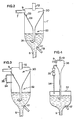
- a refrigeration system comprises a mixing and separating tank 1, a pump 2, a sublimator/evaporator coil 3, a conduit 4 connecting a bottom outlet 5 of the mixing and separating tank 1 with an inlet 6 of the evaporator coil via an inlet and an outlet of the pump 2, and a conduit 7 connecting an outlet 8 of the sublimator/evaporator coil 3 with an inlet 9 of the mixing and separating tank
- a compressor 10 has an inlet 11 connected to a top outlet 12 of the mixing and separating tank 1 by means of a conduit 13 and an outlet 14 connected to a condenser 15 followed by a receiver 16 which in its turn is connected to a bottom inlet 17 of the mixing and separating tank 1 via a valve 18 and by means of a conduit 19.
- a heat exchanger 20 is inserted in the conduits 13 and 19 such that carbon dioxide vapor flowing through the conduit 13 is heated by the liquid carbon dioxide flowing through the conduit 19. As a consequence of this superheating of the carbon dioxide vapor, the cost of the compressor 10 may be reduced substantially.
- a supply tank 21 is optionally provided for additional supply of liquid carbon dioxide on demand via a valve 22 into the conduit 19 and through the valve 18 to the bottom inlet 17 of the mixing and separating tank 1.
- the supply of liquid carbon dioxide from the supply tank 21 only takes place when the demand of liquid carbon dioxide is above the capacity of the compressor, i.e for top loads on the sublimator/evaporator 3.
- a conduit 23 connects the outlet of the pump 2 with a bottom inlet 24 of the mixing and separating tank 1 via a valve 25.
- the refrigeration system described operates as follows.
- the mixing and separating tank 1 contains a slurry of solid carbon dioxide particles in a liquid of d'limonene.
- the pump 2 sucks this slurry from the tank 1 via the bottom outlet 5 thereof such that the slurry is forced through the conduit 4 to the inlet 6 of the sublimator/evaporator coil 3, through this coil 3 to its outlet 8 and via the conduit 7 back to the inlet 9 of the mixing and separating tank 1.
- a fan blows air through the evaporator coil 3 such that the solid carbon dioxide particles entrained by the d'limonene transport fluid sublimate to carbon dioxide vapor during the passage through the sublimator/evaporator coil 3.
- the concentration of solid carbon dioxide in the refrigerant, i.e. the slurry of carbon dioxide particles in the d'limonene transport liquid, entering the evaporator coil.3 should be so high that an excess amount of solid carbon dioxide particles still is present in the effluent from the outlet 8 of the sublimator/evaporator coil 3. This excess of solid carbon dioxide particles ensures an efficient cooling of the whole internal area of the sublimator/evaporator coil 3.
- the risk of clogging of the solid carbon dioxide particles is completely eliminated.
- the flow of the slurry should always be upward or at least level from the pump 2 to and through the sublimator/evaporator 3.
- the risk of accumulation of the solid carbon dioxide particles at the bottom of the mixing and separating tank 1 is eliminated by the continuous agitation produced by that part of the slurry which is fed back to the bottom inlet 24 of the mixing and separating tank 1 by the pump 2 via the conduit 23 and the valve 25.
- agitation could be realized by other stirring media as well as by other means, such as mechanical means.
- the refrigerant returning into the mixing and separating tank 1 from the sublimator/evaporator coil 3 via the conduit 7 and the inlet 9 consists of liquid d'limonene, solid carbon dioxide particles and carbon dioxide vapor.
- the inlet 9 is positioned above the surface of the slurry in the mixing and separating tank 1 and directed tangentially such that the carbon dioxide vapor follows an upwardly directed path towards the top otlet 12 of the mixing and separating tank 1, while the d'limonene liquid and the solid carbon dioxide particles are injected into the slurry in the same tank 1.
- the compressor 10 sucks the substantially dry carbon dioxide vapor into its inlet 11 via the conduit 13 from the top outlet 12 of the mixing and separating tank 1, the carbon dioxide vapor being superheated in the heat exchanger 20, i.e. to a temperature of at leats - 50°C, in order to enable the compressor 10 to operate safely for a reasonable time. Also, this superheating makes it possible to use a compressor of less sophisticated design and thus of less cost.
- the liquid carbon dioxide fed from the receiver 16 via the conduit 19 and the valve 18 through the inlet 17 could be used as a heating medium in the heat exchanger 20.
- ammonia used in a prestage for cooling the condenser 15 may be used as the heating medium in the heat exchanger 20.
- the inlet 17 of the mixing and separating tank 1 is preferably a bottom inlet in order that the liquid carbon dioxide when injected therethrough and transformed into solid carbon dioxide and carbon dioxide vapor should act as a vigorous stirring medium in the slurry of solid carbon dioxide particles in liquid d'limonene, However, since the injection of liquid carbon dioxide may be discontinuous, that injection might take place at another position and the stirring effect thereof replaced by another stirring mechanism, such as described above. It should be noted that a substantial part of the liquid carbon dioxide is transformed into flash gas when introduced into the mixing and separating tank 1. This flash gas raises the pressure at the outlet 12 of the mixing and separating tank 1. In order not to overload the compressor 10, a valve 26 may be connected to the outlet 12 so as to vent carbon dioxide vapor from the mixing and separating tank 1 to the atmosphere when the pressure thereof exceeds a predetermined limit value.
- the momentary value of the vapor pressure inside the mixing and separating tank 1 could be used for regulating the valve 18 such that the pressure does not exceed the predetermined limit.
- the value of the pressure within the mixing and separating tank 1 could be used as input value to a PID regulator controlling the opening of the valve 18 via an electric motor.
- the refrigerant in the mixing and separating tank 1 should have such a carbon dioxide concentration that the refrigerant pumped into the sublimator/evaporator 3 is overfed with carbon dioxide and thereby cools all the internal surfaces of the sublimator efficiently.
- the concentration of solid carbon dioxide in the slurry fed into the sublimator/evaporator 3 may be controlled by the use of a light sensing device 27 to genrate a signal indicative of said concentration, e.g. indirectly by representing the turbidity of the slurry, for regulating the valve 18 by means of an appropriate control system 28 and thus the flow rate of liquid carbon dioxide supplied to the mixing tank 1.
- the temperature difference and/or the pressure difference between the inlet 6 and the outlet 8 of the sublimator/evaporator 3 may be used as a controlling input to the control system 28 in order to regulate the flow rate of liquid carbon dioxide supplied to the mixing tank 1.
- the mixing and separating tank 1 contains the separator as an upper part thereof, the lower part being used for mixing the solid carbon dioxide particles and the liquid brine for the transport of those particles.
- the separating and mixing functions are preferably performed in substantially separate vessels, as illustrated in FIGS. 2-4.
- a mixing and separating tank 1' has an inner funnel-shaped partition 29 forming the bottom of an upper separating section 30 and having a bottom outlet 31 submerged into the slurry in a lower mixing section 32. More than half of the liquid carbon dioxide introduced through the inlet 17 being vaporized, the partition 29 comprises a tangential vent 33 in order to equalize the pressures in the lower section 32 and the upper section 30.
- the flash gas thus generated in the lower section 32 passes through the vent 33 having the form of a nozzle such that the vapor is accelerated tangentially within the funnel-shaped upper section 30.
- the slurry in the lower section 32 is agitated by the liquid carbon dioxide from the inlet 17 and the resulting carbon dioxide vapor is centrifugally separated from any entrained droplets of brine before returning to the compressor 10 via the top outlet 12.
- the direct vent 33 into the upper section 30 can be replaced by a pipe 34 having a pressure regulator 35 such that a predetermined pressure difference may exist between the lower section 32 and the upper section 30 acting to pump the slurry out through the outlet 5 towards the pump 2.
- the pressure difference must be lower than the pressure from the column of slurry coming out of the funnel-shaped bottom part of the upper section 30.
- FIG. 4 Still another embodiment is illustrated in FIG. 4, wherein a first separate vessel 36 is used for the separation of the refrigerant returned from the sublimator/evaporator 3 via the inlet 9 and a second separat vessel 37 is used for the mixing of the solid carbon dioxide particles and the low temperature brine.
- a first separate vessel 36 is used for the separation of the refrigerant returned from the sublimator/evaporator 3 via the inlet 9
- a second separat vessel 37 is used for the mixing of the solid carbon dioxide particles and the low temperature brine.
- the pipe 34 and the pressure regulator 35 connect the first and second separate vessels 36 and 37 for the same purpose as in the embodiment shown in FIG. 3.
Landscapes
- Engineering & Computer Science (AREA)
- Chemical & Material Sciences (AREA)
- Combustion & Propulsion (AREA)
- Physics & Mathematics (AREA)
- Mechanical Engineering (AREA)
- Thermal Sciences (AREA)
- General Engineering & Computer Science (AREA)
- Organic Low-Molecular-Weight Compounds And Preparation Thereof (AREA)
- Devices That Are Associated With Refrigeration Equipment (AREA)
Description
Claims (21)
- A refrigeration system comprisinga mixing tank (1; 32; 32; 37) for a slurry of solid, sublimatable particles in a liquid, said mixing tank having first (1; 31; 31; 31; 31) and second (17) inlets and an outlet (5);a sublimator (3) having an inlet (6), an outlet (8) and several internal paths connecting the inlet (6) and the outlet (8);a first conduit (4) connecting the outlet (5) of the mixing tank (1; 32; 32; 37) to the inlet (6) of the sublimator (3) for the supply of said slurry of solid particles in a liquid to the sublimator;a separator (1; 30; 30; 36) having an inlet (9) and top (12) and bottom (1; 31; 31; 31) outlets;a second conduit (7) connecting the outlet (8) of the sublimator (3) to the inlet (9) of the separator (1; 30; 30; 36) for returning gas composed of sublimated particles and the slurry of still solid particles in the liquid from the sublimator (3) to the separator, the bottom outlet (1; 31; 31; 31) of the separator being connected to the first inlet (1; 31; 31; 31; 31) of the mixing tank (1; 32; 32; 37) for returning the slurry of still solid particles in the liquid to the mixing tank, the top outlet (12) of the separator ejecting the gas composed of sublimated particles;means (10, 11, 14-16, 20) connected to the second inlet (17) of the mixing tank (1; 32; 32; 37) to make up the sublimated solid particles ejected as gas from the top outlet (12) of the separator (1; 30; 30; 36); andfurther comprising means (23-25) for continuously agitating the slurry in the mixing tank (1; 32; 32; 37), whereby the system is characterised in that the mixing tank (1; 32; 32; 37) has a further inlet (24) below the level of the slurry and connected to a source (2) of a stirring medium.
- A refrigeration system as claimed in claim 1, comprising a pump (2) in the first conduit (4) for pumping the slurry from the mixing tank (1; 32; 32; 37) to and through the sublimator (3), said pump forming said source (2) and having an outlet connected to said further inlet (24) of the mixing tank (1; 32; 32; 37).
- A refrigeration system as claimed in claim 1, wherein the solid particles consist of carbon dioxide and the liquid is a low temperature brine.
- A refrigeration system as claimed in claim 3, wherein the liquid is d'limonene.
- A refrigeration system as claimed in claim 3, wherein the flow rate of carbon dioxide into the mixing tank (1; 32; 32; 37) is controlled in response to the difference between the temperature of the slurry at the inlet (6) of the sublimator (3) and the temperature of the slurry at the outlet (8) of the sublimator.
- A refrigeration system as claimed in claim 3, wherein the flow rate of carbon dioxide into the mixing tank (1; 32; 32; 37) is controlled in response to the difference between pressure at the inlet (6) of the sublimator (3) and the pressure at the outlet (8) of the sublimator.
- A refrigeration system as claimed in claim 5, wherein the flow rate of carbon dioxide into the mixing tank (1; 32; 32; 37) also is controlled in response to the difference between pressure at the inlet (6) of the sublimator (3) and the pressure at the outlet (8) of the sublimator.
- A refrigeration system as claimed in claim 2, wherein the first conduit (4) has no descending part between the pump (2) and the inlet (6) of the sublimator (3).
- A refrigeration system as claimed in claim 1, further comprising a compressor (10) having an inlet connected to the top outlet (12) of the separator (1; 30; 30; 36) and an outlet connected to the second inlet (17) of the mixing tank (1; 32; 32; 37).
- A refrigeration system as claimed in claim 1, further comprising a supply tank (21) of liquid carbon dioxide connected to the second inlet (17) of the mixing tank (1; 32; 32; 37).
- A refrigeration system as claimed in claim 10, further comprising a valve (22) controlling the flow rate of liquid carbon dioxide from the supply tank (21) .in response to a demand of liquid carbon dioxide above the capacity of the compressor (10).
- A refrigeration system as claimed in claim 11, further comprising a sensor (27) of the concentration of solid carbon dioxide at the outlet of the pump (2) for controlling the flow rate of liquid carbon dioxide supplied to the mixing tank (1; 32; 32; 37).
- A refrigeration system as claimed in claim 1, wherein the slurry contains solid carbon dioxide in excess such that also the effluent from the sublimator (3) contains solid carbon dioxide particles.
- A refrigeration system as claimed in claim 1, wherein the separator is contained in the mixing tank.
- A refrigeration system as claimed in claim 14, wherein the bottom outlet of the separator is submerged in the slurry in the mixing tank.
- A refrigeration system as claimed in claim 15, wherein the separator (30; 36) has a funnel-shaped bottom part (29).
- A refrigeration system as claimed in claim 16, wherein the funnel-shaped bottom part (29) forms a partition between the separator and the mixing tank.
- A refrigeration system as claimed in claim 14, wherein the separator is formed by an upper part of the mixing tank.
- A refrigeration system as claimed in claim 1, wherein the separator is in gas communication with an upper part of the mixing tank.
- A refrigeration system as claimed in claim 3, further comprising a pump (2) in the first conduit (4) for pumping the slurry from the mixing tank (1; 32; 32; 37) to and through the sublimator (3), and a compressor (10) having an inlet connected to the top outlet (12) of the separator (1; 30; 30; 36) and an outlet connected to the second inlet (17) of the mixing tank.
- A refrigeration system as claimed in claim 20, further comprising a sensor (27) of the concentration of solid carbon dioxide at the outlet of the pump (2) for controlling the flow rate of liquid carbon dioxide supplied to the mixing tank (1; 32; 32; 37).
Applications Claiming Priority (3)
| Application Number | Priority Date | Filing Date | Title |
|---|---|---|---|
| US752007 | 1996-11-15 | ||
| US08/752,007 US5715702A (en) | 1996-11-15 | 1996-11-15 | Refrigeration system |
| PCT/SE1997/001905 WO1998022764A1 (en) | 1996-11-15 | 1997-11-13 | A refrigeration system using a slurry of solid particles in a liquid |
Publications (2)
| Publication Number | Publication Date |
|---|---|
| EP0948727A1 EP0948727A1 (en) | 1999-10-13 |
| EP0948727B1 true EP0948727B1 (en) | 2004-04-21 |
Family
ID=25024453
Family Applications (1)
| Application Number | Title | Priority Date | Filing Date |
|---|---|---|---|
| EP97913622A Expired - Lifetime EP0948727B1 (en) | 1996-11-15 | 1997-11-13 | A refrigeration system using a slurry of solid particles in a liquid |
Country Status (8)
| Country | Link |
|---|---|
| US (1) | US5715702A (en) |
| EP (1) | EP0948727B1 (en) |
| JP (1) | JP2001504933A (en) |
| CN (1) | CN1120341C (en) |
| AU (1) | AU723840B2 (en) |
| CA (1) | CA2271934C (en) |
| DE (1) | DE69728790T2 (en) |
| WO (1) | WO1998022764A1 (en) |
Cited By (2)
| Publication number | Priority date | Publication date | Assignee | Title |
|---|---|---|---|---|
| EP2667116A1 (en) | 2012-05-21 | 2013-11-27 | Messer Group GmbH | Method and device for cooling |
| DE102019127488A1 (en) * | 2019-10-11 | 2021-04-15 | Technische Universität Dresden | Fluid circuit and method of operating the fluid circuit |
Families Citing this family (12)
| Publication number | Priority date | Publication date | Assignee | Title |
|---|---|---|---|---|
| US6516626B2 (en) | 2001-04-11 | 2003-02-11 | Fmc Corporation | Two-stage refrigeration system |
| WO2003062725A1 (en) * | 2002-01-18 | 2003-07-31 | Curtin University Of Technology | Process and device for production of lng by removal of freezable solids |
| EP1630495A1 (en) * | 2004-08-24 | 2006-03-01 | Nederlandse Organisatie voor toegepast-natuurwetenschappelijk Onderzoek TNO | A method and a cooling system in which a refrigerant is used as a cooling agent and/or as a defrosting agent |
| JP2006308176A (en) * | 2005-04-27 | 2006-11-09 | Taiyo Nippon Sanso Corp | Coolant, cooling method and coolant supply apparatus |
| JP2008224206A (en) * | 2008-04-02 | 2008-09-25 | Mayekawa Mfg Co Ltd | Dual refrigerating cycle device |
| FR2953370B1 (en) * | 2009-12-08 | 2012-08-03 | Air Liquide | METHOD AND INSTALLATION FOR COOLING AND / OR FREEZING PRODUCTS, IN PARTICULAR FOOD PRODUCTS, USING THE INJECTION OF TWO CRYOGENIC LIQUIDS |
| US8597386B2 (en) * | 2010-05-06 | 2013-12-03 | Alliant Techsystems Inc. | Method and system for continuously pumping a solid material and method and system for hydrogen formation |
| DK201570281A1 (en) * | 2015-05-13 | 2016-11-28 | Nel Hydrogen As | Cooling of a fluid with a refrigerant at triple point |
| DE102016105334B4 (en) * | 2015-12-15 | 2020-08-20 | Institut Für Luft- Und Kältetechnik Gemeinnützige Gmbh | Process for cryogenic cooling |
| EP4095459A1 (en) * | 2018-03-30 | 2022-11-30 | IHI Corporation | Cooling system |
| DE102019123723B4 (en) * | 2019-09-04 | 2024-06-13 | Institut Für Luft- Und Kältetechnik Gemeinnützige Gmbh | Sublimation coolers and cryogenic cooling processes |
| DE102019126214A1 (en) * | 2019-09-27 | 2021-04-01 | Technische Universität Dresden | Device for transferring heat in a fluid circuit and method for operating the device |
Family Cites Families (13)
| Publication number | Priority date | Publication date | Assignee | Title |
|---|---|---|---|---|
| US3558731A (en) * | 1968-09-18 | 1971-01-26 | Shell Oil Co | Paraxylene crystallization |
| US3788091A (en) * | 1970-09-25 | 1974-01-29 | Statham Instrument Inc | Thermodynamic cycles |
| US3767724A (en) * | 1971-10-15 | 1973-10-23 | Chevron Res | Extractive crystallization method for the separation of mixtures of alkenes and alkanes |
| US3906742A (en) * | 1972-12-04 | 1975-09-23 | Borg Warner | Air conditioning system utilizing ice slurries |
| US3869870A (en) * | 1973-07-02 | 1975-03-11 | Borg Warner | Refrigeration system utilizing ice slurries |
| US4226089A (en) * | 1978-06-30 | 1980-10-07 | Barrow Billy E | Waste heat recovery device |
| US4224801A (en) * | 1978-11-13 | 1980-09-30 | Lewis Tyree Jr | Stored cryogenic refrigeration |
| ES479676A1 (en) * | 1979-04-18 | 1980-01-01 | Liquid Carbonic De Espana S A | A METHOD OF OBTAINING LOW TEMPERATURES. |
| US5035733A (en) * | 1987-07-17 | 1991-07-30 | Sunwell Engineering Company Ltd. | Ice storage and distribution unit |
| FR2619203B1 (en) * | 1987-08-04 | 1989-11-17 | Anhydride Carbonique Ind | CRYOGENIC COOLING PROCESS AND INSTALLATION USING LIQUID CARBON DIOXIDE AS A REFRIGERANT |
| GB2258298B (en) * | 1991-07-31 | 1995-05-17 | Star Refrigeration | Cooling method and apparatus |
| US5205135A (en) * | 1991-11-13 | 1993-04-27 | Liquid Carbonic Corporation | Helical conveyor freezer |
| NL9401324A (en) * | 1994-08-16 | 1996-04-01 | Urenco Nederland Bv | Cooling process and cooling installation |
-
1996
- 1996-11-15 US US08/752,007 patent/US5715702A/en not_active Expired - Lifetime
-
1997
- 1997-11-13 JP JP52355898A patent/JP2001504933A/en active Pending
- 1997-11-13 CN CN97199763A patent/CN1120341C/en not_active Expired - Fee Related
- 1997-11-13 DE DE69728790T patent/DE69728790T2/en not_active Expired - Lifetime
- 1997-11-13 WO PCT/SE1997/001905 patent/WO1998022764A1/en not_active Ceased
- 1997-11-13 CA CA002271934A patent/CA2271934C/en not_active Expired - Fee Related
- 1997-11-13 EP EP97913622A patent/EP0948727B1/en not_active Expired - Lifetime
- 1997-11-13 AU AU50761/98A patent/AU723840B2/en not_active Ceased
Cited By (2)
| Publication number | Priority date | Publication date | Assignee | Title |
|---|---|---|---|---|
| EP2667116A1 (en) | 2012-05-21 | 2013-11-27 | Messer Group GmbH | Method and device for cooling |
| DE102019127488A1 (en) * | 2019-10-11 | 2021-04-15 | Technische Universität Dresden | Fluid circuit and method of operating the fluid circuit |
Also Published As
| Publication number | Publication date |
|---|---|
| CN1238036A (en) | 1999-12-08 |
| CA2271934A1 (en) | 1998-05-28 |
| EP0948727A1 (en) | 1999-10-13 |
| AU5076198A (en) | 1998-06-10 |
| WO1998022764A1 (en) | 1998-05-28 |
| DE69728790D1 (en) | 2004-05-27 |
| DE69728790T2 (en) | 2004-10-07 |
| US5715702A (en) | 1998-02-10 |
| AU723840B2 (en) | 2000-09-07 |
| JP2001504933A (en) | 2001-04-10 |
| CN1120341C (en) | 2003-09-03 |
| CA2271934C (en) | 2007-01-23 |
Similar Documents
| Publication | Publication Date | Title |
|---|---|---|
| US5715702A (en) | Refrigeration system | |
| CA1173738A (en) | Heat exchange methods and apparatus | |
| JP4027990B2 (en) | Cooling system and separation device therefor | |
| GB2036278A (en) | Stored cryogenic refrigeration | |
| CA1227709A (en) | Dual vessel heat exchange systems | |
| US5319940A (en) | Defrosting method and apparatus for a refrigeration system | |
| US4551981A (en) | Heat exchange methods and apparatus | |
| US4545134A (en) | Dual vessel heat exchange systems | |
| EP0756691B1 (en) | Refrigeration system | |
| JPH06174348A (en) | Method and device for circulating heat transfer fluid and cooling heat load | |
| US3592017A (en) | Purging arrangement for refrigeration systems | |
| EP0795110B1 (en) | Vapour compression system and method of operating the same | |
| US5934095A (en) | Versatile low temperature liquid CO2 ground support system | |
| EP3246641A1 (en) | Apparatus for rapid defrosting of the evaporator in an air-water heat pump | |
| US3837175A (en) | Refrigeration system having improved heat transfer and reduced power requirements | |
| CA1125040A (en) | Freezing or cooling plant comprising an oil separator | |
| US4476695A (en) | Refrigerator condensation apparatus | |
| CA1053602A (en) | Refrigeration type water desalinisation units | |
| CA1300901C (en) | Method and apparatus for the utilization of the heat of melting of water | |
| KR0133424B1 (en) | Refrigerant distribution structure of refrigeration unit | |
| US1735611A (en) | Apparatus for conditioning air | |
| MXPA97004716A (en) | Va compression system | |
| GB2331354A (en) | Liquid cooling devices |
Legal Events
| Date | Code | Title | Description |
|---|---|---|---|
| PUAI | Public reference made under article 153(3) epc to a published international application that has entered the european phase |
Free format text: ORIGINAL CODE: 0009012 |
|
| 17P | Request for examination filed |
Effective date: 19990426 |
|
| AK | Designated contracting states |
Kind code of ref document: A1 Designated state(s): DE DK ES FI FR GB IT NL SE |
|
| RIN1 | Information on inventor provided before grant (corrected) |
Inventor name: CRASK, ROGER, PAUL Inventor name: LUHM, GARY, WALTER Inventor name: STRONG, JOHN, RICHARD |
|
| RIN1 | Information on inventor provided before grant (corrected) |
Inventor name: CRASK, ROGER, PAUL Inventor name: LUHM, GARY, WALTER Inventor name: STRONG, JOHN, RICHARD |
|
| 17Q | First examination report despatched |
Effective date: 20020225 |
|
| GRAP | Despatch of communication of intention to grant a patent |
Free format text: ORIGINAL CODE: EPIDOSNIGR1 |
|
| GRAS | Grant fee paid |
Free format text: ORIGINAL CODE: EPIDOSNIGR3 |
|
| GRAA | (expected) grant |
Free format text: ORIGINAL CODE: 0009210 |
|
| AK | Designated contracting states |
Kind code of ref document: B1 Designated state(s): DE DK ES FI FR GB IT NL SE |
|
| PG25 | Lapsed in a contracting state [announced via postgrant information from national office to epo] |
Ref country code: NL Free format text: LAPSE BECAUSE OF FAILURE TO SUBMIT A TRANSLATION OF THE DESCRIPTION OR TO PAY THE FEE WITHIN THE PRESCRIBED TIME-LIMIT Effective date: 20040421 Ref country code: IT Free format text: LAPSE BECAUSE OF FAILURE TO SUBMIT A TRANSLATION OF THE DESCRIPTION OR TO PAY THE FEE WITHIN THE PRESCRIBED TIME-LIMIT;WARNING: LAPSES OF ITALIAN PATENTS WITH EFFECTIVE DATE BEFORE 2007 MAY HAVE OCCURRED AT ANY TIME BEFORE 2007. THE CORRECT EFFECTIVE DATE MAY BE DIFFERENT FROM THE ONE RECORDED. Effective date: 20040421 Ref country code: FI Free format text: LAPSE BECAUSE OF FAILURE TO SUBMIT A TRANSLATION OF THE DESCRIPTION OR TO PAY THE FEE WITHIN THE PRESCRIBED TIME-LIMIT Effective date: 20040421 |
|
| REG | Reference to a national code |
Ref country code: GB Ref legal event code: FG4D |
|
| REF | Corresponds to: |
Ref document number: 69728790 Country of ref document: DE Date of ref document: 20040527 Kind code of ref document: P |
|
| PG25 | Lapsed in a contracting state [announced via postgrant information from national office to epo] |
Ref country code: SE Free format text: LAPSE BECAUSE OF FAILURE TO SUBMIT A TRANSLATION OF THE DESCRIPTION OR TO PAY THE FEE WITHIN THE PRESCRIBED TIME-LIMIT Effective date: 20040721 Ref country code: DK Free format text: LAPSE BECAUSE OF FAILURE TO SUBMIT A TRANSLATION OF THE DESCRIPTION OR TO PAY THE FEE WITHIN THE PRESCRIBED TIME-LIMIT Effective date: 20040721 |
|
| PG25 | Lapsed in a contracting state [announced via postgrant information from national office to epo] |
Ref country code: ES Free format text: LAPSE BECAUSE OF FAILURE TO SUBMIT A TRANSLATION OF THE DESCRIPTION OR TO PAY THE FEE WITHIN THE PRESCRIBED TIME-LIMIT Effective date: 20040801 |
|
| NLV1 | Nl: lapsed or annulled due to failure to fulfill the requirements of art. 29p and 29m of the patents act | ||
| ET | Fr: translation filed | ||
| PLBE | No opposition filed within time limit |
Free format text: ORIGINAL CODE: 0009261 |
|
| STAA | Information on the status of an ep patent application or granted ep patent |
Free format text: STATUS: NO OPPOSITION FILED WITHIN TIME LIMIT |
|
| 26N | No opposition filed |
Effective date: 20050124 |
|
| PGFP | Annual fee paid to national office [announced via postgrant information from national office to epo] |
Ref country code: FR Payment date: 20101202 Year of fee payment: 14 |
|
| PGFP | Annual fee paid to national office [announced via postgrant information from national office to epo] |
Ref country code: GB Payment date: 20101124 Year of fee payment: 14 |
|
| REG | Reference to a national code |
Ref country code: FR Ref legal event code: ST Effective date: 20120731 |
|
| PG25 | Lapsed in a contracting state [announced via postgrant information from national office to epo] |
Ref country code: FR Free format text: LAPSE BECAUSE OF NON-PAYMENT OF DUE FEES Effective date: 20111130 |
|
| PGFP | Annual fee paid to national office [announced via postgrant information from national office to epo] |
Ref country code: DE Payment date: 20121128 Year of fee payment: 16 |
|
| GBPC | Gb: european patent ceased through non-payment of renewal fee |
Effective date: 20121113 |
|
| PG25 | Lapsed in a contracting state [announced via postgrant information from national office to epo] |
Ref country code: GB Free format text: LAPSE BECAUSE OF NON-PAYMENT OF DUE FEES Effective date: 20121113 |
|
| PG25 | Lapsed in a contracting state [announced via postgrant information from national office to epo] |
Ref country code: DE Free format text: LAPSE BECAUSE OF NON-PAYMENT OF DUE FEES Effective date: 20140603 |
|
| REG | Reference to a national code |
Ref country code: DE Ref legal event code: R119 Ref document number: 69728790 Country of ref document: DE Effective date: 20140603 |