EP0948436B1 - Fillerless writing instrument - Google Patents
Fillerless writing instrument Download PDFInfo
- Publication number
- EP0948436B1 EP0948436B1 EP97949480A EP97949480A EP0948436B1 EP 0948436 B1 EP0948436 B1 EP 0948436B1 EP 97949480 A EP97949480 A EP 97949480A EP 97949480 A EP97949480 A EP 97949480A EP 0948436 B1 EP0948436 B1 EP 0948436B1
- Authority
- EP
- European Patent Office
- Prior art keywords
- ink
- writing
- writing instrument
- end portion
- supply rod
- Prior art date
- Legal status (The legal status is an assumption and is not a legal conclusion. Google has not performed a legal analysis and makes no representation as to the accuracy of the status listed.)
- Expired - Lifetime
Links
Images


Classifications
-
- B—PERFORMING OPERATIONS; TRANSPORTING
- B43—WRITING OR DRAWING IMPLEMENTS; BUREAU ACCESSORIES
- B43K—IMPLEMENTS FOR WRITING OR DRAWING
- B43K8/00—Pens with writing-points other than nibs or balls
- B43K8/02—Pens with writing-points other than nibs or balls with writing-points comprising fibres, felt, or similar porous or capillary material
- B43K8/04—Arrangements for feeding ink to writing-points
- B43K8/06—Wick feed from within reservoir to writing-points
- B43K8/08—Wick separate from writing-points
-
- B—PERFORMING OPERATIONS; TRANSPORTING
- B43—WRITING OR DRAWING IMPLEMENTS; BUREAU ACCESSORIES
- B43K—IMPLEMENTS FOR WRITING OR DRAWING
- B43K7/00—Ball-point pens
- B43K7/10—Arrangements for feeding ink to the ball points
Definitions
- the present application relates to a writing instrument, and more particularly to a fillerless writing instrument having a venting mechanism.
- Baffle or fin-type venting mechanisms are common to writing instruments. These mechanisms are typically used in fillerless-type writing instruments to prevent ink leakage at varying ambient temperatures. Typically, filler-type writing instruments incorporate a porous filler material for containing the ink supply, whereas fillerless writing instruments incorporate an ink reservoir in combination with an ink transport system to carry the ink from the reservoir to the writing point.
- Fillerless writing instruments exhibit several advantages over filler-type writing instruments. These advantages include an improved ink flow over the life of the writing instrument, and a greater utilization of the ink charge. For example, in filler-type writing instruments, often a substantial portion of the ink charge can be wasted as a result of the ink retention properties of the filler material. With fillerless writing instruments, most of the ink is usable and control of the usage is significantly better than with filler-type instruments.
- U.S. Patent No. 4,671,692 to Inaba discloses a writing pen having a flow-regulator having a labyrinth groove in its circumference interposed between a writing tip and an ink reservoir in a pen barrel in which an ink supply rod is inserted into the bore of the flow-regulator to guide ink to the writing tip.
- a body includes a labyrinth groove defined by a plurality of fins.
- a second ink supply rod made of porous material has a larger diameter than the first ink supply rod and guides ink to a third ink supply rod to thereby guide ink to the writing tip.
- U.S. Patent No 4,671,692 discloses a writing instrument as recited in the preamble of claim 1.
- U.S. Patent No 4,382,707 to Anderka discloses a writing instrument having a single ink supply rod.
- This arrangement has several inherent disadvantages.
- the supply rod would necessarily be of significant length in order to feed ink directly from the ink reservoir to the writing point.
- To deliver ink to the writing point in specific amounts over such a great distance involves a loss of control and therefore may result in overfeeding or underfeeding the writing point with ink.
- U.S. Patent No 4,239,408 to Mutschler discloses a writing instrument having an ink supply system having a flow controlling member, and an ink feeding member.
- the flow controlling member supplies ink from the reservoir to the ink feeding member.
- the ink feeding member supplies ink to the writing point.
- the flow controlling member has an effective flow section smaller than the flow section in the feeding member.
- Mutschler discloses a feed bar for venting ink having a spiral groove extending from the ink reservoir to an open orifice adjacent the point.
- the uniform nature of the groove does not provide structure to reduce the probability of excess ink entering the groove from flowing to the point.
- the present invention relates to a writing instrument which avoids the above described disadvantages by providing first and second ink supply rods to provide a predetermined and consistent flow of ink as may be required.
- the writing instrument also incorporates structure to vent the ink supply to prevent the ink from leaking from the point of the writing instrument while enhancing the transport of ink with relative precision.
- a writing instrument is provided according to claim 1.
- anterior will refer to the end of the writing instrument which is closest to the writing point, while the term “posterior” will refer to the end which is further from the writing point.
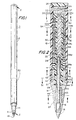
- FIG. 1 a first preferred embodiment of the subject writing instrument is illustrated in FIG. 1, and is designated generally by reference numeral 10.
- Writing instrument 10 includes barrel 12 and writing tip 14.
- Writing point support member 16 extends anteriorly from writing tip 14 and supports writing point 18 as shown.
- Venting mechanism 20 (illustrated generally in phantom lines in FIG. 1) is positioned within barrel 12 adjacent the anterior end portion thereof.
- Barrel 12 defines elongated chamber 22 which includes ink reservoir 24 extending therethrough toward the posterior end portion.
- Ink reservoir 24 is integrally formed by chamber 22 and is positioned between the venting mechanism 20 at the anterior end portion, and the end cap 26 at the posterior end.
- Support body 28 extends longitudinally within venting mechanism 20 and includes a plurality of outwardly extending fins in the form of annular disc-like support rings 34a, 34b, 34c, 34d and 34e spaced apart from each other and extending circumferentially about the central support body 28 as shown in FIG. 2.
- each adjacent pair of the annular support rings Positioned between each adjacent pair of the annular support rings is a plurality of annular disc-like fins 32, spaced longitudinally from each other and extending in a similar fashion annularly around the support body.
- Each plurality of such fins 32 is selectively numbered and the numbers in each group differ from the next adjacent group. In particular, the number of fins 32 is greatest at the posterior end of the venting mechanism 20 and least at the anterior end of the venting mechanism 20, with the most anteriorly positioned group containing four fins.
- Venting mechanism 20 is positioned within barrel 12 between ink reservoir 24 and writing tip 14.
- Venting mechanism 20, including support body 28 and disc-like fins 32 is preferably injection molded from ABS, polyacetal, nylon, or other engineering thermoplastics.
- Tubular body 28 defines an axial ink supply bore 30 extending longitudinally therethrough.
- a plurality of spaced apart disc-like fins 32 and a plurality of thicker annular rings 34a, 34b, 34c, 34d, and 34e extend radially outwardly from, and circumferentially surround support body 28 and respectfully define a plurality of annular channels 36 therebetween.
- Annular rings 34a, 34b, 34c, 34d, and 34e are preferably formed monolithically with support body 28 and provide support for venting mechanism 20 with respect to barrel 12. As shown, disc-like fins 32 are positioned in groupings between rings 34a, 34b, 34c, 34d, and 34e. The longitudinal spacing between fins 32 increases from the posterior end of venting mechanism 20 to the anterior end thereof, i.e. the annular channels 36 increase in width from the posterior end to the anterior end of the venting mechanism 20. Aperture 37 is defined at the posterior end portion of venting mechanism 18. Aperture 37 is preferably of a lesser dimension than ink supply bore 30 and communicates with ink reservoir 24.
- Cylindrical neck 42 extends from the anterior end of elongated body 28 and is received in bore 44 formed by a plurality of splines 43a in the posterior portion of writing tip 14 as will be described in further detail.
- Reception bore 44 communicates with axial chamber 46 which accommodates point support member 16.
- Axial chamber 46 communicates with axial ink supply bore 30 in venting mechanism 20.
- Ink supply rod 48 is positioned within ink supply bore 30 and extends through tubular body 28.
- Ink supply rod 48 is preferably fabricated from an extruded or molded polyester or polyacrylic material. The posterior end of ink supply rod 48 is in communication with ink reservoir 24 through aperture 37 in tubular body 28.
- ink supply rod 48 may alternatively define a longitudinal bore to convey ink, preferably the rod 48 does not have a thru-bore and conveys ink through the bundle of fibers formed either by a molding or an extrusion process.
- Rod 48 is positioned at the anterior end portion of the instrument for reception of point connector rod 50, which is a fibrous rod that transports ink from ink supply rod 48 to writing point 18.
- Point connector rod 50 is preferably made of extruded polyester fibers and has a smaller cross-sectional dimension as shown, than ink supply rod 48 and thereby a smaller ink capacity.
- the rod is preferably first extruded, then cut and ground at each end.
- the lesser dimension of point connector rod 50 permits writing tip 14 and point support 16 to be designed to comfortably fit in the user's hand while adequately supplying writing tip 14 with ink.
- the greater dimension of ink supply rod 48 permits sufficient ink to be transferred directly from ink reservoir 24 to connector rod 50 and thereby to point 18 than would be possible with a single narrow ink supply rod.
- the larger cross-section of rod 48 allows rod 50 to be inserted into the anterior end of rod 48 and thus penetrate rod 48. This feature increases the resistance of the system to mechanical shock by the improved junction between rod 48 and rod 50.
- the materials of ink supply rod 48 and point connector rod 50 will be selected in order to provide a consistent flow of ink to writing point 18, based upon the viscosity and capillary properties of the ink used in writing instrument 10.
- Polyester is preferred.
- polyacrylic, polyacetal, polyethylene, polypropylene or nylon may be utilized.
- Either of the rods may either be extruded or sintered molded.
- the resinous material is heated sufficiently to be extruded as separate fibers, then partially cooled, and then caused to adhere to each other to form a bundle of fibers having ink passages extending therethrough.
- the sintered molding process the resinous material is placed in a mold and heated until it becomes tacky, but not molten. Thereafter, the material is cooled to form a generally porous rod in which a multiplicity of open interstices are formed to permit the passage of ink.
- posterior annular ring 34a defines a double peripheral seal 38 with the inner wall portion of barrel 12.
- Ink groove 40 is defined in posterior annular ring 34a, and extends from a posterior surface adjacent ink reservoir 24 to a posterior surface adjacent posteriormost aperture 37.
- each of the disc-like fins 32 and annular rings 34b, 34c, and 34d defines an ink groove 52 and an air groove 54 at opposite sides of the circumference.
- the system of air grooves as shown form a continuous and serpentine path which communicates the outside atmosphere with the ink supply without causing flow of ink into the air system.
- air groove 54 is greater in width than ink groove 52.
- air groove 56 is formed at a peripheral portion of the anteriormost annular ring 34e.
- Air groove 56 in ring 34e is positioned in line with ink grooves 52 in rings 34b.
- Central opening 61 of cylindrical wall 43 defines an air gap between wall 43 and cylindrical neck 42 which is divided into a plurality of air passages 61a defined and positioned by and between a plurality of longitudinal splines 43a within central opening 61 as shown clearly in FIG. 5a.
- the line of demarcation between cylindrical wall 43 and spline 43a is shown schematically by dashed lines on each side.
- Air passages 61a communicate with air slot 65 which in turn communicates via a slot (not shown) with vent hole 67 at a position 180° opposite slot 65.
- Rings 34b between section 4-4 and section 5-5 in FIG. 2 each have air slots 54 as shown in FIG. 4, while ring 34e below section 5-5 in FIG. 2 includes air slot 56 positioned 180° from air slots 54.
- a continuous but circuitous air path is defined from ink reservoir 24 to rings 34a, 34b, 34c, 34d and 34e to passages 61a, air slot 65 and finally to air slot 67 which communicates with the outside atmosphere.
- This circuitous passage permits air venting of the ink system while preventing ink from flowing freely out of the writing instrument.
- Lines 2-2 in FIG. 5a are shown to illustrate further the cross-section shown in FIG. 2.
- Ink grooves 52 and air grooves 54 and 56 interconnect annular channels 36 such that ink may flow from ink reservoir 24 into venting mechanism 20 when a positive pressure is produced in ink reservoir 24 such as at elevated ambient temperatures.
- air may be introduced into venting mechanism 20 adjacent writing tip 14 via the circuitous path described above. More particularly, ink flow resulting from this increased pressure flows into ink groove 40 by capillary action and subsequently into posteriormost annular channel 36. Given sufficient pressure, ink will continue to flow through groove 52 towards the anterior portion of venting mechanism 20.
- the increase in spacing of fins 32 from the posterior end to the anterior end has the effect of reducing the probability of ink leakage from the ink reservoir 24 to the anterior end of venting mechanism 20 and the writing point 18 by initially filling the spaces at the posterior end.
- the writing instrument 10 of the present invention provides improved ink flow without vulnerability to shock, while providing a circuitous air path from the writing tip to the ink reservoir, to permit expansion and contraction of the ink system without loss of the requisite precise ink flow.
- the structure of the system as described permits the ink flow to the writing point with extreme precision, while providing the above-noted advantages.
- FIG. 7 there is illustrated a second preferred embodiment of the subject writing instrument, designated generally by reference numeral 100.
- Writing instrument 100 is constructed substantially as described above with respect to writing instrument 10, with the distinctions noted hereinbelow.
- point support member 116 has an elongated posterior support portion 160 which extends into air gap 58 defined between tubular body 28 and point connector rod 50.
- Posterior support portion 160 is preferably constructed of a rigid material, such as an engineering plastic.
- Posterior support portion 160 at least partially surrounds point connector rod 50 and prevents rod 50 from buckling during assembly of writing instrument 100 as well as during normal use thereof.
- Air venting is provided by slot 65 which communicates with air passages 61a as in the embodiment shown in FIG. 2.
- the writing instrument includes a point connector rod of relatively narrow cross-sectional dimension, yet having an anterior portion which supports the writing point with substantial strength and rigidity. This feature makes it possible to reduce the outer anterior dimension of the instrument sufficiently, to accommodate the user's grip thus enhancing the ergonomic character of the instrument.
- the embodiment of FIG. 7 is identical to the embodiment of FIG. 2.
Landscapes
- Pens And Brushes (AREA)
- Mechanical Pencils And Projecting And Retracting Systems Therefor, And Multi-System Writing Instruments (AREA)
- Inks, Pencil-Leads, Or Crayons (AREA)
- Radar Systems Or Details Thereof (AREA)
- Charge And Discharge Circuits For Batteries Or The Like (AREA)
- Electrotherapy Devices (AREA)
- Vehicle Body Suspensions (AREA)
- Medicinal Preparation (AREA)
- Photographic Developing Apparatuses (AREA)
- Control And Other Processes For Unpacking Of Materials (AREA)
Abstract
Description
Claims (14)
- A writing instrument (10), which comprises:characterized in that:a) a barrel (12) defining an internal passage (22) including an ink reservoir (24);b) a venting mechanism (20) positioned at least partially within said internal passage (22) of said barrel (12) adjacent an anterior end portion thereof, said venting mechanism including:i) an elongated body (28) defining an axial bore (30) therethrough in communication with said ink reservoir; andii) a plurality of spaced apart fins (34a,34e) peripherally surrounding and extending outwardly from said elongated body (28) and defining a plurality of annular channels (36) between said fins, said fins defining a groove (52) thereon to interconnect said annular channels;c) a point support member (16) supporting a writing point (18) and positioned adjacent an anterior end portion of said venting mechanism (20) and defining an axial bore aligned with said axial bore (30) of said elongated body;d) a first ink supply rod (48) disposed within said axial bore (30) of said elongated body (28) and having a posterior end portion in direct communication with said ink reservoir (24) to convey ink from said ink reservoir to an anterior end portion thereof, said first supply rod (48) extending from said ink reservoir to a location at least approximately one half the distance between said ink reservoir and said writing point (18); ande) a second ink supply rod (50) disposed at least partially within said bore (30) of said elongated body (28) and within said bore of said point support member (16), said second ink supply rod (50) being in direct contact with said first ink supply rod (48) and said writing point (18) for conveying ink from said first ink supply rod (48) to said writing point (18),and in that, the point support member (16) and the writing tip (14) are adapted to define a circuitous air path from the anterior portion of the writing tip (14) to said venting mechanism.said second ink supply rod (50) have a cross-sectional dimension less than the cross-sectional dimension of said first ink supply rod (48),said writing instrument further comprises a writing tip (14) having:a posterior portion comprising a wall (43) which extends within said internal passage (22) of the barrel, said wall (43) defining a reception bore (44) for receiving a cylindrical neck (42) which extends from the anterior end of the elongated body (28),an anterior portion defining an axial chamber (46) which accomodates a portion of the point support member (16), said axial chamber (46) communicating with said axial bore (30) of said elongated body (28),
- The writing instrument according to claim 1, wherein said spaced apart fins (34a,34e) define spaces which increase from a posterior end portion of said venting mechanism (20) to an anterior end portion thereof.
- The writing instrument according to claim 1 or claim 2, wherein said internal passage (22) of said barrel (12) is configured and dimensioned to receive an anterior end portion of said elongated body (28) of said venting mechanism.
- The writing instrument according to any one of the preceding claims, wherein said first supply rod (48) is extruded from a material selected from the group consisting of polyester, polyacrylic, polyacetal, polyethylene, polypropylene and nylon.
- The writing instrument according to any one of the preceding claims, wherein said second supply rod (50) is extruded from a material selected from a material selected from the group consisting of polyacetal, polyethylene, polypropylene, polyester, polyacrylic and nylon.
- The writing instrument according to any one of claims 1 to 3, wherein said first supply rod (48) is molded from a material selected from the group consisting of polyester, polyacrylic, polyacetal, polyethylene, polypropylene and nylon.
- The writing instrument according to any one of claims 1, 2, 3, 4 and 6, wherein said second supply rod (50) is molded from a material selected from the group consisting of polyacetal, polyethylene, polypropylene, polyester, polyacrylic and nylon.
- The writing instrument according to any one of preceding claims, wherein said support member (16) comprises a posterior end portion which extends at least partially within said axial bore (30) of said elongated body (28) of the venting mechanism so as to be supported thereby.
- The writing instrument according to claim 8, wherein said posterior end portion of said point support member (16) is constructed of a rigid material.
- The writing instrument according to any one of preceding claims, wherein said venting mechanism further comprises a seal (38) disposed at a posterior end portion of said venting mechanism (20) between said barrel and a posterior-most fin, said posterior-most fin defining a groove (40) between said ink reservoir and said annular channels.
- The writing instrument according to any one of preceding claims, wherein said support member (16) extends into said internal passage (22) of said barrel to a location at least equal to about one half the.length of said second ink supply rod (50) so as to provide support for said anterior end portion of said venting mechanism (20) and said anterior end portion of second ink supply rod (50).
- The writing instrument according to any one of preceding claims, wherein said reception bore (44) of the writing tip (14) defines an air gap between said wall (43) and the cylindrical neck (42) of the elongated body (28).
- The writing instrument according to claim 12, wherein said reception bore (44) of the posterior portion of the writing tip (44) is formed by a plurality of splines (43a) which define a plurality of air passages (61a).
- The writing instrument according to claim 13, wherein said air passages (61a) communicate with an air slot (65) formed in the axial chamber (46) of the writing tip and the anterior end of said writing tip (14) defines a vent hole (67) with the point support member (16), said vent hole (67) communicating with the outside atmosphere.
Applications Claiming Priority (3)
| Application Number | Priority Date | Filing Date | Title |
|---|---|---|---|
| US08/735,230 US5906446A (en) | 1996-10-22 | 1996-10-22 | Fillerless writing instrument |
| US735230 | 1996-10-22 | ||
| PCT/US1997/021120 WO1998017482A1 (en) | 1996-10-22 | 1997-10-21 | Fillerless writing instrument |
Publications (2)
| Publication Number | Publication Date |
|---|---|
| EP0948436A1 EP0948436A1 (en) | 1999-10-13 |
| EP0948436B1 true EP0948436B1 (en) | 2004-09-08 |
Family
ID=24954870
Family Applications (1)
| Application Number | Title | Priority Date | Filing Date |
|---|---|---|---|
| EP97949480A Expired - Lifetime EP0948436B1 (en) | 1996-10-22 | 1997-10-21 | Fillerless writing instrument |
Country Status (20)
| Country | Link |
|---|---|
| US (1) | US5906446A (en) |
| EP (1) | EP0948436B1 (en) |
| JP (1) | JP2001502619A (en) |
| KR (1) | KR100354841B1 (en) |
| CN (1) | CN1082906C (en) |
| AT (1) | ATE275483T1 (en) |
| AU (1) | AU720203B2 (en) |
| BR (1) | BR9713488A (en) |
| CA (1) | CA2269609C (en) |
| CZ (1) | CZ133799A3 (en) |
| DE (1) | DE69730614T2 (en) |
| ES (1) | ES2226003T3 (en) |
| GT (1) | GT199700111A (en) |
| NO (1) | NO991892L (en) |
| NZ (1) | NZ335238A (en) |
| PL (1) | PL186812B1 (en) |
| PT (1) | PT948436E (en) |
| RU (1) | RU2153987C1 (en) |
| TW (1) | TW378180B (en) |
| WO (1) | WO1998017482A1 (en) |
Families Citing this family (39)
| Publication number | Priority date | Publication date | Assignee | Title |
|---|---|---|---|---|
| EP1066981A4 (en) * | 1998-03-26 | 2004-03-31 | Mitsubishi Pencil Co | Writing implement equipped with ink reservoir |
| JP3536673B2 (en) * | 1998-07-28 | 2004-06-14 | 昌旦 深見 | Pen |
| JP2000233592A (en) * | 1999-02-17 | 2000-08-29 | Pilot Ink Co Ltd | Direct liquid writing instrument |
| DK1050417T3 (en) * | 1999-05-07 | 2001-08-13 | Universal Spa | Pen with felt tip or similar writing utensils and method of making them |
| JP3801819B2 (en) * | 1999-10-05 | 2006-07-26 | パイロットインキ株式会社 | Water discoloration toy set |
| US6224284B1 (en) | 1999-10-12 | 2001-05-01 | Dri Mark Products Incorporated | Metallic ink composition for wick type writing instruments |
| TW534002U (en) * | 1999-12-16 | 2003-05-21 | Mitsubishi Pencil Co | Collector type writing implement |
| JP3477130B2 (en) * | 1999-12-16 | 2003-12-10 | 三菱鉛筆株式会社 | Direct liquid writing instrument |
| JP3524832B2 (en) * | 1999-12-16 | 2004-05-10 | 三菱鉛筆株式会社 | Direct liquid writing instrument |
| US6503965B1 (en) * | 2000-08-24 | 2003-01-07 | Bic Corporation | Solvent-based non-fluorescent ink for writing instruments based upon pigment dispersions in non-aqueous solvents |
| US6425948B1 (en) * | 2000-08-24 | 2002-07-30 | Bic Corporation | Solvent-based fluorescent inks for writing instruments based upon pigment dispersions in non-aqueous solvents |
| US6503017B1 (en) * | 2002-01-22 | 2003-01-07 | Chen-Chou Liu | Ink regulating apparatus in a pen |
| US6964534B2 (en) * | 2003-06-26 | 2005-11-15 | Binney & Smith Inc. | Retractable writing instrument |
| US20070274765A1 (en) * | 2003-06-26 | 2007-11-29 | Crayola Llc | Retractable writing instrument |
| US7481858B2 (en) * | 2005-02-25 | 2009-01-27 | Societe Bic | Hydrogen generating fuel cell cartridges |
| JP4601551B2 (en) * | 2003-09-05 | 2010-12-22 | 三菱鉛筆株式会社 | Applicator |
| US7322375B2 (en) * | 2004-04-30 | 2008-01-29 | Vanderbilt University | High bandwidth rotary servo valves |
| US7175267B2 (en) * | 2004-05-05 | 2007-02-13 | Monitek Electronics Limited | Ink cartridge |
| KR100562280B1 (en) * | 2004-06-15 | 2006-03-23 | 주식회사모나미 | Writing utensils |
| US7727293B2 (en) * | 2005-02-25 | 2010-06-01 | SOCIéTé BIC | Hydrogen generating fuel cell cartridges |
| WO2007027820A2 (en) * | 2005-08-30 | 2007-03-08 | Flynn Jerome R | Precision liquid applicator and applicator head |
| US7850382B2 (en) * | 2007-01-18 | 2010-12-14 | Sanford, L.P. | Valve made from two materials and writing utensil with retractable tip incorporating same |
| US7488130B2 (en) | 2007-02-01 | 2009-02-10 | Sanford, L.P. | Seal assembly for retractable instrument |
| USD607054S1 (en) * | 2008-02-08 | 2009-12-29 | J.S. Staedtler Gmbh & Co. Kg | Instrument for writing, drawing or painting |
| US8226312B2 (en) * | 2008-03-28 | 2012-07-24 | Sanford, L.P. | Valve door having a force directing component and retractable instruments comprising same |
| US8221012B2 (en) | 2008-11-07 | 2012-07-17 | Sanford, L.P. | Retractable instruments comprising a one-piece valve door actuating assembly |
| US8393814B2 (en) | 2009-01-30 | 2013-03-12 | Sanford, L.P. | Retractable instrument having a two stage protraction/retraction sequence |
| EP2431192B1 (en) * | 2010-09-15 | 2015-05-27 | Tung Yik International Ltd. | Writing pen with ink storage |
| WO2015060078A1 (en) * | 2013-10-21 | 2015-04-30 | 有限会社Vスパーク | Pressure fluctuation buffering mechanism and applicator |
| JP6367561B2 (en) * | 2014-01-20 | 2018-08-01 | 株式会社呉竹 | Writing instrument refill and writing instrument |
| JP6514480B2 (en) * | 2014-10-16 | 2019-05-15 | 株式会社呉竹 | Ink filler |
| JP6630473B2 (en) * | 2014-10-16 | 2020-01-15 | 株式会社呉竹 | Pens and pen refills |
| JP1575856S (en) * | 2016-06-21 | 2017-05-08 | ||
| CN108312735B (en) * | 2018-03-29 | 2024-01-09 | 真彩文具股份有限公司 | Ink pen with capillary ceramic ball |
| EP3815921A1 (en) | 2019-10-29 | 2021-05-05 | Société BIC | Nib for writing felt pen |
| EP4112329A1 (en) * | 2021-06-30 | 2023-01-04 | Société BIC | Nib drying delay component for a free-ink writing instrument |
| US20250033402A1 (en) * | 2021-12-08 | 2025-01-30 | Kabushiki Kaisha Pilot Corporation (Also Trading As Pilot Corporation) | Writing implement |
| AU2023202359A1 (en) * | 2022-04-20 | 2023-11-09 | Beijing Wenhaiyang Industry Trading Co., Ltd | Output device for uniformly mixed liquid and method for making and using the same |
| JP7715356B2 (en) * | 2023-01-10 | 2025-07-30 | ▲ケン▼瓏實業股▲分▼有限公司 | Biodegradable Marker Pens |
Family Cites Families (79)
| Publication number | Priority date | Publication date | Assignee | Title |
|---|---|---|---|---|
| DE1250302B (en) * | 1967-09-14 | Fa A W. Faber-Castell, Stein bei Nürnberg | Full, drawing or writing pen with a wick as a writing element | |
| DE173131C (en) * | ||||
| NL63900C (en) * | 1944-04-10 | |||
| US2612867A (en) * | 1948-08-23 | 1952-10-07 | Parker Pen Co | Fountain pen |
| US3340560A (en) * | 1964-02-21 | 1967-09-12 | Platinum Pen Co Ltd | Fiber tip writing utensils |
| DE1259733B (en) * | 1964-11-04 | 1968-01-25 | Helmut Bross Dipl Ing | Ink feed for fountain pens |
| US3598494A (en) * | 1968-08-28 | 1971-08-10 | Edward Bok | Drafting pen with dried ink collector |
| DE1911951A1 (en) * | 1969-03-10 | 1970-09-24 | Riepe Werk | Tube pen with insertable tube pen tip |
| CA1008016A (en) * | 1972-09-18 | 1977-04-05 | Edward Bok | Pen with ink injection system |
| US3947137A (en) * | 1973-12-18 | 1976-03-30 | The Sailor Pen Co., Ltd. | Socket for a ball point pen |
| US3957379A (en) * | 1975-04-04 | 1976-05-18 | The Parker Pen Company | Fountain pen |
| US3951555A (en) * | 1975-04-14 | 1976-04-20 | The Parker Pen Company | Modular writing pen |
| US4753546A (en) * | 1978-02-14 | 1988-06-28 | Koh-I-Noor Rapidograph, Inc. | Pressure balanced stylographic pen |
| DE7806264U1 (en) * | 1978-03-02 | 1978-06-22 | Mutschler, Philipp, 6900 Heidelberg | Ink regulators for writing implements |
| DE2909472C2 (en) * | 1979-03-10 | 1982-12-23 | Pelikan Ag, 3000 Hannover | Ink cartridge fountain pen |
| US4930921A (en) * | 1980-03-10 | 1990-06-05 | Koh-I-Noor Rapidograph, Inc. | Tubular writting pen with superposed pressure equalization chambers |
| DE3010944C2 (en) * | 1980-03-21 | 1985-08-08 | Rotring-Werke Riepe Kg, 2000 Hamburg | Writing implement |
| JPS608239B2 (en) * | 1980-07-10 | 1985-03-01 | 株式会社 トンボ鉛筆 | low viscosity ink writing instrument |
| JPS6136387Y2 (en) * | 1980-11-13 | 1986-10-22 | ||
| DE3110199C1 (en) * | 1981-03-17 | 1983-01-13 | Otto 6900 Heidelberg Mutschler | Writing tip for a writing instrument with a tube nib |
| AU6942281A (en) * | 1981-04-10 | 1982-10-14 | Tsai, K.L. | Ball-point pen |
| JPS5878799A (en) * | 1981-11-02 | 1983-05-12 | 東京焼結金属株式会社 | Pen lead body |
| DE3207219A1 (en) * | 1982-02-27 | 1983-10-13 | Geha-Werke Gmbh, 3000 Hannover | Writing instrument, especially writing cartridge |
| CA1209093A (en) * | 1982-03-16 | 1986-08-05 | Thomas D. Hall | Writing instruments and their manufacture |
| EP0091610B1 (en) * | 1982-03-30 | 1986-06-04 | Anweiler, Walter, Ing. (grad.) | Feeding conduit for a fountain pen |
| JPS58192084U (en) * | 1982-06-16 | 1983-12-20 | シヤチハタ工業株式会社 | Pen tip for ballpoint pen |
| DE3224611A1 (en) * | 1982-07-01 | 1984-01-05 | Tsai, Kuo Lung, Taipei, Taiwan | WRITING INSTRUMENT WITH SEVERAL INTERCHANGEABLE WRITING TIPS |
| JPS5921985U (en) * | 1982-08-03 | 1984-02-10 | ぺんてる株式会社 | writing implements |
| US4565463A (en) * | 1983-03-20 | 1986-01-21 | Pentel Kabushiki Kaisha | Aqueous ink cartridge with two part vent plug |
| FR2546823B1 (en) * | 1983-06-03 | 1989-02-17 | Pilot Pen Co Ltd | FEATHER CORE FOR A WRITING INSTRUMENT |
| DE3321301A1 (en) * | 1983-06-13 | 1984-12-13 | Montblanc-Simplo Gmbh, 2000 Hamburg | INK SUPPLY SYSTEM FOR WRITING INSTRUMENTS WORKING WITH LIQUID INK |
| JPS6021260A (en) * | 1983-07-15 | 1985-02-02 | Nippon Telegr & Teleph Corp <Ntt> | Gradation recording system |
| DE3338227C2 (en) * | 1983-10-21 | 1985-11-28 | Mutschler, Otto, 6900 Heidelberg | Ink pens for writing implements |
| DE3415859C2 (en) * | 1984-04-28 | 1991-10-10 | Schmidt Feintechnik GmbH, 7742 St Georgen | Plotter pen |
| US4572691A (en) * | 1984-07-02 | 1986-02-25 | Minnesota Mining And Manufacturing Company | Pen-like instrument for applying correction fluid |
| DE3429031A1 (en) * | 1984-08-07 | 1986-02-20 | Walter Ing.(grad.) 6907 Nußloch Anweiler | Fountain pen |
| JPS6145191U (en) * | 1984-08-29 | 1986-03-25 | パイロツトインキ株式会社 | writing implements |
| DE3442331A1 (en) * | 1984-11-20 | 1986-05-22 | Hans Joachim Ing.(grad.) 3000 Hannover Witte | Ink conductor, having a compensating body enclosing it, for writing appliances with ink in a free form and a large ink-storage space |
| DE3445944C1 (en) * | 1984-12-17 | 1986-06-05 | Otto 6900 Heidelberg Mutschler | Ink pipe for tube recorders |
| DE3527694A1 (en) * | 1985-08-02 | 1987-02-12 | Rotring Werke Riepe Kg | TUBE RECORDER TIP |
| US4770558A (en) * | 1986-02-20 | 1988-09-13 | Gebr. Schmidt KG Fabrik Fuer Feinmechanik | Ink writing or drawing instrument |
| JPH0667677B2 (en) * | 1986-03-14 | 1994-08-31 | テイボ−株式会社 | Liquid supplier |
| JPS6345095A (en) * | 1986-08-13 | 1988-02-26 | 株式会社 寿 | writing implements |
| DE8631592U1 (en) * | 1986-11-26 | 1987-12-23 | J. S. Staedtler GmbH & Co, 8500 Nürnberg | Writing tip or recording element |
| JPS63180279U (en) * | 1987-05-12 | 1988-11-21 | ||
| GB2207396B (en) * | 1987-06-26 | 1992-01-29 | Pilot Ink Co Ltd | Writing instrument. |
| US5290117A (en) * | 1987-06-26 | 1994-03-01 | Pilot Ink Co., Ltd. | Penpoint assembly and writing instrument employing the same |
| DE3736954C1 (en) * | 1987-10-31 | 1988-12-15 | Montblanc Simplo Gmbh | Ink line for a fountain pen |
| GB2213107B (en) * | 1987-12-07 | 1992-06-03 | Shizuo Yamanaka | Multiangular pen |
| US5000606A (en) * | 1988-05-07 | 1991-03-19 | Koh-I-Noor Rapidograph, Inc. | Drop-weight and tubular writing instrument |
| KR960002247B1 (en) * | 1988-07-30 | 1996-02-14 | 펜텔 가부시기가이샤 | Temporary ink storage member and writing utensil using it |
| JPH0288793U (en) * | 1988-12-27 | 1990-07-13 | ||
| DE3912411C1 (en) * | 1989-04-15 | 1990-09-13 | Dataprint Datendrucksysteme R. Kaufmann Kg, 2000 Hamburg, De | |
| DE3921005A1 (en) * | 1989-06-27 | 1991-01-10 | Rotring Werke Riepe Kg | TUBE RECORDER TIP |
| DE3926271A1 (en) * | 1989-08-09 | 1991-02-14 | Geha Werke Gmbh | Ink duct for fountain pen - consists of series of interconnected discs placed one upon another |
| US5217313A (en) * | 1989-09-29 | 1993-06-08 | Pentel Kabushiki Kaisha | Writing instrument |
| JPH088866Y2 (en) * | 1990-04-25 | 1996-03-13 | パイロットプレシジョン株式会社 | Pen core for writing instruments |
| DE4013510C2 (en) * | 1990-04-27 | 1995-04-20 | Rotring Int Gmbh | Tube pen tip, especially for use in drawing plotters |
| DE4018598A1 (en) * | 1990-06-09 | 1991-12-12 | Otto Mutschler | WRITING UNIT FOR A CARTRIDGE FILLER |
| JPH066087B2 (en) * | 1990-06-20 | 1994-01-26 | 有限会社ムクサ | Lotion applicator |
| DE4024382C1 (en) * | 1990-08-01 | 1992-08-27 | Pelikan Ag, 3000 Hannover, De | |
| DE4115685C3 (en) * | 1991-05-14 | 2001-07-05 | Dataprint Datendrucksysteme R | Writing instrument with writing fluid freely contained in a container |
| RU2051803C1 (en) * | 1991-06-05 | 1996-01-10 | Анатолий Семенович Лихоманов | Ball pen |
| JPH0535374U (en) * | 1991-10-09 | 1993-05-14 | 国吉 塩満 | Fountain pen |
| DE4201268A1 (en) * | 1992-01-18 | 1993-07-22 | Rotring Werke Riepe Kg | Technical drawing writing implement - has writing point at front end connected to ink storage chamber and with axially extending pressure compensation chamber |
| JPH06127186A (en) * | 1992-10-14 | 1994-05-10 | Tombow Pencil Co Ltd | Low viscosity ink writing instrument |
| DE4243686C2 (en) * | 1992-12-18 | 1996-12-12 | Rotring Int Gmbh | Ink or ink pen |
| JP3179229B2 (en) * | 1993-02-18 | 2001-06-25 | 三菱鉛筆株式会社 | A method of fixing a shaft body having a collector structure and a relay core in a writing instrument |
| US5336009A (en) * | 1993-05-10 | 1994-08-09 | Jean Young | Ink guide for a ballpoint pen |
| JP2534821B2 (en) * | 1993-05-13 | 1996-09-18 | 二郎 堀 | Writing instrument |
| JP2605170Y2 (en) * | 1993-07-30 | 2000-06-26 | ぺんてる株式会社 | Writing implement |
| US5551789A (en) * | 1993-10-13 | 1996-09-03 | Kawakami Giken Co Ltd | Cosmetic material container |
| GB9325891D0 (en) * | 1993-12-17 | 1994-02-23 | Parker Pen Bv | Writing instruments |
| JP3197427B2 (en) * | 1994-03-16 | 2001-08-13 | 三菱鉛筆株式会社 | Writing implement |
| CA2143518C (en) * | 1994-03-16 | 1999-03-09 | Kazuaki Matsumoto | Writing implement |
| FR2719806B1 (en) * | 1994-05-11 | 1996-08-02 | Conte | Writing article in liquid ink, in particular solvent-based. |
| JP3479755B2 (en) * | 1994-06-06 | 2003-12-15 | パイロットインキ株式会社 | Ballpoint pen |
| DE19529865C2 (en) * | 1995-08-14 | 2002-02-28 | Kaufmann R Dataprint | Device for applying liquids to a base by means of an application element |
| DE19610644A1 (en) * | 1996-03-07 | 1997-09-11 | Rotring Int Gmbh | Ball-point pen with rearward tip-linked ink capillary and air channel |
-
1996
- 1996-10-22 US US08/735,230 patent/US5906446A/en not_active Expired - Lifetime
-
1997
- 1997-10-17 GT GT199700111A patent/GT199700111A/en unknown
- 1997-10-21 RU RU99111080/12A patent/RU2153987C1/en not_active IP Right Cessation
- 1997-10-21 CN CN97180745A patent/CN1082906C/en not_active Expired - Lifetime
- 1997-10-21 BR BR9713488-0A patent/BR9713488A/en not_active IP Right Cessation
- 1997-10-21 TW TW086115470A patent/TW378180B/en active
- 1997-10-21 AT AT97949480T patent/ATE275483T1/en not_active IP Right Cessation
- 1997-10-21 AU AU68113/98A patent/AU720203B2/en not_active Expired
- 1997-10-21 CZ CZ991337A patent/CZ133799A3/en unknown
- 1997-10-21 EP EP97949480A patent/EP0948436B1/en not_active Expired - Lifetime
- 1997-10-21 CA CA002269609A patent/CA2269609C/en not_active Expired - Lifetime
- 1997-10-21 KR KR1019997003503A patent/KR100354841B1/en not_active Expired - Lifetime
- 1997-10-21 JP JP10519759A patent/JP2001502619A/en active Pending
- 1997-10-21 WO PCT/US1997/021120 patent/WO1998017482A1/en not_active Ceased
- 1997-10-21 PL PL97333281A patent/PL186812B1/en not_active IP Right Cessation
- 1997-10-21 ES ES97949480T patent/ES2226003T3/en not_active Expired - Lifetime
- 1997-10-21 DE DE69730614T patent/DE69730614T2/en not_active Expired - Lifetime
- 1997-10-21 PT PT97949480T patent/PT948436E/en unknown
- 1997-10-21 NZ NZ335238A patent/NZ335238A/en unknown
-
1999
- 1999-04-21 NO NO991892A patent/NO991892L/en not_active Application Discontinuation
Also Published As
| Publication number | Publication date |
|---|---|
| PT948436E (en) | 2005-01-31 |
| CA2269609A1 (en) | 1998-04-30 |
| KR20000052707A (en) | 2000-08-25 |
| KR100354841B1 (en) | 2002-10-05 |
| ATE275483T1 (en) | 2004-09-15 |
| WO1998017482A1 (en) | 1998-04-30 |
| NO991892L (en) | 1999-06-22 |
| CZ133799A3 (en) | 1999-12-15 |
| BR9713488A (en) | 2000-02-29 |
| DE69730614T2 (en) | 2005-09-22 |
| HK1024671A1 (en) | 2000-10-20 |
| AU720203B2 (en) | 2000-05-25 |
| NZ335238A (en) | 2000-03-27 |
| DE69730614D1 (en) | 2004-10-14 |
| ES2226003T3 (en) | 2005-03-16 |
| CN1082906C (en) | 2002-04-17 |
| TW378180B (en) | 2000-01-01 |
| EP0948436A1 (en) | 1999-10-13 |
| JP2001502619A (en) | 2001-02-27 |
| RU2153987C1 (en) | 2000-08-10 |
| PL333281A1 (en) | 1999-11-22 |
| PL186812B1 (en) | 2004-02-27 |
| GT199700111A (en) | 1999-04-10 |
| NO991892D0 (en) | 1999-04-21 |
| AU6811398A (en) | 1998-05-15 |
| CA2269609C (en) | 2003-09-16 |
| CN1240387A (en) | 2000-01-05 |
| US5906446A (en) | 1999-05-25 |
Similar Documents
| Publication | Publication Date | Title |
|---|---|---|
| AU720203B2 (en) | Fillerless writing instrument | |
| US4671692A (en) | Writing pen holder with three wicks | |
| US3951555A (en) | Modular writing pen | |
| EP0624483B1 (en) | Writing instrument | |
| US4239408A (en) | Fountain pen with improved ink flow control | |
| EP0256615A1 (en) | Writing utensil | |
| US6276860B1 (en) | Liquid applicator | |
| JP2524018B2 (en) | Ink writing instrument | |
| AU748530B2 (en) | Fillerless writing instrument | |
| US5951187A (en) | Fluid flow regulator and writing pen | |
| US3592552A (en) | Writing instrument | |
| MXPA99003701A (en) | Fillerless writing instrument | |
| CA2223135C (en) | Direct ink storing type writing instrument | |
| US2766729A (en) | Fountain pen | |
| US4776718A (en) | Writing implement | |
| KR200175747Y1 (en) | Ink Outflow Structure of Water-based Ink Ballpoint Pen | |
| JP2000079787A (en) | Writing utensil | |
| HUP9903029A2 (en) | Fillerless writing instrument |
Legal Events
| Date | Code | Title | Description |
|---|---|---|---|
| PUAI | Public reference made under article 153(3) epc to a published international application that has entered the european phase |
Free format text: ORIGINAL CODE: 0009012 |
|
| 17P | Request for examination filed |
Effective date: 19990413 |
|
| AK | Designated contracting states |
Kind code of ref document: A1 Designated state(s): AT DE ES FI FR GB GR IE IT PT SE |
|
| 17Q | First examination report despatched |
Effective date: 19991209 |
|
| GRAP | Despatch of communication of intention to grant a patent |
Free format text: ORIGINAL CODE: EPIDOSNIGR1 |
|
| GRAS | Grant fee paid |
Free format text: ORIGINAL CODE: EPIDOSNIGR3 |
|
| GRAA | (expected) grant |
Free format text: ORIGINAL CODE: 0009210 |
|
| AK | Designated contracting states |
Kind code of ref document: B1 Designated state(s): AT DE ES FI FR GB GR IE IT PT SE |
|
| PG25 | Lapsed in a contracting state [announced via postgrant information from national office to epo] |
Ref country code: FI Free format text: LAPSE BECAUSE OF FAILURE TO SUBMIT A TRANSLATION OF THE DESCRIPTION OR TO PAY THE FEE WITHIN THE PRESCRIBED TIME-LIMIT Effective date: 20040908 Ref country code: AT Free format text: LAPSE BECAUSE OF FAILURE TO SUBMIT A TRANSLATION OF THE DESCRIPTION OR TO PAY THE FEE WITHIN THE PRESCRIBED TIME-LIMIT Effective date: 20040908 |
|
| REG | Reference to a national code |
Ref country code: GB Ref legal event code: FG4D |
|
| REG | Reference to a national code |
Ref country code: IE Ref legal event code: FG4D |
|
| REF | Corresponds to: |
Ref document number: 69730614 Country of ref document: DE Date of ref document: 20041014 Kind code of ref document: P |
|
| PG25 | Lapsed in a contracting state [announced via postgrant information from national office to epo] |
Ref country code: IE Free format text: LAPSE BECAUSE OF NON-PAYMENT OF DUE FEES Effective date: 20041021 |
|
| PGFP | Annual fee paid to national office [announced via postgrant information from national office to epo] |
Ref country code: GR Payment date: 20041027 Year of fee payment: 8 |
|
| PGFP | Annual fee paid to national office [announced via postgrant information from national office to epo] |
Ref country code: PT Payment date: 20041130 Year of fee payment: 8 |
|
| PG25 | Lapsed in a contracting state [announced via postgrant information from national office to epo] |
Ref country code: SE Free format text: LAPSE BECAUSE OF FAILURE TO SUBMIT A TRANSLATION OF THE DESCRIPTION OR TO PAY THE FEE WITHIN THE PRESCRIBED TIME-LIMIT Effective date: 20041208 |
|
| REG | Reference to a national code |
Ref country code: GR Ref legal event code: EP Ref document number: 20040403603 Country of ref document: GR |
|
| REG | Reference to a national code |
Ref country code: PT Ref legal event code: SC4A Effective date: 20041123 |
|
| REG | Reference to a national code |
Ref country code: ES Ref legal event code: FG2A Ref document number: 2226003 Country of ref document: ES Kind code of ref document: T3 |
|
| PLBE | No opposition filed within time limit |
Free format text: ORIGINAL CODE: 0009261 |
|
| STAA | Information on the status of an ep patent application or granted ep patent |
Free format text: STATUS: NO OPPOSITION FILED WITHIN TIME LIMIT |
|
| ET | Fr: translation filed | ||
| REG | Reference to a national code |
Ref country code: IE Ref legal event code: MM4A |
|
| 26N | No opposition filed |
Effective date: 20050609 |
|
| PG25 | Lapsed in a contracting state [announced via postgrant information from national office to epo] |
Ref country code: PT Free format text: LAPSE BECAUSE OF NON-PAYMENT OF DUE FEES Effective date: 20060421 |
|
| REG | Reference to a national code |
Ref country code: PT Ref legal event code: MM4A Effective date: 20060421 |
|
| PG25 | Lapsed in a contracting state [announced via postgrant information from national office to epo] |
Ref country code: GR Free format text: LAPSE BECAUSE OF NON-PAYMENT OF DUE FEES Effective date: 20040908 |
|
| REG | Reference to a national code |
Ref country code: GB Ref legal event code: 732E Free format text: REGISTERED BETWEEN 20100610 AND 20100616 |
|
| PGFP | Annual fee paid to national office [announced via postgrant information from national office to epo] |
Ref country code: IT Payment date: 20101027 Year of fee payment: 14 |
|
| PGFP | Annual fee paid to national office [announced via postgrant information from national office to epo] |
Ref country code: ES Payment date: 20101026 Year of fee payment: 14 |
|
| REG | Reference to a national code |
Ref country code: FR Ref legal event code: TP Owner name: BIC CORPORATION, US Effective date: 20120420 |
|
| PG25 | Lapsed in a contracting state [announced via postgrant information from national office to epo] |
Ref country code: IT Free format text: LAPSE BECAUSE OF NON-PAYMENT OF DUE FEES Effective date: 20111021 |
|
| REG | Reference to a national code |
Ref country code: ES Ref legal event code: FD2A Effective date: 20130531 |
|
| PG25 | Lapsed in a contracting state [announced via postgrant information from national office to epo] |
Ref country code: ES Free format text: LAPSE BECAUSE OF NON-PAYMENT OF DUE FEES Effective date: 20111022 |
|
| REG | Reference to a national code |
Ref country code: FR Ref legal event code: PLFP Year of fee payment: 19 |
|
| REG | Reference to a national code |
Ref country code: FR Ref legal event code: PLFP Year of fee payment: 20 |
|
| PGFP | Annual fee paid to national office [announced via postgrant information from national office to epo] |
Ref country code: DE Payment date: 20161027 Year of fee payment: 20 Ref country code: FR Payment date: 20161025 Year of fee payment: 20 Ref country code: GB Payment date: 20161027 Year of fee payment: 20 |
|
| REG | Reference to a national code |
Ref country code: DE Ref legal event code: R071 Ref document number: 69730614 Country of ref document: DE |
|
| REG | Reference to a national code |
Ref country code: GB Ref legal event code: PE20 Expiry date: 20171020 |
|
| PG25 | Lapsed in a contracting state [announced via postgrant information from national office to epo] |
Ref country code: GB Free format text: LAPSE BECAUSE OF EXPIRATION OF PROTECTION Effective date: 20171020 |