EP0948280B1 - A toilet seat adapted to extract odours - Google Patents
A toilet seat adapted to extract odours Download PDFInfo
- Publication number
- EP0948280B1 EP0948280B1 EP97910560A EP97910560A EP0948280B1 EP 0948280 B1 EP0948280 B1 EP 0948280B1 EP 97910560 A EP97910560 A EP 97910560A EP 97910560 A EP97910560 A EP 97910560A EP 0948280 B1 EP0948280 B1 EP 0948280B1
- Authority
- EP
- European Patent Office
- Prior art keywords
- seat
- aperture
- toilet
- toilet seat
- extraction device
- Prior art date
- Legal status (The legal status is an assumption and is not a legal conclusion. Google has not performed a legal analysis and makes no representation as to the accuracy of the status listed.)
- Expired - Lifetime
Links
Images






Classifications
-
- E—FIXED CONSTRUCTIONS
- E03—WATER SUPPLY; SEWERAGE
- E03D—WATER-CLOSETS OR URINALS WITH FLUSHING DEVICES; FLUSHING VALVES THEREFOR
- E03D9/00—Sanitary or other accessories for lavatories ; Devices for cleaning or disinfecting the toilet room or the toilet bowl; Devices for eliminating smells
- E03D9/04—Special arrangement or operation of ventilating devices
- E03D9/05—Special arrangement or operation of ventilating devices ventilating the bowl
- E03D9/052—Special arrangement or operation of ventilating devices ventilating the bowl using incorporated fans
-
- A—HUMAN NECESSITIES
- A47—FURNITURE; DOMESTIC ARTICLES OR APPLIANCES; COFFEE MILLS; SPICE MILLS; SUCTION CLEANERS IN GENERAL
- A47K—SANITARY EQUIPMENT; ACCESSORIES THEREFOR, e.g. TOILET ACCESSORIES
- A47K13/00—Seats or covers for all kinds of closets
- A47K13/24—Parts or details not covered in, or of interest apart from, groups A47K13/02 - A47K13/22
- A47K13/30—Seats having provisions for heating, deodorising or the like, e.g. ventilating, noise-damping or cleaning devices
- A47K13/307—Seats with ventilating devices
Definitions
- the invention relates to odour venting apparatus for a toilet, in particular, but not exclusively to domestic toilets, in particular, but not exclusively to the path of airflow across the apparatus when in use.
- US patent number US-A-1 794 635 shows a similar arrangement to GB-A-2 266 901 with a series of apertures forming a hollow channel around the sides of the underside of the seat.
- US patent number US-A- 3,916,459 shows an apparatus for venting the toilet bowl of noxious odours that includes a conduit formed within the toilet seat, interconnecting the toilet bowl chamber and an opening in the toilet seat axle.
- a toilet seat as defined in claim 1.
- the closure means comprises an apertured tube substantially concentric with the hinge, the hinge being capable of movement between first and second positions, in the first position both the aperture of the hinge and the aperture of the tube overlap to some degree and in the second position no such overlap occurs.
- the hinge and seat are so linked that movement of the hinge between first and second positions results from a rotary motion about the axis of the hinge caused by the raising and lowering of the seat
- the underside of the seat comprises two independent substantially continuous lips that underlie the seat, each of which terminate at the head of the seat, each lip being so designed to substantially overlie the top of the bowl in a contiguous relationship and to contact or otherwise mate with that portion of the hinge that secures the toilet seat to the bowl.
- the head of the seat is recessed to allow ease of raising and lowering of the lid.
- the hinge-incorporated aperture is substantially centrally located.
- the toilet seat incorporates an extraction device capable of "sucking" odours through the aperture and venting them away from the vicinity of the toilet seat once said extraction device has been actuated.
- the extraction device comprises a housing fitted with an air mover, a power supply and control circuitry for the air mover, connection means connecting the housing to the toilet seat and preferably part of the housing in use, is provided with an essentially static "air-pocket" which surrounds the air mover.
- a portion of the housing is cone shaped, the slope of the cone being in the range of 40 - 50° with respect to the mouth of the housing.
- the external size of the housing has substantially the dimensions of a standard 6-inch bathroom tile.
- At least some of the visible parts of the extraction device in use are made from Acrylonitrile Butadiene Styrene
- the extraction device further comprises a sleeve which in use, is generally concentric with and adjacent the air mover.
- the sleeve is made from Poly Vinyl Chloride.
- the sleeve terminates in a reticulated wall vent.
- the extraction device is actuated by disruption of an infrared beam i.e. the control circuitry receives an input from an infrared sensor.
- the seat is solid in cross-section.
- the invention also includes within its scope a toilet bowl incorporating a toilet seat as specified above.
- integral is intended to cover not only something which is formed from the outset as one single-entity component but also anything which, whilst being assembled from a plurality of initially disparately-produced integers, ends up as one overall and normally non-dismantleable structure.
- toilet seat is intended to cover the lid 2 the hinge 4 and hinge block 5 and seat 3.
- FIG 1 shows the toilet seat, generally referenced I in a raised and lowered position respectively.
- the toilet seat 1 comprises a lid 2, a seat 3 and a hinge 4.
- the hinge 4 is integral with the hinge block 5, the latter, in use, being used to secure the toilet seat 1 to the toilet bowl 50 via conventional "nut and bolt” or other fixing means, (again not illustrated)
- the seat 3 is provided with two independent lips 6 integral with the under side of the seat 3.
- the hinge 4 is substantially cylindrical and is apertured.
- the seat 3 is integral with that part of the hinge 4 that is apertured and lifting the seat 3 as can be seen clearly in Figure 1 alters the position of the hinge aperture (in other words, rotating the seat 3 about the longitudinal axis of the hinge 4). It will also be noted that the apertured portion of the hinge 4 that is integral with the seat 3 is also free to rotate about the hinge block 5 in a conventional manner.
- the hinge 4 essentially comprises three components, an inner portion that is integral with the seat 3 and is apertured, that is free to rotate about the longitudinal axis of the hinge 4 and two outer non apertured components 36 that are also free to rotate about the longitudinal axis of the hinge 4 and are integral with the lid 2.
- an inner cylindrical tube 7 is permanently fixed or secured in position via conventional fixing means such as glue or welds but it will also be noted that the tube 7 is apertured. In alternative embodiments, the tube 7 may be demountable and fitted into place with for example, a grub screw.
- the size of the aperture is larger than the hinge aperture but as can clearly be seen in Figure 1, when the seat 3 is in the lowered position, the hinge aperture is wholly enclosed by the tube aperture providing a pathway denoted by the letter "B".
- Figure 1 also illustrates the seat in a raised position and as can be seen, once the seat is raised, the hinge aperture is completely out of phase with the tube aperture closing the pathway denoted by the letter "B".
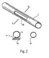
- Figure 2 illustrates the tube 7 in a perspective view and it shows the tube aperture 10 centrally located in the wall of the tube.
- Figure 2 also illustrates the central portion of the hinge 4 (i.e., that part of the hinge that is integral with the seat 3) together with the hinge block 5 in cross section.
- Figure 2 is a cross sectional view along the line DD of the tube 7. It will be noted that the aperture 10 is larger than the aperture 11.
- FIG. 3 illustrates another perspective view of the seat 3 in cross section but this time seen from the "front" of the seat 3.
- a further portion of the seat 3 has been removed and this is the portion denoted by the letter "A" between the "squiggly lines".
- the plane of the mouth of the aperture 10 bisects the seat 3 between the angles specified above. In this particular embodiment, the angle is 45°.
- the under side 6 of the seat 3 is also provided with a resiliently flexible material 14 that extends slightly beyond the plane of the under side 6 of the seat 3 and is designed to overlie the top surface of the toilet bowl (not illustrated) when the seat 3 is lowered.
- the weight of an individual sat on the seat 3 will force the resiliently flexible material 14 into a temporary substantially "air-tight" seal around the top surface of the toilet bowl (not illustrated).
- Figure 4 shows the seat 3 viewed from the under side clearly illustrating the location of the lips 6 and resiliently flexible material 14
- the under side of the seat comprises two continuous lips 6 that underlie the seat, each of which terminate at the "head” of the under side of the seat 3.
- the resiliently flexible material 14 and the mating action of the lips 6 with the hinge block 5 when an individual sits on the seat 3, substantially, the only means of air-flow across the under side of the seat 3 is through the "mouth" of the "head” of the under side of the seat 3.
- Figure 5 shows the toilet seat 1 replete with lid 2, seat 3, hinge 4 and hinge block 5, the lid 2 being in the "closed” position
- the lid 2 is provided with two rubber teats 8 so positioned to come in contact with either side of the top surface of the seat 3 so that the lid 2 does not mar or chip the top surface of the seat 3 if the lid 2 is inadvertently "dropped” down on to the seat 3
- the clearance between the lid 2 and the seat 3 as a result of the teats 8 is less than 1 cm and in this embodiment is approximately 5 mm.
- the lid 2 is also provided with a recess 9 at its head to enable an individual to lift the lid 2 with ease by inserting one's fingers under the recess 9. Although not clearly illustrated, the head of the lid 2 passes beyond the mouth of the seat 3 so that when "looking-down" on the lid 2 in Figure 5, the mouth of the seat 3 cannot be seen at all.
- Figure 6 shows a plan view of the under side of the lid 2 of the toilet seat 1 and also shows the outer hinge portions 36 which are integral with the seat 3, hinge 4 and hinge block 5 once the toilet seat 1 is assembled.
- the location of the teats 8 are also clearly illustrated together with the broad depth of the recess 9.
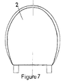
- Figure 7 shows a top view of the lid 2 which shows a bevelled peripheral edge to the lid 2.
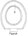
- Figure 8 shows atop view of the seat 3 showing both an inner and outer bevelled surface, the inner bevelled surface surrounding the mouth of the seat 3.
- Figure 9 represents a preferred embodiment of part of the extraction device and comprises a fan box cover 44, a fan box cover mounting 42 (FBCM) and a fan 43,
- FBCM fan box cover mounting 42
- the fan box cover 44 is substantially square in shape and is so sized as to cover substantially exactly, a standard sized bathroom or toilet tile, so that when fitted to the interior wall 41 of the bathroom or toilet, it remains substantially "flush” with the overall decor of any tiling that may be present as only one complete tile needs to be removed and replaced with the fan box cover 44.
- the FBCM 42 is a hollow substantially square tube in use provided with a shoulder running along the entire inner periphery of the tube that the fan 43 sits in, when in use.
- the occurrence of the shoulder is substantially parallel with the exterior terminal edge of the FBCM 42, (which contacts the interior wall 41 of the bathroom or toilet in use)
- the interior terminal edge of the FBCM 42 occurs at a point beyond that of the exterior terminal edge and as illustrated, this inner edge in use sits within a predrilled aperture in the wall 41 of the toilet or bathroom.
- PVC PolyVinylChloride
- the PVC sleeve then terminates at substantially the exterior face of the wall 41 of the bathroom or toilet where it is fitted with a permanently reticulated screen or otherwise "louvered" wall vent.
- the aperture in the wall 41 being so sized and shaped as to be substantially equal to the outer diameter of the PVC sleeve, in effect, ensuring that the exterior surface of the PVC sleeve contacts the aperture of the wall 41 again, in a substantially friction-push-fit type arrangement
- PVC sleeving is used in preference to any other plastics or non-plastics sleeving as it has extremely good insulation properties and it tends to minimise condensation and damp ingress wherever it is used in this manner.
- the hollow portion of the FBCM tube 42 creates an essentially static "air-pocket" within the hollow that surrounds the fan 43 when the apparatus is in use and this hollow portion is designed for a purpose.
- This hollow portion serves as a housing to hide much of the electronic wiring 45 associated with the fan 43, the wiring 45 sitting extremely neatly within this hollow.
- the hollow portion also serves the purpose of reducing the noise level of the fan 43 when in operation as air, trapped in this manner (by the hollow) is a very good noise insulator.
- the hollow also serves the additional purpose of hiding any possible interior edge fractures of the wall 41 once an aperture has been drilled through it, provided of course that the fracture is not greater than the distance "X" shown in the lower drawing of Figure 9.
- the upper drawing in Figure 9 shows the sloping portion of the fan box cover 44 to be a circular cone in shape.
- the slope of the cone with respect to the mouth 46 of the fan box cover 44 is substantially 45°. This is purposely designed so that minimal air turbulence occurs as vented odours enter the fan box cover through the mouth 46. Any such turbulence would serve to restrict the through put of air through the fan 43 It has been found by experimentation that the angle of 45° minimises any air turbulence, ensuring that the through put of air through the fan 43 once the apparatus is installed and in operation, is at least 10 litres of air per second (the reader is referred to the OEM results at the end of this specification - Appendix 1).
- the fan box cover 44 is made from Acrylonitrile Butadiene Styrene ABS, as it has been found that this particular plastics material has one of the best sound absorbing properties of any plastics material in the market place. Furthermore, it lends itself extremely well to the application of paint which "takes” to this form of plastics material extremely well.
- the fan box cover 44 is fitted to the FBCM 42 through the use of conventional "arrow-clips" 47.
- Figure 10 illustrates the means of linking the toilet seat 1 to the fan box cover 44 in use which is through some piping 48, the outer diameter of which, at both its proximal (that end nearest the toilet seat 1) and its distal (that end nearest the fan box cover 44) end is such that they respectively slide into one end of the hinge 4 and into the mouth 46 of the fan box cover 44 in a friction-push-fit type arrangement.
- This piping 48 forms the remaining essential part of the extraction device and in this particular embodiment is also made from ABS.
- the fan 43 or "air mover” is model No FN12B3, manufactured by Comair Rotron (see Appendix 1) and is, in this context, therefore, an "off the shelf” item (as opposed to the fan box cover 44 and FBCM 42).
- the fan 43 was chosen for its quality, long life, low voltage, safety records, low maintenance and quiet operation and provides more than adequate airflow tests as conducted by "OEM Automatic” (see Appendix 1).
- the fan 43 in use, is operated or actuated by a passive infrared (PIR) sensor 62.
- PIR passive infrared
- the PIR sensor 62 is again, an “off the shelf” item. In fact, it is the “Reflex” PIR sensor 62 manufactured and sold by "Texecom", a trading style of "Texecom Limited".
- the requirements of the PIR sensor 62 for its use as part of this apparatus are as follows:
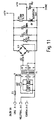
- Figure 11 is a circuit diagram of a power supply suitable for use in the extraction device.
- a 240V ac input is transformed, rectified and smoothed to provide de outputs of+12V and +5V.
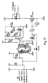
- Figure 12 is a circuit diagram of the control circuitry for fan 43.
- inputs A and B are provided by a passive infrared sensor 62 and the timer is set up to provide an operating voltage at outputs J4-1 and J4-2 to fan 43 for fifteen minutes. Other operating periods may be pre-set
- the passive infrared sensor 62 may be envisaged instead of the passive infrared sensor 62, for example an input signal from an ultrasonic sensor or a conventional light switch.
- location of the sensor is obviously important.
- the sensor 62 may be located in the vicinity of the bathroom door so as to be actuated on entry of someone into the room or alternatively, the sensor 62 may be located in the immediate vicinity of the toilet itself.
- Figure 13 shows the compact layout of the electronic components of the power supply and fan control circuitry on a PCB.
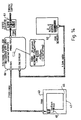
- the PCB of Figure 13 is contained within electronic control box 60 as shown in Figure 14.
- a mains input is supplied to the power supply described above via a fused isolator 61.
- the input transducer (in this case PIR sensor 62) is also input to electronic control box 60 for connection with the PCB contained therein.
- the output of electronic control box 60 is via a two-core cable to fan 43.
- the fan 43 is provided with sufficient operating power from the electronic control box 60 for a specified period of time after actuation by the PIR sensor 62.
- the period of fan operation may be adjusted via an external control on the electronic control box 60; in this embodiment a 20 second "test” setting may be selected or a 15 minutes "normal” setting.
- the hinge aperture 10 could be provided with a mesh that is so sized and shaped as to prevent, for example, a small child's fingers being inserted into the aperture 10 thereby preventing damage to the fingers the lid 2 is suddenly raised.
- the size of the aperture 10 could be larger than the aperture of 11 of the tube 7 such that the aperture 11 when the seat 3 is lowered is completely surrounded by the aperture 10.
- the head of the lid 2 could be flush with the head of the top side of the seat 3.
- the lid 2 in its entirety could in principle, flush with the entire outer peripheral edge of the upper surface of the seat 3.
- the tube 7 will be fitted to some form of extraction device which will come into operation once the seat 3 is lowered. A current of air through the mouth of the under side of the seat 3 across the under side of the mouth of the seat 3 through apertures 10 and 11 via the pathway "B" will then ensure that no noxious odours escape the toilet bowl 50 when the toilet seat 1 is in use.
- the extraction device is operated via the light switch in the toilet or bathroom, when the seat 3 is in its raised position, a problem may occur with the extraction device if one end of the tube 7 is sealed. In other words, there will be no pathway "B" available to the extraction device and as a result, this may put the extraction device under undue "stress" and may damage the system. Therefore, in an alternative embodiment (not illustrated) the sealed end of the tube 7 could be provided with a valve that comes into operation if the seat is raised and the extraction device is on allowing a passage of air through the tube 7, thereby not damaging the extraction device if it is on.
- the extraction device may be operated by for example, an infra red beam
- the hinge aperture 10 could be opened or closed via a sliding door or press fit attachment or hinge fitted attachment.
- the pathway "B" could be generated not via a rotary motion of the seat 3 but a linear motion of the tube 7 across the hinge along the longitudinal axis of the hinge 4.
- the tube 7 could be made to rotate about the longitudinal axis of the hinge form, via for example, a hand attachment that extends beyond the hinge 4 and hinge block 5 to generate the pathway "B".
- OEM Automatic were approached in confidence by Ventalu in January of 1997 to supply an air mover for use with a vented toilet seat to draw dry air across the lower half of the seat thus preventing unwanted smells from dissipating into the room.
- the air mover was to reside in a separate unit (fan box) that is linked to the seat assembly by 1.25" pipe and in-turn vents to free air through an external wall.
- a Comair Rotron FLIGHT II90 FE12B3-031168 12 Vdc, 92mm 2 axial fan was selected as the air mover.
- Nicholas Porter Divisional manager
- Kevin Simpson Sales Engineer
- the tests were conducted using a Cambridge AccuSense ATM-24 (multi-channel airflow and temperature monitor) and CAFS-220 sensors (airflow and air temperature sensors) feeding results into a conventional laptop computer running MS EXCEL TM in WINDOWS 95 TM.
- CAFS-220 sensors were positioned at the rectangular inlet orifice of the toilet seat, one on the left and one on the right. The airflow readings were then averaged.
- One CAFS-220 sensor was positioned at the outlet of the fan box where the fan exhausts into free air.
- the ATM-24 and CAFS-220 sensors record linear velocity of air and not mass flow.
- the relationship between the two is simply that of Cross Sectional Area (CSA).
- CSA Cross Sectional Area
- the CSA of the 1.25" (840mm 2 ) pipe was the main restriction to airflow and was therefore used in mass flow calculations.
- the chosen unit of mass flow was Litres per Second (l/sec).
- Linear velocity reading was in Millimetres per Second (mm/sec).
- 1/sec [(mm/sec x CSA) /1,000,000]
- the selected fan is designed for continuous duty life of 60,000 hours (6.85 years) at 25 Degrees C. The fan only being run periodically will increase its life prorata.
- the fan is constructed to the highest possible standards by an ISO9001 manufacturer and conforms to EMI standards per FCC Part 15, Subpart J of Docket 20780, Class A or B radiated and conducted emissions. Also designed to meet EMI standards per VDE Specification 0871/6 78 for category A and B requirements. Both FCC and VDE class B standards relate to use in domestic applications.
Landscapes
- Health & Medical Sciences (AREA)
- Public Health (AREA)
- Epidemiology (AREA)
- Life Sciences & Earth Sciences (AREA)
- Engineering & Computer Science (AREA)
- Hydrology & Water Resources (AREA)
- Water Supply & Treatment (AREA)
- Toilet Supplies (AREA)
- Bidet-Like Cleaning Device And Other Flush Toilet Accessories (AREA)
Abstract
Description
- The invention relates to odour venting apparatus for a toilet, in particular, but not exclusively to domestic toilets, in particular, but not exclusively to the path of airflow across the apparatus when in use.
- There have been many attempts in the past to develop a device capable of efficiently and repeatedly extracting odours from toilets that is easy to install, maintain and clean. In fact, this type of invention has occupied the minds of so-called "arm-chair" inventors and the serious industrial manufacturer for decades. The patent literature bears testimony to this fact, yet few, if any devices have entered the market place. Of the few that have, one such device is shown and illustrated in UK patent application GB-A- 2 266 901. In this particular patent specification, air is removed from within the toilet bowl via apertures located in the underside of the seat itself, which connect to form a hollow air channel within the seat. The problem with such a device, is that of air replacement. As air is removed from the rim of the toilet bowl and into the apertures of the hollow seat, the extracted air will be replaced by incoming air following a "path of least resistance". In this case, such a path will be through the front underside of the seat (and then, primarily into, the first two apertures nearest the front of the seat). Therefore, further air extraction where it is most needed, i.e towards the rear of the seat, although possible, is likely to be minimal. Of the remaining published patent literature on this topic, only two other specifications are of particular relevance to this patent application. They are US-A- 1,794,635 and US-A- 3,916,459.
- US patent number US-A-1 794 635, to all intents and purposes shows a similar arrangement to GB-A-2 266 901 with a series of apertures forming a hollow channel around the sides of the underside of the seat.
- US patent number US-A- 3,916,459 on the other hand, shows an apparatus for venting the toilet bowl of noxious odours that includes a conduit formed within the toilet seat, interconnecting the toilet bowl chamber and an opening in the toilet seat axle.
- According to the present invention in its broadest aspect, there is provided a toilet seat as defined in
claim 1. - Preferably, the closure means comprises an apertured tube substantially concentric with the hinge, the hinge being capable of movement between first and second positions, in the first position both the aperture of the hinge and the aperture of the tube overlap to some degree and in the second position no such overlap occurs.
- Preferably, the hinge and seat are so linked that movement of the hinge between first and second positions results from a rotary motion about the axis of the hinge caused by the raising and lowering of the seat
- The underside of the seat comprises two independent substantially continuous lips that underlie the seat, each of which terminate at the head of the seat, each lip being so designed to substantially overlie the top of the bowl in a contiguous relationship and to contact or otherwise mate with that portion of the hinge that secures the toilet seat to the bowl.
- More preferably still, the head of the seat is recessed to allow ease of raising and lowering of the lid.
- Optionally, the hinge-incorporated aperture is substantially centrally located.
- Preferably, the toilet seat incorporates an extraction device capable of "sucking" odours through the aperture and venting them away from the vicinity of the toilet seat once said extraction device has been actuated.
- The extraction device comprises a housing fitted with an air mover, a power supply and control circuitry for the air mover, connection means connecting the housing to the toilet seat and preferably part of the housing in use, is provided with an essentially static "air-pocket" which surrounds the air mover.
- Preferably, a portion of the housing is cone shaped, the slope of the cone being in the range of 40 - 50° with respect to the mouth of the housing.
- Preferably, the external size of the housing has substantially the dimensions of a standard 6-inch bathroom tile.
- Preferably, at least some of the visible parts of the extraction device in use are made from Acrylonitrile Butadiene Styrene
- Preferably, the extraction device further comprises a sleeve which in use, is generally concentric with and adjacent the air mover.
- Preferably, the sleeve is made from Poly Vinyl Chloride.
- Preferably, the sleeve terminates in a reticulated wall vent.
- Preferably the extraction device is actuated by disruption of an infrared beam i.e. the control circuitry receives an input from an infrared sensor.
- Preferably, the seat is solid in cross-section.
- Preferably, the invention also includes within its scope a toilet bowl incorporating a toilet seat as specified above.
- Preferred embodiments of the invention will now be more particularly described. by way of example only, with reference to the accompanying sheets of drawings wherein:
- Figure 1 illustrates a cross-sectional view of one embodiment of the present invention showing the seat in its lowered position and its raised position and the effect this has on the resulting aperture "B".
- Figure 2 illustrates a perspective view of the
apertured tube 7 together with a cross-sectional view along the line "D:D" together with a cross-sectional view of theapertured hinge region 4 andhinge block 5. - Figure 3 illustrates a cross-sectional view of the
seat 3 with a "cut-away" section "A" showing a preferred location of thehinge aperture 10. - Figure 4 illustrates a plan view of the underside of the
seat 3. - Figure 5 illustrates a side view of the toilet seat.
- Figure 6 is a plan view of the underside ofthe
lid 2. - Figure 7 is a plan view of the top of the
lid 2. - Figure 8 is a plan view of the top of the
seat 3 - Figure 9 illustrates respectively a top view of the fan box cover and a cross-section schematic view of the fan box cover, fan box cover mounting and fan.
- Figure 10 illustrates perspective views of part of the toilet seat and extraction device for venting odours from a toilet fully installed with the lid closed and open.
- Figure 11 is a circuit diagram of a power supply suitable for use in the extraction device.
- Figure 12 is a circuit diagram of the fan control circuitry.
- Figure 13 is a plan view of the printed circuit board on which the power supply and fan control circuitry are mounted.
- Figure 13A shows part of Figure 13 to an enlarged scale.
- Figure 14 is a schematic diagram of the extraction device.
-
- Throughout this specification, the use of the word "integral" is intended to cover not only something which is formed from the outset as one single-entity component but also anything which, whilst being assembled from a plurality of initially disparately-produced integers, ends up as one overall and normally non-dismantleable structure.
- For the avoidance of doubt, the term "toilet seat" is intended to cover the
lid 2 thehinge 4 and hingeblock 5 andseat 3. - Figure 1 shows the toilet seat, generally referenced I in a raised and lowered position respectively. The
toilet seat 1 comprises alid 2, aseat 3 and ahinge 4. Thehinge 4 is integral with thehinge block 5, the latter, in use, being used to secure thetoilet seat 1 to thetoilet bowl 50 via conventional "nut and bolt" or other fixing means, (again not illustrated) - The
seat 3 is provided with twoindependent lips 6 integral with the under side of theseat 3. - The
hinge 4 is substantially cylindrical and is apertured. Theseat 3 is integral with that part of thehinge 4 that is apertured and lifting theseat 3 as can be seen clearly in Figure 1 alters the position of the hinge aperture (in other words, rotating theseat 3 about the longitudinal axis of the hinge 4). It will also be noted that the apertured portion of thehinge 4 that is integral with theseat 3 is also free to rotate about thehinge block 5 in a conventional manner. - For the avoidance of doubt, the
hinge 4 essentially comprises three components, an inner portion that is integral with theseat 3 and is apertured, that is free to rotate about the longitudinal axis of thehinge 4 and two outer nonapertured components 36 that are also free to rotate about the longitudinal axis of thehinge 4 and are integral with thelid 2. - From the diagrams in Figure 1, it will also be noted that the
lips 6 are adapted to "mate" with the hingedblock 5 in the lowered position. - Along the length of the
hinge 4, and concentric with it, there is to be found an innercylindrical tube 7. Thetube 7 is permanently fixed or secured in position via conventional fixing means such as glue or welds but it will also be noted that thetube 7 is apertured. In alternative embodiments, thetube 7 may be demountable and fitted into place with for example, a grub screw. The size of the aperture is larger than the hinge aperture but as can clearly be seen in Figure 1, when theseat 3 is in the lowered position, the hinge aperture is wholly enclosed by the tube aperture providing a pathway denoted by the letter "B". - Figure 1 also illustrates the seat in a raised position and as can be seen, once the seat is raised, the hinge aperture is completely out of phase with the tube aperture closing the pathway denoted by the letter "B".
- Figure 2 illustrates the
tube 7 in a perspective view and it shows thetube aperture 10 centrally located in the wall of the tube. Figure 2 also illustrates the central portion of the hinge 4 (i.e., that part of the hinge that is integral with the seat 3) together with thehinge block 5 in cross section. Also illustrated in Figure 2 is a cross sectional view along the line DD of thetube 7. It will be noted that theaperture 10 is larger than theaperture 11. - Figure 3 illustrates another perspective view of the
seat 3 in cross section but this time seen from the "front" of theseat 3. For the sake of clarity, a further portion of theseat 3 has been removed and this is the portion denoted by the letter "A" between the "squiggly lines". This clearly illustrates the fact that thehinge aperture 10 is centrally located on the under side of theseat 3, a straight line drawn from the top of theaperture 10 to the bottom of theaperture 10 would bisect the top of theseat 3 at an angle of between 40° and 60° to the vertical In other words, the plane of the mouth of theaperture 10 bisects theseat 3 between the angles specified above. In this particular embodiment, the angle is 45°. - The under
side 6 of theseat 3 is also provided with a resilientlyflexible material 14 that extends slightly beyond the plane of theunder side 6 of theseat 3 and is designed to overlie the top surface of the toilet bowl (not illustrated) when theseat 3 is lowered. The weight of an individual sat on theseat 3 will force the resilientlyflexible material 14 into a temporary substantially "air-tight" seal around the top surface of the toilet bowl (not illustrated). - Figure 4 shows the
seat 3 viewed from the under side clearly illustrating the location of thelips 6 and resilientlyflexible material 14 - As can be see in Figure 4, the under side of the seat comprises two
continuous lips 6 that underlie the seat, each of which terminate at the "head" of the under side of theseat 3. As a result of the resilientlyflexible material 14 and the mating action of thelips 6 with thehinge block 5, when an individual sits on theseat 3, substantially, the only means of air-flow across the under side of theseat 3 is through the "mouth" of the "head" of the under side of theseat 3. - Figure 5 shows the
toilet seat 1 replete withlid 2,seat 3,hinge 4 and hingeblock 5, thelid 2 being in the "closed" position It will be noted that thelid 2 is provided with tworubber teats 8 so positioned to come in contact with either side of the top surface of theseat 3 so that thelid 2 does not mar or chip the top surface of theseat 3 if thelid 2 is inadvertently "dropped" down on to theseat 3 It will also be noted that the clearance between thelid 2 and theseat 3 as a result of theteats 8 is less than 1 cm and in this embodiment is approximately 5 mm. Thelid 2 is also provided with arecess 9 at its head to enable an individual to lift thelid 2 with ease by inserting one's fingers under therecess 9. Although not clearly illustrated, the head of thelid 2 passes beyond the mouth of theseat 3 so that when "looking-down" on thelid 2 in Figure 5, the mouth of theseat 3 cannot be seen at all. - Figure 6 shows a plan view of the under side of the
lid 2 of thetoilet seat 1 and also shows theouter hinge portions 36 which are integral with theseat 3,hinge 4 and hingeblock 5 once thetoilet seat 1 is assembled. The location of theteats 8 are also clearly illustrated together with the broad depth of therecess 9. - Figure 7 shows a top view of the
lid 2 which shows a bevelled peripheral edge to thelid 2. - Figure 8 shows atop view of the
seat 3 showing both an inner and outer bevelled surface, the inner bevelled surface surrounding the mouth of theseat 3. - Turning now to the rest of the odour venting apparatus, Figure 9 represents a preferred embodiment of part of the extraction device and comprises a
fan box cover 44, a fan box cover mounting 42 (FBCM) and afan 43, - The
fan box cover 44 is substantially square in shape and is so sized as to cover substantially exactly, a standard sized bathroom or toilet tile, so that when fitted to theinterior wall 41 of the bathroom or toilet, it remains substantially "flush" with the overall decor of any tiling that may be present as only one complete tile needs to be removed and replaced with thefan box cover 44. - As can be seen from the lower drawing of Figure 9, the
FBCM 42 is a hollow substantially square tube in use provided with a shoulder running along the entire inner periphery of the tube that thefan 43 sits in, when in use. The occurrence of the shoulder is substantially parallel with the exterior terminal edge of theFBCM 42, (which contacts theinterior wall 41 of the bathroom or toilet in use) The interior terminal edge of theFBCM 42 occurs at a point beyond that of the exterior terminal edge and as illustrated, this inner edge in use sits within a predrilled aperture in thewall 41 of the toilet or bathroom. The entire portion of theFBCM 42 that sits within the aperture, in use, acts as a receiving member for a PolyVinylChloride (PVC) sleeve (not illustrated) that grips the exterior face of this inner portion in a friction-push-fit type arrangement in use. - The PVC sleeve then terminates at substantially the exterior face of the
wall 41 of the bathroom or toilet where it is fitted with a permanently reticulated screen or otherwise "louvered" wall vent. The aperture in thewall 41 being so sized and shaped as to be substantially equal to the outer diameter of the PVC sleeve, in effect, ensuring that the exterior surface of the PVC sleeve contacts the aperture of thewall 41 again, in a substantially friction-push-fit type arrangement PVC sleeving is used in preference to any other plastics or non-plastics sleeving as it has extremely good insulation properties and it tends to minimise condensation and damp ingress wherever it is used in this manner. - The hollow portion of the FBCM tube 42 (created once the
FBCM 42 has been fitted into place against theinterior wall 41 of the bathroom or toilet) creates an essentially static "air-pocket" within the hollow that surrounds thefan 43 when the apparatus is in use and this hollow portion is designed for a purpose. One such purpose is that this hollow portion serves as a housing to hide much of theelectronic wiring 45 associated with thefan 43, thewiring 45 sitting extremely neatly within this hollow. The hollow portion also serves the purpose of reducing the noise level of thefan 43 when in operation as air, trapped in this manner (by the hollow) is a very good noise insulator. The hollow also serves the additional purpose of hiding any possible interior edge fractures of thewall 41 once an aperture has been drilled through it, provided of course that the fracture is not greater than the distance "X" shown in the lower drawing of Figure 9. - Turning now to the
fan box cover 44, the upper drawing in Figure 9 shows the sloping portion of thefan box cover 44 to be a circular cone in shape. The slope of the cone with respect to themouth 46 of thefan box cover 44 is substantially 45°. This is purposely designed so that minimal air turbulence occurs as vented odours enter the fan box cover through themouth 46. Any such turbulence would serve to restrict the through put of air through thefan 43 It has been found by experimentation that the angle of 45° minimises any air turbulence, ensuring that the through put of air through thefan 43 once the apparatus is installed and in operation, is at least 10 litres of air per second (the reader is referred to the OEM results at the end of this specification - Appendix 1). - The
fan box cover 44 is made from Acrylonitrile Butadiene Styrene ABS, as it has been found that this particular plastics material has one of the best sound absorbing properties of any plastics material in the market place. Furthermore, it lends itself extremely well to the application of paint which "takes" to this form of plastics material extremely well. Thefan box cover 44, is fitted to theFBCM 42 through the use of conventional "arrow-clips" 47. - Figure 10 illustrates the means of linking the
toilet seat 1 to thefan box cover 44 in use which is through some piping 48, the outer diameter of which, at both its proximal (that end nearest the toilet seat 1) and its distal (that end nearest the fan box cover 44) end is such that they respectively slide into one end of thehinge 4 and into themouth 46 of thefan box cover 44 in a friction-push-fit type arrangement. This piping 48 forms the remaining essential part of the extraction device and in this particular embodiment is also made from ABS. - With respect to the distal end of the piping 48 being fined into the
mouth 46 of thefan box cover 44, this has the positive advantage that should thefan 43 require cleaning on a periodic basis; then thefan box cover 44 can be "pulled" free of the face of theinterior wall 41 without the need to dismantle the whole of the piping 48 from thetoilet seat 1 Thefan box cover 44 will simply slide over the piping 48 allowing access to thefan 43 enabling it to be cleaned. - The
fan 43 or "air mover" is model No FN12B3, manufactured by Comair Rotron (see Appendix 1) and is, in this context, therefore, an "off the shelf" item (as opposed to thefan box cover 44 and FBCM 42). Thefan 43 was chosen for its quality, long life, low voltage, safety records, low maintenance and quiet operation and provides more than adequate airflow tests as conducted by "OEM Automatic" (see Appendix 1). - The
fan 43, in use, is operated or actuated by a passive infrared (PIR)sensor 62. ThePIR sensor 62 is again, an "off the shelf" item. In fact, it is the "Reflex"PIR sensor 62 manufactured and sold by "Texecom", a trading style of "Texecom Limited". The requirements of thePIR sensor 62 for its use as part of this apparatus are as follows: - 1) Versatile mounting positions - wall, ceiling or corner.
- 2) Variable mounting heights, (up to 4.1 metres).
- 3) Variable range of operation (up to 33 metres)
- 4) Fast, slow or normal speed operation of detection
- 5) Variable angle and degree of coverage.
- 6) Low voltage and safe.
-
- "The Reflex" possesses all of these requirements and a number of others and the reader is now positively directed towards document reference R/EU/3.0 produced by Texecom Limited (copyright 1994) which details further aspects of the "Reflex" specification.
- Figure 11 is a circuit diagram of a power supply suitable for use in the extraction device. A 240V ac input is transformed, rectified and smoothed to provide de outputs of+12V and +5V.
- Figure 12 is a circuit diagram of the control circuitry for
fan 43. In this particular case, inputs A and B are provided by a passiveinfrared sensor 62 and the timer is set up to provide an operating voltage at outputs J4-1 and J4-2 to fan 43 for fifteen minutes. Other operating periods may be pre-set - Other types of input transducer may be envisaged instead of the passive
infrared sensor 62, for example an input signal from an ultrasonic sensor or a conventional light switch. In this preferred embodiment, using a passiveinfrared sensor 62, location of the sensor is obviously important. For example, thesensor 62 may be located in the vicinity of the bathroom door so as to be actuated on entry of someone into the room or alternatively, thesensor 62 may be located in the immediate vicinity of the toilet itself. - Figure 13 shows the compact layout of the electronic components of the power supply and fan control circuitry on a PCB.
- In use, the PCB of Figure 13 is contained within
electronic control box 60 as shown in Figure 14. A mains input is supplied to the power supply described above via a fused isolator 61. The input transducer (in this case PIR sensor 62) is also input toelectronic control box 60 for connection with the PCB contained therein. The output ofelectronic control box 60 is via a two-core cable tofan 43. - In use, the
fan 43 is provided with sufficient operating power from theelectronic control box 60 for a specified period of time after actuation by thePIR sensor 62. The period of fan operation may be adjusted via an external control on theelectronic control box 60; in this embodiment a 20 second "test" setting may be selected or a 15 minutes "normal" setting. - The embodiment illustrated in the Figures are by way of example only and alternative embodiments can be envisaged without departing from the scope of the invention and these will now be described.
- For example, the
hinge aperture 10 could be provided with a mesh that is so sized and shaped as to prevent, for example, a small child's fingers being inserted into theaperture 10 thereby preventing damage to the fingers thelid 2 is suddenly raised. Alternatively, the size of theaperture 10 could be larger than the aperture of 11 of thetube 7 such that theaperture 11 when theseat 3 is lowered is completely surrounded by theaperture 10. Alternatively, when theseat 3 is lowered, there may be advantages in having only a partial phasing of theapertures - In yet another alternative embodiment, the head of the
lid 2 could be flush with the head of the top side of theseat 3. In fact, thelid 2 in its entirety, could in principle, flush with the entire outer peripheral edge of the upper surface of theseat 3. - The
tube 7 will be fitted to some form of extraction device which will come into operation once theseat 3 is lowered. A current of air through the mouth of the under side of theseat 3 across the under side of the mouth of theseat 3 throughapertures toilet bowl 50 when thetoilet seat 1 is in use. - If for example, the extraction device is operated via the light switch in the toilet or bathroom, when the
seat 3 is in its raised position, a problem may occur with the extraction device if one end of thetube 7 is sealed. In other words, there will be no pathway "B" available to the extraction device and as a result, this may put the extraction device under undue "stress" and may damage the system. Therefore, in an alternative embodiment (not illustrated) the sealed end of thetube 7 could be provided with a valve that comes into operation if the seat is raised and the extraction device is on allowing a passage of air through thetube 7, thereby not damaging the extraction device if it is on. The extraction device may be operated by for example, an infra red beam - Finally, the
hinge aperture 10 could be opened or closed via a sliding door or press fit attachment or hinge fitted attachment. Alternatively, the pathway "B" could be generated not via a rotary motion of theseat 3 but a linear motion of thetube 7 across the hinge along the longitudinal axis of thehinge 4. Alternatively, thetube 7 could be made to rotate about the longitudinal axis of the hinge form, via for example, a hand attachment that extends beyond thehinge 4 and hingeblock 5 to generate the pathway "B". - OEM Automatic were approached in confidence by Ventalu in January of 1997 to supply an air mover for use with a vented toilet seat to draw dry air across the lower half of the seat thus preventing unwanted smells from dissipating into the room. The air mover was to reside in a separate unit (fan box) that is linked to the seat assembly by 1.25" pipe and in-turn vents to free air through an external wall. After careful consideration and some preliminary experimentation a Comair Rotron FLIGHT II90 FE12B3-031168 12 Vdc, 92mm2 axial fan was selected as the air mover. On April 25th Nicholas Porter (Divisional manager) and Kevin Simpson (Sales Engineer) of OEM Automatic conducted the following secret tests in validation of choice of fan.
- The tests were conducted in a dry room at ambient room temperature and at sea level. Present were Nicholas Porter, Kevin Simpson and John Reynolds of Ventalu.
- The tests were conducted using a Cambridge AccuSense ATM-24 (multi-channel airflow and temperature monitor) and CAFS-220 sensors (airflow and air temperature sensors) feeding results into a conventional laptop computer running MS EXCEL TM in WINDOWS 95 TM.
- Two CAFS-220 sensors were positioned at the rectangular inlet orifice of the toilet seat, one on the left and one on the right. The airflow readings were then averaged. One CAFS-220 sensor was positioned at the outlet of the fan box where the fan exhausts into free air.
- The fan box and the toilet seat assembly were connected via various lengths of 1.25" plastic pipe (CSA = 840mm2). All seals were inspected to be free of leaks and the pipe free of restrictions. The fan box exhausted to free air. Experimentation was conducted by varying the pipe lengths and introducing right-angled bends.
- The ATM-24 and CAFS-220 sensors record linear velocity of air and not mass flow. The relationship between the two is simply that of Cross Sectional Area (CSA). The CSA of the 1.25" (840mm2) pipe was the main restriction to airflow and was therefore used in mass flow calculations. The chosen unit of mass flow was Litres per Second (l/sec). Linear velocity reading was in Millimetres per Second (mm/sec). To convert from linear velocity to mass flow the following formula was used:
- Results are tabulated as below:
Straight Length (mm) Flow Inlet (l/sec) Flow Outlet (l/sec) 300 16.2 4.8 600 15.3 4.8 2,000 12.9 4.0 2,600 12.3 4.0 One right-angled bend Length (mm) Flow Inlet (l/sec) Flow Outlet (l/sec) 300 16.2 4.8 600 15.1 4.4 2,000 11.9 4.0 2,600 12.0 4,0 Two right-angled bends Length (mm) Flow Inlet (l/sec) Flow Outlet (l/sec) 3,000 11.3 4.4 4,000 10.7 4.4 - The results can be interpreted that at the worst extreme (4m pipe with two right-angled bends) that an airflow in excess of the minimum 10 l/sec threshold was still achieved. It is therefore my conclusion that the Comair Rotron FLIGHT II 90 FE12B3-031168 axial fan is wholly suitable for this application within the aforementioned test parameters. Throughout the tests the fan performed within its published operating region as expected
- The selected fan is designed for continuous duty life of 60,000 hours (6.85 years) at 25 Degrees C. The fan only being run periodically will increase its life prorata. The fan is constructed to the highest possible standards by an ISO9001 manufacturer and conforms to EMI standards per
FCC Part 15, Subpart J of Docket 20780, Class A or B radiated and conducted emissions. Also designed to meet EMI standards per VDE Specification 0871/6 78 for category A and B requirements. Both FCC and VDE class B standards relate to use in domestic applications. -
Stock Number Description Quantity Ref. C VL201A VENTALU PCB ASSY 1 1 P 67460.2 *PCB VENTALU 1 P 07200.2 ZEND BZX85C5V1 1.3W D041 D1 1 2 P 06600 DIED 1N4148 HI-SPD SGNL D2-5 4 3 P 10311 330R CF 0.5W 5% R1 1 4 P 11543 5K1 MF 0.5W 1% MFR4 # R2 1 6 P 11880 510K MF 0.5W 1% MFR4 # R3 1 7 P 11612 22K MF 0.5W 1% MFR4 # R4,6 2 8 P 14990 ZERO OHM LINK LK1 1 10 P 10750 10K CF 0.25W 5% R5 1 9 P 10500 IK CF 0.25W 5% R7 1 11 P 15902 VARISTOR V39ZAl 25V Y1 (DEVICE MARKING 39Z1) 1 12 P 58985 3300u 20% 25V ELECT7.5mm C1 1 13 P 54554 100n 50v CERM 2.5mm C2, 3, 6 3 14 P 58160 10u 20% 16V ELECT 2mm C4 1 16 P 58972.5 2200U 20% 16V ELECT 5mm C5 1 17 P 00561.1 IC MM74HC123AN DIP 16 U1 1 18 P 06329 TRAN ZTX614 U2 1 19 P 07043.5 BR RECTIFIER W02 1.5A U3 1 21 P 30862 FUSEHOLDER 20mm PCB MNT F1 1 22 P 30875 FUSEHOLDER 20mm PCB MNT F2 1 20 P 31495 FUSE 20mm 200mA Q/BL FIT TO F1 (FIT AT TEST) 1 23 P 31593 FUSE 20mm 400mA (T) A/S FIT TO F2 (FIT AT TEST) 1 25 P 21198.4 3W TERM BLK 2.5mm ENTRY J1 1 24 P 30270.1 36W PCB PIN HDR S.ROW J2 CUT TO LENGTH REQD 0.084 26 P 30450 2W JUMPER LINKCLOSED FIT TO J2 1 27 P 21204 4W TERM BLK 2.5mm ENTRY J3 1 28 P 21198.2 2W TERMBLK 2.5mm ENTRY J4 1 29 P 61930 TXFMR MAINS 6VA 9-0-9 # T1 1 31 80270.1 *BOX DRILLED FOR VL202A 1 2 P 80270 #BOX ABS 150x80x50mm GY DRILL BOX TO DRG 1 1 P 95715 CABLE 2W 7/28AWG TWST PR 4 3 P 93995 CABLE 3W 16/0.2 MAINS WH 3 4 P 95820 CABLE 4W 7/0.2mm WH 4 6 P 65330 SUPPORT PCB ¼" HIGH 5 7 P 93565 BUSH CABLE STRAIN RELIEF 2 8 P 93570 BUSH CABLE STRAIN RELIEF 1 9 P 30650 H/SHRINK ADH LINED 9mm 1 11 P NOTES For comments only 0 12
Claims (8)
- A toilet seat (1) adapted to extract odours for use with a conventional toilet bowl (50) and an odour extraction device (42-47), the toilet seat (1) comprising:their in-use arrangement being such that the toilet seat (1) can be fitted to a conventional toilet bowl (50) in a manner generally known per se, the lid (2) and seat (3) then being integral with and able to rotate about the hinge (4), again in a manner generally known per se, and wherein the hinge region (4,5,36) incorporates an aperture (10,11) through which odours from the bowl (50) can pass, the aperture (10,11) being fitted with or encompassing closure means (7), and the interaction between the various elements being such that the aperture (10,11) is open when the seat (3) is lowered and is closed when the seat (3) is raised, and wherein the extraction device (42-47), once the device (42-47) is actuated, draws odours through the aperture (10,11) and vents them away from the vicinity of the toilet seat (1), characterised in that the underside of the seat (3) comprises two independent lips (6), the shaping of which and their interaction with the closure means (7) when the seat (3) is in its said lowered position are such that together they direct the under-the-seat-air-flow from the front of the toilet bowl (50) toward the rear of the toilet bowl (50) whilst constraining substantially the whole of the air-flow to follow that front-to-rear-path by travelling across the central region of the toilet bowl (50) as it travels towards and ultimately into the aperture (10, 11).i) a lid (2);ii) a seat (3) ;iii) a hinge (4) ;
- A toilet seat (1) as claimed in claim 1 characterised in that the underside of each lip (6) of the seat (3) is provided with a resiliently flexible material (14) that extends slightly beyond the plane of the underside of each lip (6), the material (14) being designed to overlie the top surface of a toilet bowl (50) when the seat (3) is lowered.
- A toilet seat (1) as claimed in claim 1 or claim 2 characterised in that the aperture (10,11) is provided with a mesh that is so sized and shaped as to prevent, in particular, a small child's fingers being inserted into the aperture (10,11) thereby preventing damage to the fingers when the lid (2) is suddenly raised.
- A toilet seat as claimed in any of the preceding claims and further comprising an extraction device (42-47) capable of "sucking" odours through the aperture (10,11) and venting them away from the vicinity of the toilet seat (1) once said extraction device (42-47) has been actuated, the extraction device (42-47) comprising a housing (42,44) fitted with an air mover (43), and characterised in that part of the housing (42) in use, is provided with an essentially static "air pocket" which surrounds the air mover (43).
- A toilet seat (1) as claimed in claim 4 characterised in that the external size (44) of the housing (42,44) has substantially the dimensions of a standard 15.24 cm (6 inch) bathroom tile.
- A toilet seat (1) as claimed in claim 4 or claim 5 characterised in that at least some of the visible components of the extraction device (42-47) in use are made from acrylonitrile butadiene styrene.
- A toilet seat (1) as claimed in any of claims 4-6 characterised in that the extraction device (42-47) further comprises a Poly Vinyl Chloride sleeve which, in use, is generally concentric with and adjacent the air mover (43).
- A toilet bowl (50) incorporating a toilet seat (1) as claimed in any of the preceding claims.
Applications Claiming Priority (3)
| Application Number | Priority Date | Filing Date | Title |
|---|---|---|---|
| GB9622971 | 1996-11-05 | ||
| GBGB9622971.1A GB9622971D0 (en) | 1996-11-05 | 1996-11-05 | Improvements in and relating to odour venting apparatus for a toilet |
| PCT/GB1997/003012 WO1998019586A1 (en) | 1996-11-05 | 1997-11-03 | Improvements in and relating to odour venting apparatus for a toilet |
Publications (2)
| Publication Number | Publication Date |
|---|---|
| EP0948280A1 EP0948280A1 (en) | 1999-10-13 |
| EP0948280B1 true EP0948280B1 (en) | 2002-04-17 |
Family
ID=10802430
Family Applications (1)
| Application Number | Title | Priority Date | Filing Date |
|---|---|---|---|
| EP97910560A Expired - Lifetime EP0948280B1 (en) | 1996-11-05 | 1997-11-03 | A toilet seat adapted to extract odours |
Country Status (6)
| Country | Link |
|---|---|
| EP (1) | EP0948280B1 (en) |
| AT (1) | ATE216209T1 (en) |
| AU (1) | AU4790497A (en) |
| DE (1) | DE69712098T2 (en) |
| GB (2) | GB9622971D0 (en) |
| WO (1) | WO1998019586A1 (en) |
Cited By (1)
| Publication number | Priority date | Publication date | Assignee | Title |
|---|---|---|---|---|
| DE102011101106A1 (en) | 2011-05-10 | 2012-11-15 | Alexander Schluttig | Aerosol-tight closure for toilet bowl used in e.g. hospital, has gasket that is provided between toilet cover and seat ring |
Families Citing this family (6)
| Publication number | Priority date | Publication date | Assignee | Title |
|---|---|---|---|---|
| PL332986A1 (en) * | 1999-05-06 | 2000-11-20 | Jung Eugeniusz | Method of extracting intestinal gas from a lavatory bowl and apparatus therefor |
| AU714333B3 (en) | 1999-06-18 | 1999-12-23 | Michael Gerard Siddle | Improvements in the ventilation of toilets |
| GB0107347D0 (en) * | 2001-03-23 | 2001-05-16 | Mckirdy Thomas | Vented toilet seat |
| FR2854181B1 (en) * | 2003-04-22 | 2006-02-03 | Ramez Ghadri | TOILET ODOR VACUUM SUPPLIED BY A RECHARGEABLE BATTERY AND / OR SOLAR CELLS |
| DE102004062165B4 (en) * | 2004-12-20 | 2009-12-24 | Daniel Stephan | Means for sitting on a toilet bowl and simultaneously venting the toilet bowl |
| JP6478174B1 (en) * | 2017-12-28 | 2019-03-06 | Toto株式会社 | Toilet lid device |
Family Cites Families (12)
| Publication number | Priority date | Publication date | Assignee | Title |
|---|---|---|---|---|
| GB191328170A (en) * | 1913-12-06 | 1914-04-23 | George Edgar Hughes | Improvements relating to the Ventilation of the Bowls or Pans of Water Closets. |
| US1794635A (en) * | 1929-11-13 | 1931-03-03 | William W Mills | Ventilating device |
| US2190068A (en) * | 1938-05-13 | 1940-02-13 | Henschler Ewald | Lavatory device |
| US2279870A (en) * | 1940-06-07 | 1942-04-14 | David V Johnson | Ventilation of water closet bowls and seats |
| GB860212A (en) * | 1958-07-07 | 1961-02-01 | Walter Whitehorn | Improvements in ventilating apparatus for sanitary closets |
| US3916459A (en) * | 1974-04-19 | 1975-11-04 | Marko Ivancevic | Toilet ventilating apparatus in kit form |
| US4125906A (en) * | 1977-03-17 | 1978-11-21 | Weiland George G | Toilet ventilating apparatus |
| GB2143872A (en) * | 1983-07-26 | 1985-02-20 | John Headley Billing | Ventilating W.C. pans |
| GB2247255B (en) * | 1990-08-22 | 1994-04-13 | Enzo Casale | Lavatory pan seat |
| JPH04303198A (en) * | 1991-03-29 | 1992-10-27 | Toshiba Corp | Cross flow fan |
| GB2266901B (en) * | 1992-05-14 | 1995-08-23 | Enzo Casale | Lavatory seat ventilation assembly |
| GB9416822D0 (en) * | 1994-08-19 | 1994-10-12 | Thompson Robert J | Toilet |
-
1996
- 1996-11-05 GB GBGB9622971.1A patent/GB9622971D0/en active Pending
-
1997
- 1997-11-03 EP EP97910560A patent/EP0948280B1/en not_active Expired - Lifetime
- 1997-11-03 AU AU47904/97A patent/AU4790497A/en not_active Abandoned
- 1997-11-03 DE DE69712098T patent/DE69712098T2/en not_active Expired - Fee Related
- 1997-11-03 GB GB9723204A patent/GB2320936B/en not_active Expired - Fee Related
- 1997-11-03 AT AT97910560T patent/ATE216209T1/en not_active IP Right Cessation
- 1997-11-03 WO PCT/GB1997/003012 patent/WO1998019586A1/en not_active Ceased
Cited By (1)
| Publication number | Priority date | Publication date | Assignee | Title |
|---|---|---|---|---|
| DE102011101106A1 (en) | 2011-05-10 | 2012-11-15 | Alexander Schluttig | Aerosol-tight closure for toilet bowl used in e.g. hospital, has gasket that is provided between toilet cover and seat ring |
Also Published As
| Publication number | Publication date |
|---|---|
| GB9723204D0 (en) | 1998-01-07 |
| EP0948280A1 (en) | 1999-10-13 |
| GB9622971D0 (en) | 1997-01-08 |
| DE69712098T2 (en) | 2002-11-28 |
| DE69712098D1 (en) | 2002-05-23 |
| AU4790497A (en) | 1998-05-29 |
| ATE216209T1 (en) | 2002-05-15 |
| WO1998019586A1 (en) | 1998-05-14 |
| GB2320936B (en) | 2000-10-11 |
| GB2320936A (en) | 1998-07-08 |
Similar Documents
| Publication | Publication Date | Title |
|---|---|---|
| US5386594A (en) | Toilet ventilating manifold system | |
| US7632178B2 (en) | Ventilation blower controls employing air quality sensors | |
| EP3179000B1 (en) | Toilet bowl venting system | |
| US7823227B2 (en) | Bathroom odor removal apparatus and system | |
| US4829882A (en) | Crawl space ventilation system | |
| CN105627450A (en) | Window type air purifier | |
| EP0948280A1 (en) | Improvements in and relating to odour venting apparatus for a toilet | |
| US6363542B1 (en) | Toilet ventilator | |
| US20140090160A1 (en) | Odor Removing Toilet | |
| US5947814A (en) | Garage CO venting system | |
| WO1991010101A1 (en) | Pressure controlled fresh air supply ventilation system using soil gas pressure as a reference, and method of use | |
| YU49487B (en) | DRYING DEVICE | |
| US20060200897A1 (en) | System for extracting odors | |
| US20050028255A1 (en) | Toilet bowl with ventilating system | |
| GB2327095A (en) | Toilet odour removal apparatus | |
| US20040083541A1 (en) | Odorless Toilet | |
| KR102390500B1 (en) | Electric damper integrated hood cap | |
| KR200208398Y1 (en) | Gas leak detection device | |
| FR2741807A1 (en) | Plug-in fan diffuser for perfume, deodorant or insecticide | |
| KR100488298B1 (en) | Toilet seat ventilating apparatus | |
| US20080256693A1 (en) | Systems and Apparatus for Toilet Odour Removal | |
| EP3145380B1 (en) | Toilet ventilation system | |
| JP2005139618A (en) | Toilet equipment | |
| KR20180052149A (en) | Ventilating system for kitchen | |
| CN106638857A (en) | Bathroom ventilating system |
Legal Events
| Date | Code | Title | Description |
|---|---|---|---|
| PUAI | Public reference made under article 153(3) epc to a published international application that has entered the european phase |
Free format text: ORIGINAL CODE: 0009012 |
|
| 17P | Request for examination filed |
Effective date: 19990607 |
|
| AK | Designated contracting states |
Kind code of ref document: A1 Designated state(s): AT BE CH DE DK ES FI FR GB GR IE IT LI LU MC NL PT SE |
|
| 17Q | First examination report despatched |
Effective date: 20000627 |
|
| RTI1 | Title (correction) |
Free format text: A TOILET SEAT ADAPTED TO EXTRACT ODOURS |
|
| GRAG | Despatch of communication of intention to grant |
Free format text: ORIGINAL CODE: EPIDOS AGRA |
|
| GRAG | Despatch of communication of intention to grant |
Free format text: ORIGINAL CODE: EPIDOS AGRA |
|
| GRAH | Despatch of communication of intention to grant a patent |
Free format text: ORIGINAL CODE: EPIDOS IGRA |
|
| REG | Reference to a national code |
Ref country code: GB Ref legal event code: IF02 |
|
| GRAH | Despatch of communication of intention to grant a patent |
Free format text: ORIGINAL CODE: EPIDOS IGRA |
|
| GRAA | (expected) grant |
Free format text: ORIGINAL CODE: 0009210 |
|
| AK | Designated contracting states |
Kind code of ref document: B1 Designated state(s): AT BE CH DE DK ES FI FR GB GR IE IT LI LU MC NL PT SE |
|
| PG25 | Lapsed in a contracting state [announced via postgrant information from national office to epo] |
Ref country code: NL Free format text: LAPSE BECAUSE OF FAILURE TO SUBMIT A TRANSLATION OF THE DESCRIPTION OR TO PAY THE FEE WITHIN THE PRESCRIBED TIME-LIMIT Effective date: 20020417 Ref country code: LI Free format text: LAPSE BECAUSE OF FAILURE TO SUBMIT A TRANSLATION OF THE DESCRIPTION OR TO PAY THE FEE WITHIN THE PRESCRIBED TIME-LIMIT Effective date: 20020417 Ref country code: IT Free format text: LAPSE BECAUSE OF FAILURE TO SUBMIT A TRANSLATION OF THE DESCRIPTION OR TO PAY THE FEE WITHIN THE PRE;WARNING: LAPSES OF ITALIAN PATENTS WITH EFFECTIVE DATE BEFORE 2007 MAY HAVE OCCURRED AT ANY TIME BEFORE 2007. THE CORRECT EFFECTIVE DATE MAY BE DIFFERENT FROM THE ONE RECORDED.SCRIBED TIME-LIMIT Effective date: 20020417 Ref country code: GR Free format text: LAPSE BECAUSE OF FAILURE TO SUBMIT A TRANSLATION OF THE DESCRIPTION OR TO PAY THE FEE WITHIN THE PRESCRIBED TIME-LIMIT Effective date: 20020417 Ref country code: FI Free format text: LAPSE BECAUSE OF FAILURE TO SUBMIT A TRANSLATION OF THE DESCRIPTION OR TO PAY THE FEE WITHIN THE PRESCRIBED TIME-LIMIT Effective date: 20020417 Ref country code: CH Free format text: LAPSE BECAUSE OF FAILURE TO SUBMIT A TRANSLATION OF THE DESCRIPTION OR TO PAY THE FEE WITHIN THE PRESCRIBED TIME-LIMIT Effective date: 20020417 Ref country code: BE Free format text: LAPSE BECAUSE OF FAILURE TO SUBMIT A TRANSLATION OF THE DESCRIPTION OR TO PAY THE FEE WITHIN THE PRESCRIBED TIME-LIMIT Effective date: 20020417 Ref country code: AT Free format text: LAPSE BECAUSE OF FAILURE TO SUBMIT A TRANSLATION OF THE DESCRIPTION OR TO PAY THE FEE WITHIN THE PRESCRIBED TIME-LIMIT Effective date: 20020417 |
|
| REF | Corresponds to: |
Ref document number: 216209 Country of ref document: AT Date of ref document: 20020515 Kind code of ref document: T |
|
| REG | Reference to a national code |
Ref country code: CH Ref legal event code: EP |
|
| REG | Reference to a national code |
Ref country code: IE Ref legal event code: FG4D |
|
| REF | Corresponds to: |
Ref document number: 69712098 Country of ref document: DE Date of ref document: 20020523 |
|
| PG25 | Lapsed in a contracting state [announced via postgrant information from national office to epo] |
Ref country code: SE Free format text: LAPSE BECAUSE OF FAILURE TO SUBMIT A TRANSLATION OF THE DESCRIPTION OR TO PAY THE FEE WITHIN THE PRESCRIBED TIME-LIMIT Effective date: 20020717 Ref country code: PT Free format text: LAPSE BECAUSE OF FAILURE TO SUBMIT A TRANSLATION OF THE DESCRIPTION OR TO PAY THE FEE WITHIN THE PRESCRIBED TIME-LIMIT Effective date: 20020717 Ref country code: DK Free format text: LAPSE BECAUSE OF FAILURE TO SUBMIT A TRANSLATION OF THE DESCRIPTION OR TO PAY THE FEE WITHIN THE PRESCRIBED TIME-LIMIT Effective date: 20020717 |
|
| NLV1 | Nl: lapsed or annulled due to failure to fulfill the requirements of art. 29p and 29m of the patents act | ||
| ET | Fr: translation filed | ||
| PG25 | Lapsed in a contracting state [announced via postgrant information from national office to epo] |
Ref country code: ES Free format text: LAPSE BECAUSE OF FAILURE TO SUBMIT A TRANSLATION OF THE DESCRIPTION OR TO PAY THE FEE WITHIN THE PRESCRIBED TIME-LIMIT Effective date: 20021030 |
|
| REG | Reference to a national code |
Ref country code: CH Ref legal event code: PL |
|
| PG25 | Lapsed in a contracting state [announced via postgrant information from national office to epo] |
Ref country code: LU Free format text: LAPSE BECAUSE OF NON-PAYMENT OF DUE FEES Effective date: 20021103 |
|
| PG25 | Lapsed in a contracting state [announced via postgrant information from national office to epo] |
Ref country code: IE Free format text: LAPSE BECAUSE OF NON-PAYMENT OF DUE FEES Effective date: 20021104 |
|
| PLBE | No opposition filed within time limit |
Free format text: ORIGINAL CODE: 0009261 |
|
| STAA | Information on the status of an ep patent application or granted ep patent |
Free format text: STATUS: NO OPPOSITION FILED WITHIN TIME LIMIT |
|
| 26N | No opposition filed |
Effective date: 20030120 |
|
| PG25 | Lapsed in a contracting state [announced via postgrant information from national office to epo] |
Ref country code: MC Free format text: LAPSE BECAUSE OF NON-PAYMENT OF DUE FEES Effective date: 20030601 |
|
| REG | Reference to a national code |
Ref country code: IE Ref legal event code: MM4A |
|
| PGFP | Annual fee paid to national office [announced via postgrant information from national office to epo] |
Ref country code: DE Payment date: 20051124 Year of fee payment: 9 |
|
| PGFP | Annual fee paid to national office [announced via postgrant information from national office to epo] |
Ref country code: FR Payment date: 20051128 Year of fee payment: 9 |
|
| PG25 | Lapsed in a contracting state [announced via postgrant information from national office to epo] |
Ref country code: DE Free format text: LAPSE BECAUSE OF NON-PAYMENT OF DUE FEES Effective date: 20070601 |
|
| REG | Reference to a national code |
Ref country code: FR Ref legal event code: ST Effective date: 20070731 |
|
| PG25 | Lapsed in a contracting state [announced via postgrant information from national office to epo] |
Ref country code: FR Free format text: LAPSE BECAUSE OF NON-PAYMENT OF DUE FEES Effective date: 20061130 |
|
| PGFP | Annual fee paid to national office [announced via postgrant information from national office to epo] |
Ref country code: GB Payment date: 20071220 Year of fee payment: 11 |
|
| GBPC | Gb: european patent ceased through non-payment of renewal fee |
Effective date: 20081103 |
|
| PG25 | Lapsed in a contracting state [announced via postgrant information from national office to epo] |
Ref country code: GB Free format text: LAPSE BECAUSE OF NON-PAYMENT OF DUE FEES Effective date: 20081103 |