EP0948121A2 - Load side filter arrangement for a power converter circuit - Google Patents
Load side filter arrangement for a power converter circuit Download PDFInfo
- Publication number
- EP0948121A2 EP0948121A2 EP99810218A EP99810218A EP0948121A2 EP 0948121 A2 EP0948121 A2 EP 0948121A2 EP 99810218 A EP99810218 A EP 99810218A EP 99810218 A EP99810218 A EP 99810218A EP 0948121 A2 EP0948121 A2 EP 0948121A2
- Authority
- EP
- European Patent Office
- Prior art keywords
- capacitor
- filter arrangement
- converter circuit
- load
- capacitors
- Prior art date
- Legal status (The legal status is an assumption and is not a legal conclusion. Google has not performed a legal analysis and makes no representation as to the accuracy of the status listed.)
- Granted
Links
Images
Classifications
-
- H—ELECTRICITY
- H02—GENERATION; CONVERSION OR DISTRIBUTION OF ELECTRIC POWER
- H02M—APPARATUS FOR CONVERSION BETWEEN AC AND AC, BETWEEN AC AND DC, OR BETWEEN DC AND DC, AND FOR USE WITH MAINS OR SIMILAR POWER SUPPLY SYSTEMS; CONVERSION OF DC OR AC INPUT POWER INTO SURGE OUTPUT POWER; CONTROL OR REGULATION THEREOF
- H02M1/00—Details of apparatus for conversion
- H02M1/12—Arrangements for reducing harmonics from ac input or output
- H02M1/126—Arrangements for reducing harmonics from ac input or output using passive filters
Definitions
- the invention relates to the field of power electronics. It goes out from a load-side filter arrangement for a converter circuit arrangement according to the preamble of the first claim.
- a generic filter arrangement is already in European patent applications EP 0 682 401 A1 and EP 0 682 402 A2.
- the object of the present invention is to provide a filter arrangement for a Specify converter circuitry in which the destructive Consequences of a capacitor short circuit are reduced to a minimum or entirely can be avoided.
- the short-circuit current is limited and there are no common-mode voltages on the motor.
- Standard resistors can be used as the earth resistance. Even with several capacitor groups connected in parallel, depending on the energy content of the capacitor groups, only one earth resistance is required.
- the capacitor groups are preferably each enclosed by a filter can.
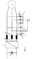
- FIG. 1 shows an embodiment of the invention.
- 1 is a power electronic Circuit arrangement, in particular an inverter, referred to that of a DC voltage intermediate circuit, represented by the intermediate circuit capacitor Czk and the plus and minus pole +/-, is fed.
- the inverter 1 converts the DC voltage into an AC voltage more variable Amplitude and frequency around.
- This AC voltage feeds a load to For example a motor M.
- a load-side filter is provided, which is between the load connections 4 of the inverter 1 and the load M is switched.
- the filter essentially comprises an LC element with a series inductance 2 and one per phase Capacitor 3.
- the capacitors 3 there are now two capacitors 3 per phase provided and one each is assigned to one of the two capacitor groups 5 and 6.
- the two capacitor groups 5 and 6 consequently each comprise three capacitors, which e.g. kept immersed in oil and preferably surrounded by a jug.
- the capacitors 3 one Capacitor groups are connected in a star. It is the essence of the invention well, the capacitors of one capacitor group are hard, i.e. without interposing of a ground resistance and those of the other capacitor group to be grounded with high resistance via a grounding resistor 7.
Landscapes
- Engineering & Computer Science (AREA)
- Power Engineering (AREA)
- Inverter Devices (AREA)
- Power Conversion In General (AREA)
- Dc-Dc Converters (AREA)
- Networks Using Active Elements (AREA)
Abstract
Description
Die Erfindung bezieht sich auf das Gebiet der Leistungselektronik. Sie geht aus von einer lastseitigen Filteranordnung für eine Stromrichterschaltungsanordnung gemäss dem Oberbegriff des ersten Anspruchs. Eine gattungsgemässe Filteranordnung ist schon in den Europäischen Patentanmeldungen EP 0 682 401 A1 und EP 0 682 402 A2 beschrieben.The invention relates to the field of power electronics. It goes out from a load-side filter arrangement for a converter circuit arrangement according to the preamble of the first claim. A generic filter arrangement is already in European patent applications EP 0 682 401 A1 and EP 0 682 402 A2.
In den obengenannten Schriften ist ein allenfalls mittels Widerständen verlustbehafteter LC-Tiefpass zwischen die Lastanschlüsse und eine Last eingefügt. Die Anschlüsse der Kondensatoren können entweder zu einem Sternpunkt zusammengeführt werden oder mit dem Plus- bzw. Minusanschluss des Zwischenkreises verbunden sein. Die in diesen Schriften gezeigten Schaltungsanordnungen werden vorzugsweise für Niederspannungsanwendungen eingesetzt. Aus der EP 0 318 790 ist zudem ein Hochpass einer Filteranordnung für eine mit Stromrichtern verbundene Leitung bekannt.In the above-mentioned documents there is a lossy one at most by means of resistors LC low pass inserted between the load connections and a load. The connections of the capacitors can either be brought together to a star point or with the plus or minus connection of the DC link be connected. The circuit arrangements shown in these documents are mainly used for low voltage applications. Out EP 0 318 790 is also a high pass filter arrangement for a Converters connected line known.
Ziel eines lastseitigen Filters ist es, eine möglichst sinusförmige Ausgangsspannung zu erzielen. Ein Weg wäre nun, das Filter möglichst gross auszulegen. Dies bringt jedoch einige gewichtige Nachteile mit sich: Bei einem Kurzschluss des Filterkondensators entlädt sich der betroffene und alle parallelgeschalteten Kondensatoren in den Kurzschluss. Ausserdem können durch den Kurzschluss grosse Drehmomentsprünge am angeschlossenen Motor und hohe Überspannungen an den Motorwicklungen und Filterkondensatoren auftreten. Als Folgefehler können weitere Kurzschlüsse auftreten, so dass eine grosse Energie schlagartig frei wird, was Zerstörungen nach sich ziehen kann. Je grösser die Filterkapazität gewählt wird, desto grösser ist die Energie, die in einer defekten Filterkanne vernichtet werden muss. Dadurch kann die Filterkanne zerplatzen, Isolationsöl kann austreten und die Umwelt verschmutzen.The goal of a load-side filter is to achieve an output voltage that is as sinusoidal as possible to achieve. One way would be to design the filter as large as possible. This However, there are some major disadvantages: If the Filter capacitor discharges the affected and all connected in parallel Capacitors in the short circuit. In addition, the short circuit large torque jumps on the connected motor and high overvoltages occur on the motor windings and filter capacitors. As a consequential error further short circuits can occur, so that a large energy suddenly becomes free, which can lead to destruction. The bigger the Filter capacity is chosen, the greater the energy involved in a broken Filter can must be destroyed. This can cause the filter can to burst, Insulation oil can leak and pollute the environment.
Aufgabe der vorliegenden Erfindung ist es, eine Filteranordnung für eine Stromrichterschaltungsanordnung anzugeben, bei welcher die zerstörerischen Folgen eines Kondensatorkurzschlusses auf ein Minimum begrenzt bzw. ganz vermieden werden können.The object of the present invention is to provide a filter arrangement for a Specify converter circuitry in which the destructive Consequences of a capacitor short circuit are reduced to a minimum or entirely can be avoided.
Diese Aufgabe wird bei einer n-phasigen Stromrichterschaltungsanordnung der eingangs genannten Art durch die Merkmale des ersten Anspruchs gelöst.This object is achieved in the case of an n-phase converter circuit arrangement initially mentioned type solved by the features of the first claim.
Kern der Erfindung ist es also, die Kondensatoren des lastseitigen Filters in mindestens zwei n-phasige Kondensatorgruppen zusammenzufassen und die eine Kondensatorgruppe hart und die andere hochohmig über einen Erdungswiderstand zu erden. Bei einem Kurzschluss einer Filterkapazität fällt dadurch nur die Kapazität der defekte Kondensatorgruppe weg. Die anderen Kondensatoren sehen weiterhin die normale Phasenspannung und entladen sich somit solange 1 / ω·C f << Re (Cf = Filterkapazität, Re = Erdungswiderstand) nicht Ausserdem treten nach dem Kondensatorkurzschluss keine Überspannungen auf, und der Motor bzw. die Last erfährt ebenfalls keine Überspannungen. Ein Weiterbetrieb der Anlage nach dem Kurzschluss ist grundsätzlich möglich. Gleiches gilt für einen einphasigen Motorerdschluss. Bei motorseitigem Erd- und Klemmenkurzschluss wird der Kurzschlussstrom begrenzt, und es treten keine Gleichtakt-Spannungen am Motor auf. Als Erdungswiderstand können Standardwiderstände eingesetzt werden. Auch bei mehreren parallelgeschalteten Kondensatorgruppen ist je nach Energieinhalt der Kondensatorgruppen nur ein Erdungswiderstand nötig. Vorzugsweise werden die Kondensatorgruppen jeweils von einer Filterkanne umschlossen.The essence of the invention is therefore to combine the capacitors of the load-side filter into at least two n-phase capacitor groups and to ground one capacitor group hard and the other high-resistance via an earth resistance. If a filter capacitance is short-circuited, only the capacitance of the defective capacitor group is lost. The other capacitors continue to see the normal phase voltage and therefore do not discharge as long as 1 / ω · C f << R e (Cf = filter capacitance, Re = earth resistance). Furthermore, no overvoltages occur after the capacitor short circuit, and the motor or the load experiences also no overvoltages. It is generally possible to continue operating the system after the short circuit. The same applies to a single-phase motor earth fault. In the event of an earth and terminal short-circuit on the motor side, the short-circuit current is limited and there are no common-mode voltages on the motor. Standard resistors can be used as the earth resistance. Even with several capacitor groups connected in parallel, depending on the energy content of the capacitor groups, only one earth resistance is required. The capacitor groups are preferably each enclosed by a filter can.
Nachfolgend wird die Erfindung anhand von Ausführungsbeispielen im Zusammenhang mit den Zeichnungen näher erläutert.In the following, the invention is described in connection with exemplary embodiments explained in more detail with the drawings.
Es zeigen:
- Fig. 1
- Ein Ausführungsbeispiel des erfindungsgemässen Schaltungsaufbaus.
- Fig. 1
- An embodiment of the circuit construction according to the invention.
Die in den Zeichnungen verwendeten Bezugszeichen und deren Bedeutung sind in der Bezugszeichenliste zusammengefasst aufgelistet. Grundsätzlich sind in den Figuren gleiche Teile mit gleichen Bezugszeichen versehen. The reference numerals used in the drawings and their meaning are summarized in the list of reference symbols. Basically are in the same parts with the same reference numerals.
Figur 1 zeigt ein Ausführungsbeispiel der Erfindung. Mit 1 ist eine leistungselektronische
Schaltungsanordnung, insbesondere ein Wechselrichter, bezeichnet,
der von einem Gleichspannungszwischenkreis, dargestellt durch den Zwischenkreiskondensator
Czk und den Plus- und Minuspol +/-, gespeist wird. Der Wechselrichter
1 wandelt die Gleichspannung in eine Wechselspannung variabler
Amplitude und Frequenz um. Diese Wechselspannung speist eine Last, zum
Beispiel einen Motor M. Damit möglichst sinusförmige Ausgangsgrössen erreicht
werden, ist ein lastseitiges Filter vorgesehen, das zwischen die Lastanschlüsse 4
des Wechselrichters 1 und die Last M geschaltet ist. Das Filter umfasst im wesentlichen
eine LC-Glied mit pro Phase einer Serieinduktivität 2 und einem
Kondensator 3. Nach der Erfindung sind nun pro Phase zwei Kondensatoren 3
vorgesehen und je einer ist einer der beiden Kondensatorgruppen 5 und 6 zugeordnet.
Allgemein werden somit für eine n-phasige Schaltung mindestens zwei
n-phasige Kondensatorgruppen gebildet. Die beiden Kondensatorgruppen 5 und
6 umfassen folglich je drei Kondensatoren, die z.B. in Öl getaucht gehalten und
vorzugsweise von einer Kanne umschlossen werden. Die Kondensatoren 3 einer
Kondensatorgruppe sind jeweils in Stern geschaltet. Kern der Erfindung ist es
nun, die Kondensatoren der einen Kondensatorgruppe hart, d.h. ohne Zwischenschalten
eines Erdungswiderstandes und diejenigen der anderen Kondensatorgruppe
hochohmig über einen Erdungswiderstand 7 zu erden. Figure 1 shows an embodiment of the invention. With 1 is a power electronic
Circuit arrangement, in particular an inverter, referred to
that of a DC voltage intermediate circuit, represented by the intermediate circuit capacitor
Czk and the plus and minus pole +/-, is fed. The
- 11
- StromrichterschaltungsanordnungPower converter circuitry
- 22nd
- SerieinduktivitätSeries inductance
- 33rd
- Kondensatorcapacitor
- 44th
- LastanschlussLoad connection
- 55
- erste Kondensatorgruppefirst capacitor group
- 66
- zweite Kondensatorgruppesecond capacitor group
- CzkCzk
- ZwischenkreiskondensatorDC link capacitor
- MM
- Motor, LastEngine, load
- ++
- PlusanschlussPositive connection
- --
- MinusanschlussMinus connection
Claims (2)
Applications Claiming Priority (2)
| Application Number | Priority Date | Filing Date | Title |
|---|---|---|---|
| DE19814059A DE19814059A1 (en) | 1998-03-30 | 1998-03-30 | Load-side filter arrangement for a converter circuit arrangement |
| DE19814059 | 1998-03-30 |
Publications (3)
| Publication Number | Publication Date |
|---|---|
| EP0948121A2 true EP0948121A2 (en) | 1999-10-06 |
| EP0948121A3 EP0948121A3 (en) | 2000-03-15 |
| EP0948121B1 EP0948121B1 (en) | 2004-10-27 |
Family
ID=7862885
Family Applications (1)
| Application Number | Title | Priority Date | Filing Date |
|---|---|---|---|
| EP99810218A Expired - Lifetime EP0948121B1 (en) | 1998-03-30 | 1999-03-11 | Load side filter arrangement for a power converter circuit |
Country Status (5)
| Country | Link |
|---|---|
| US (1) | US6160442A (en) |
| EP (1) | EP0948121B1 (en) |
| KR (1) | KR100546430B1 (en) |
| CA (1) | CA2266941C (en) |
| DE (2) | DE19814059A1 (en) |
Cited By (1)
| Publication number | Priority date | Publication date | Assignee | Title |
|---|---|---|---|---|
| EP2162976B1 (en) * | 2007-01-22 | 2016-08-17 | Johnson Controls Technology Company | Common mode & differential mode filter for variable speed drive |
Families Citing this family (6)
| Publication number | Priority date | Publication date | Assignee | Title |
|---|---|---|---|---|
| DE19952886A1 (en) * | 1999-11-03 | 2001-05-10 | Abb Research Ltd | Multi-way current regulator e.g. for electric motor, has local earth provided for each current regulator unit coupled to common line earth via earthing impedance |
| DE102004051129A1 (en) * | 2004-10-18 | 2006-04-20 | Siemens Ag | Throttle, in particular for operation in a frequency converter system, and frequency converter system |
| GB2508442A (en) * | 2012-11-29 | 2014-06-04 | Control Tech Ltd | Conducted emissions filter |
| KR101596335B1 (en) | 2014-06-24 | 2016-02-22 | 주식회사 에스앤케이일렉트로닉스 | Molding machine with improved mold plate moving precision |
| KR20160000314A (en) | 2014-06-24 | 2016-01-04 | 주식회사 에스앤케이일렉트로닉스 | Molding machine with improved mold plate moving variation protecion structure |
| DE102015104660A1 (en) | 2015-03-26 | 2016-09-29 | Block Transformatoren-Elektronik Gmbh | throttle arrangement |
Citations (1)
| Publication number | Priority date | Publication date | Assignee | Title |
|---|---|---|---|---|
| EP0829948A2 (en) * | 1996-09-13 | 1998-03-18 | Asea Brown Boveri AG | Power converter device with output filter |
Family Cites Families (10)
| Publication number | Priority date | Publication date | Assignee | Title |
|---|---|---|---|---|
| GB1034341A (en) * | 1962-04-06 | 1966-06-29 | English Electric Co Ltd | Improvements in and relating to electrical filters |
| US3501686A (en) * | 1968-08-22 | 1970-03-17 | Asea Ab | Control device for a filter circuit for a static inverter |
| US3883792A (en) * | 1973-06-28 | 1975-05-13 | Gen Electric | Optimum control system for minimizing harmonic effects in HVDC power converters |
| EP0131815B1 (en) * | 1983-07-13 | 1986-09-03 | BBC Aktiengesellschaft Brown, Boveri & Cie. | Ac motor drive |
| DE3334817A1 (en) * | 1983-09-26 | 1985-04-04 | Siemens AG, 1000 Berlin und 8000 München | Arrangement of a number of electrical low-pass filters |
| JPH0834694B2 (en) * | 1986-10-25 | 1996-03-29 | 株式会社日立製作所 | Control device for power converter |
| DE3869344D1 (en) * | 1987-12-04 | 1992-04-23 | Siemens Ag | HIGH-PASS OF A FILTER ARRANGEMENT FOR A LINE CONNECTED WITH RECTIFIERS. |
| CH693524A5 (en) * | 1994-05-11 | 2003-09-15 | Schaffner Emv Ag | Means for limiting the Aenderungsgeschwindigkeit the output values of a self-commutated via a DC intermediate circuit polyphase inverter. |
| CH693523A5 (en) * | 1994-05-11 | 2003-09-15 | Schaffner Emv Ag | Means for limiting the Aenderungsgeschwindigkeit the output-side voltage of a self-commutated multiphase converter. |
| DE29800567U1 (en) * | 1998-01-14 | 1998-04-09 | Siemens AG, 80333 München | Damping filter arrangement for converters with regulated voltage intermediate circuit and sinusoidal phase currents |
-
1998
- 1998-03-30 DE DE19814059A patent/DE19814059A1/en not_active Withdrawn
-
1999
- 1999-03-11 DE DE59910926T patent/DE59910926D1/en not_active Expired - Lifetime
- 1999-03-11 EP EP99810218A patent/EP0948121B1/en not_active Expired - Lifetime
- 1999-03-24 CA CA002266941A patent/CA2266941C/en not_active Expired - Fee Related
- 1999-03-24 KR KR1019990010118A patent/KR100546430B1/en not_active IP Right Cessation
- 1999-03-30 US US09/280,986 patent/US6160442A/en not_active Expired - Lifetime
Patent Citations (1)
| Publication number | Priority date | Publication date | Assignee | Title |
|---|---|---|---|---|
| EP0829948A2 (en) * | 1996-09-13 | 1998-03-18 | Asea Brown Boveri AG | Power converter device with output filter |
Non-Patent Citations (1)
| Title |
|---|
| KIM S -J ET AL: "A NOVEL FILTR DESIGN FOR SUPPRESSION OF HIGH VOLTAGE GRADIENT IN VOLTAGE-FED PWM INVERTER" APEC. ANNUAL APPLIED POWER ELECTRONICS CONFERENCE AND EXPOSITION,US,NEW YORK, IEEE, Bd. CONF. 12, 1997, Seiten 122-127, XP000736180 ISBN: 0-7803-3705-0 * |
Cited By (1)
| Publication number | Priority date | Publication date | Assignee | Title |
|---|---|---|---|---|
| EP2162976B1 (en) * | 2007-01-22 | 2016-08-17 | Johnson Controls Technology Company | Common mode & differential mode filter for variable speed drive |
Also Published As
| Publication number | Publication date |
|---|---|
| KR19990078226A (en) | 1999-10-25 |
| DE19814059A1 (en) | 1999-10-07 |
| KR100546430B1 (en) | 2006-01-26 |
| CA2266941A1 (en) | 1999-09-30 |
| EP0948121A3 (en) | 2000-03-15 |
| EP0948121B1 (en) | 2004-10-27 |
| US6160442A (en) | 2000-12-12 |
| CA2266941C (en) | 2008-06-17 |
| DE59910926D1 (en) | 2004-12-02 |
Similar Documents
| Publication | Publication Date | Title |
|---|---|---|
| EP1040555B1 (en) | Converter connection assembly with a direct voltage intermediate circuit | |
| EP0899859B1 (en) | Intermediate voltage link inverter | |
| EP1695434B1 (en) | Converter circuit with two partial converters | |
| EP0855758B1 (en) | Circuit for the protection of RF input circuits of telecommunication devices | |
| EP1296441B1 (en) | Power generating arrangement | |
| EP0829948B1 (en) | Power converter device with output filter | |
| EP0682402B1 (en) | Output magnitudes rise limiting device for self-commutated constant voltage intermediate circuit converter | |
| EP0948121B1 (en) | Load side filter arrangement for a power converter circuit | |
| DE10062075A1 (en) | Converter with integrated DC link capacitors | |
| EP0682401B1 (en) | Limiting device for the output voltage slope of a self-commutated converter | |
| EP0187312B1 (en) | Filter circuit | |
| EP1318594B1 (en) | Power converter circuit for increasing an AC voltage | |
| WO2006015966A1 (en) | Hv-circuit arrangement having a high electric strength of at least 10 kv and use of said arrangement | |
| DE102005036512A1 (en) | Circuit layout, e.g. to act as a voltage divider for measuring direct current voltage and alternating current voltage, has a high-voltage strength of 10 kV or more | |
| WO2018113926A1 (en) | Power converter | |
| DE102005016962A1 (en) | Arrangement with a three-phase machine and a frequency converter | |
| EP1190474B1 (en) | Controller protective device for a dual-voltage electric system | |
| EP1479558A1 (en) | Traction converter circuit for coupling to a electrical supply network | |
| WO2004105225A2 (en) | Converter circuit | |
| DE10204040A1 (en) | Method for operating an intermediate circuit voltage changer, e.g. for electric motor controller, uses phased power supply in sinusoidal operation on earthed mains system | |
| WO2020228909A1 (en) | Electric motor and drive comprising an electric motor | |
| DE102004004627A1 (en) | AC motor voltage supply is provided by circuit that reduces symmetrical and asymmetrical voltage components | |
| EP1619785A2 (en) | Converter circuit with voltage rise rate limitation | |
| DE19647933A1 (en) | Static power converter for railway traction current supply | |
| DE102009019850A1 (en) | Device for connecting electrical machine to electrical energy source by electrical cable, has two electrical power supplies and electrical cable for connection of respective power supply to electrical device |
Legal Events
| Date | Code | Title | Description |
|---|---|---|---|
| PUAI | Public reference made under article 153(3) epc to a published international application that has entered the european phase |
Free format text: ORIGINAL CODE: 0009012 |
|
| AK | Designated contracting states |
Kind code of ref document: A2 Designated state(s): DE FR GB IT |
|
| AX | Request for extension of the european patent |
Free format text: AL;LT;LV;MK;RO;SI |
|
| PUAL | Search report despatched |
Free format text: ORIGINAL CODE: 0009013 |
|
| AK | Designated contracting states |
Kind code of ref document: A3 Designated state(s): AT BE CH CY DE DK ES FI FR GB GR IE IT LI LU MC NL PT SE |
|
| AX | Request for extension of the european patent |
Free format text: AL;LT;LV;MK;RO;SI |
|
| RAP1 | Party data changed (applicant data changed or rights of an application transferred) |
Owner name: ABB INDUSTRIE AG |
|
| 17P | Request for examination filed |
Effective date: 20000816 |
|
| AKX | Designation fees paid |
Free format text: DE FR GB IT |
|
| RAP1 | Party data changed (applicant data changed or rights of an application transferred) |
Owner name: ABB SCHWEIZ AG |
|
| GRAP | Despatch of communication of intention to grant a patent |
Free format text: ORIGINAL CODE: EPIDOSNIGR1 |
|
| GRAS | Grant fee paid |
Free format text: ORIGINAL CODE: EPIDOSNIGR3 |
|
| GRAA | (expected) grant |
Free format text: ORIGINAL CODE: 0009210 |
|
| AK | Designated contracting states |
Kind code of ref document: B1 Designated state(s): DE FR GB IT |
|
| REG | Reference to a national code |
Ref country code: GB Ref legal event code: FG4D Free format text: NOT ENGLISH |
|
| REF | Corresponds to: |
Ref document number: 59910926 Country of ref document: DE Date of ref document: 20041202 Kind code of ref document: P |
|
| GBT | Gb: translation of ep patent filed (gb section 77(6)(a)/1977) |
Effective date: 20050210 |
|
| PLBE | No opposition filed within time limit |
Free format text: ORIGINAL CODE: 0009261 |
|
| STAA | Information on the status of an ep patent application or granted ep patent |
Free format text: STATUS: NO OPPOSITION FILED WITHIN TIME LIMIT |
|
| ET | Fr: translation filed | ||
| 26N | No opposition filed |
Effective date: 20050728 |
|
| REG | Reference to a national code |
Ref country code: FR Ref legal event code: PLFP Year of fee payment: 17 |
|
| PGFP | Annual fee paid to national office [announced via postgrant information from national office to epo] |
Ref country code: DE Payment date: 20150320 Year of fee payment: 17 |
|
| PGFP | Annual fee paid to national office [announced via postgrant information from national office to epo] |
Ref country code: GB Payment date: 20150319 Year of fee payment: 17 Ref country code: FR Payment date: 20150319 Year of fee payment: 17 |
|
| PGFP | Annual fee paid to national office [announced via postgrant information from national office to epo] |
Ref country code: IT Payment date: 20150330 Year of fee payment: 17 |
|
| REG | Reference to a national code |
Ref country code: DE Ref legal event code: R119 Ref document number: 59910926 Country of ref document: DE |
|
| GBPC | Gb: european patent ceased through non-payment of renewal fee |
Effective date: 20160311 |
|
| REG | Reference to a national code |
Ref country code: FR Ref legal event code: ST Effective date: 20161130 |
|
| PG25 | Lapsed in a contracting state [announced via postgrant information from national office to epo] |
Ref country code: FR Free format text: LAPSE BECAUSE OF NON-PAYMENT OF DUE FEES Effective date: 20160331 Ref country code: DE Free format text: LAPSE BECAUSE OF NON-PAYMENT OF DUE FEES Effective date: 20161001 Ref country code: GB Free format text: LAPSE BECAUSE OF NON-PAYMENT OF DUE FEES Effective date: 20160311 |
|
| PG25 | Lapsed in a contracting state [announced via postgrant information from national office to epo] |
Ref country code: IT Free format text: LAPSE BECAUSE OF NON-PAYMENT OF DUE FEES Effective date: 20160311 |