EP0948099B1 - Verbinder für Kommunikation Kabel - Google Patents
Verbinder für Kommunikation Kabel Download PDFInfo
- Publication number
- EP0948099B1 EP0948099B1 EP99302190A EP99302190A EP0948099B1 EP 0948099 B1 EP0948099 B1 EP 0948099B1 EP 99302190 A EP99302190 A EP 99302190A EP 99302190 A EP99302190 A EP 99302190A EP 0948099 B1 EP0948099 B1 EP 0948099B1
- Authority
- EP
- European Patent Office
- Prior art keywords
- conductors
- plug
- cable
- communication plug
- crosstalk
- Prior art date
- Legal status (The legal status is an assumption and is not a legal conclusion. Google has not performed a legal analysis and makes no representation as to the accuracy of the status listed.)
- Expired - Lifetime
Links
- 238000004891 communication Methods 0.000 title claims description 60
- 239000004020 conductor Substances 0.000 claims description 82
- 238000009826 distribution Methods 0.000 claims description 20
- 238000004873 anchoring Methods 0.000 claims 1
- 238000013461 design Methods 0.000 description 9
- 230000008901 benefit Effects 0.000 description 5
- 238000009413 insulation Methods 0.000 description 5
- 230000009977 dual effect Effects 0.000 description 4
- 238000000034 method Methods 0.000 description 4
- 230000000295 complement effect Effects 0.000 description 3
- 230000007246 mechanism Effects 0.000 description 3
- 239000004033 plastic Substances 0.000 description 3
- 229920003023 plastic Polymers 0.000 description 3
- 230000002238 attenuated effect Effects 0.000 description 2
- 238000004519 manufacturing process Methods 0.000 description 2
- 238000013507 mapping Methods 0.000 description 2
- 239000000463 material Substances 0.000 description 2
- 238000012986 modification Methods 0.000 description 2
- 230000004048 modification Effects 0.000 description 2
- 230000008520 organization Effects 0.000 description 2
- 230000008569 process Effects 0.000 description 2
- 230000006978 adaptation Effects 0.000 description 1
- 238000013459 approach Methods 0.000 description 1
- 239000011230 binding agent Substances 0.000 description 1
- 239000003086 colorant Substances 0.000 description 1
- 238000002788 crimping Methods 0.000 description 1
- 238000006880 cross-coupling reaction Methods 0.000 description 1
- 230000001419 dependent effect Effects 0.000 description 1
- 230000000994 depressogenic effect Effects 0.000 description 1
- 239000003989 dielectric material Substances 0.000 description 1
- 230000001939 inductive effect Effects 0.000 description 1
- 238000011900 installation process Methods 0.000 description 1
- 230000002452 interceptive effect Effects 0.000 description 1
- 238000003801 milling Methods 0.000 description 1
- 238000005457 optimization Methods 0.000 description 1
- 230000000149 penetrating effect Effects 0.000 description 1
- 239000004800 polyvinyl chloride Substances 0.000 description 1
- 230000001681 protective effect Effects 0.000 description 1
- 230000008707 rearrangement Effects 0.000 description 1
- 230000009467 reduction Effects 0.000 description 1
- 238000012552 review Methods 0.000 description 1
- 125000006850 spacer group Chemical group 0.000 description 1
Images




Classifications
-
- H—ELECTRICITY
- H01—ELECTRIC ELEMENTS
- H01R—ELECTRICALLY-CONDUCTIVE CONNECTIONS; STRUCTURAL ASSOCIATIONS OF A PLURALITY OF MUTUALLY-INSULATED ELECTRICAL CONNECTING ELEMENTS; COUPLING DEVICES; CURRENT COLLECTORS
- H01R24/00—Two-part coupling devices, or either of their cooperating parts, characterised by their overall structure
- H01R24/60—Contacts spaced along planar side wall transverse to longitudinal axis of engagement
- H01R24/62—Sliding engagements with one side only, e.g. modular jack coupling devices
- H01R24/64—Sliding engagements with one side only, e.g. modular jack coupling devices for high frequency, e.g. RJ 45
-
- H—ELECTRICITY
- H01—ELECTRIC ELEMENTS
- H01R—ELECTRICALLY-CONDUCTIVE CONNECTIONS; STRUCTURAL ASSOCIATIONS OF A PLURALITY OF MUTUALLY-INSULATED ELECTRICAL CONNECTING ELEMENTS; COUPLING DEVICES; CURRENT COLLECTORS
- H01R13/00—Details of coupling devices of the kinds covered by groups H01R12/70 or H01R24/00 - H01R33/00
- H01R13/646—Details of coupling devices of the kinds covered by groups H01R12/70 or H01R24/00 - H01R33/00 specially adapted for high-frequency, e.g. structures providing an impedance match or phase match
- H01R13/6461—Means for preventing cross-talk
-
- H—ELECTRICITY
- H01—ELECTRIC ELEMENTS
- H01R—ELECTRICALLY-CONDUCTIVE CONNECTIONS; STRUCTURAL ASSOCIATIONS OF A PLURALITY OF MUTUALLY-INSULATED ELECTRICAL CONNECTING ELEMENTS; COUPLING DEVICES; CURRENT COLLECTORS
- H01R2201/00—Connectors or connections adapted for particular applications
- H01R2201/04—Connectors or connections adapted for particular applications for network, e.g. LAN connectors
Definitions
- the present invention relates generally to the field of cable connectors and more specifically to a modular plug for terminating round cables or cordage carrying conductor pairs.
- modular plug type connectors are commonly used to connect customer premise equipment (CPE), such as telephones or computers, to a jack in another piece of CPE, such as a modem, or in a wall terminal block.
- CPE customer premise equipment
- a jack in another piece of CPE, such as a modem, or in a wall terminal block.
- These modular plugs terminate essentially two types of cable or cordage: ribbon type cables and round cables.
- the conductors running therethrough are arranged substantially in a plane and run, substantially parallel, alongside each other throughout the length of the cable.
- the individual conductors may have their own insulation or may be isolated from one another by channels defined in the jacket of the ribbon cable itself, with the ribbon jacket providing the necessary insulation.
- the conductors packaged in a standard round cable may take on a random or intended arrangement with conductors being twisted or wrapped around one another and changing relative positions throughout the cable length.
- Traditional modular plugs are well suited for terminating ribbon type cables.
- these plugs are of a dielectric, such as plastic, structure in which a set of terminals are mounted side by side in a set of troughs or channels in the plug body such that the terminals match the configuration of the conductors in the cable connected thereto.
- the terminals When the plug is inserted into a jack, the terminals will electrically engage jack springs inside the jack to complete the connection.
- termination of standard round cables or cords poses unique assembly problems for the skilled technician.
- termination of a round cable carrying, for example, four conductor pairs by means of an existing modular plug requires the following steps: First, the cable or cord jacket must be stripped to access the enclosed conductors. Next, because the conductors in a conductor pair are generally twisted around one another, the twist must be removed and the conductors oriented to align with the required interface.
- aligning the conductors also involves splitting the conductors in at least one of the pairs and routing these over or under conductors from other pairs while orienting all the conductors in a side-by-side plane. Once the conductors are aligned in a plane, they may be joined to the terminals in the plug.
- the orientation process can result in various conductors of different pairs crossing over each other, thereby inducing crosstalk among the several conductor pairs.
- Crosstalk is defined as the cross coupling of electromagnetic energy between adjacent conductor pairs in the same cable bundle or binder.
- Crosstalk can be categorized in one of two forms: Near End Crosstalk, commonly referred to as NEXT, is the most significant because the high energy signal from an adjacent conductor can induce relatively significant crosstalk into an attenuated receiver signal.
- the other form is Far End Crosstalk or FEXT.
- FEXT is typically less of an issue because the far end interfering signal is attenuated as it traverses the loop.
- FEXT Far End Crosstalk
- FEXT is typically less of an issue because the far end interfering signal is attenuated as it traverses the loop.
- the jack springs, conductors and the plug terminals or contacts near the jack springs are generally quite close to, and exposed to, one another in a communication plug, control of crosstalk is a paramount consideration in any plug design.
- crosstalk in a communication plug cannot be merely eliminated. Jacks are engineered to generate
- a modular plug that can terminate a standard round cable and that provides a straightforward interface between the conductors in the cable and the plug terminals, involving less assembly time than heretofore.
- optimization means reducing crosstalk in the plug or providing a predetermined level of crosstalk to match the requirements of a jack designed to eliminate an expected crosstalk level.
- the present invention is generally directed to a modular communication plug or connector for terminating a cable having a plurality of conductors disposed therein.
- the communication plug comprises a substantially hollow housing forming a chamber and having a conductor alignment region disposed at one end and an opening to the chamber at the other end.
- a member for orienting the conductors for reception in the alignment region is carried in the chamber.
- a crosstalk fixing member is interposed between the orienting member and the alignment region.
- a plurality of conductive terminals are disposed proximal to the alignment region for establishing electrical contact with the conductors.
- the member for orienting the conductors comprises a carrier or mandrel having a substantially planar body that segregates the conductors, typically pairwise, and terminates in a distribution end that arranges the individual conductors according to the pattern defined by the alignment region.
- the mandrel maintains the pair orientation along the length of the mandrel body until the conductors are routed into individual slots at the mandrel distribution end.
- such a carrier or mandrel can be applied as a cable termination for any jacketed cable.
- the mandrel is inserted under the cable jacket and it receives and organizes the conductors in channels formed therein to maintain a consistent routing of the conductors as they exit the end of the cable jacket.
- the mandrel maintains this organization while an anchor bar or similar strain relief mechanism is tightened over the jacket.
- the mandrel can extend beyond the end of the jacket to align the conductors according to the requirements of another termination device such as a plug carrying terminal contacts.
- the crosstalk fixing means comprises a sled component that is used to define the length of the region in which the conductors are untwisted and arranged parallel to one another. Accordingly, the skilled artisan can fix the amount of crosstalk developed in the plug by altering the length of the sled without altering the overall dimensions of the communication plug, which would require additional tooling costs. This allows the communication plug according to the present invention to work with legacy jacks that require a certain amount of complementary crosstalk to be generated in the plug for optimum performance.
- the alignment region in the communication plug housing is removed and the distribution end of the mandrel is adapted to fill the space vacated by the alignment region.
- the twist in the conductor pairs is moved as near as possible to the conductive terminals thereby minimizing the crosstalk developed in the plug. It is envisioned that this plug design will be desirable for use with future jacks that require less complementary crosstalk from the plug.
- another advantage of this embodiment is that the detailed assembly steps can be done outside of the plug housing, which allows for greater precision and reduced assembly time over prior art plug designs.
- Communication plug 20 is preferably made from a suitable dielectric (e.g., plastic) material and comprises a substantially hollow shell or housing 21 having side walls, upper and lower walls and a plurality of slots formed in one end thereof for holding a plurality of electrical terminals or contacts 22.
- Electrical terminals 22 are used to electrically communicate with jack springs contained in a wall terminal block or other device containing a jack interface.
- the number of terminals 22 and the dimensions of communication plug 20 are dependent on the number of conductors or wires to be terminated and/or connected and the shape of the jack in which communication plug 20 is received.
- communication plug 20 includes a resilient latch 24 extending from its lower surface.
- Latch 24 comprises an elongated arm having locking edges (not shown) formed transversely to the arm length. Because latch 24 is secured to communication plug 20 at only one end, leverage may be applied to latch 24 to raise or lower the locking edges.
- pressure can be applied to latch 24 for easy entry, which, when released, allows the locking edges of latch 24 to return to the locking position.
- latch 24 can be released causing the locking edges to be held behind a plate forming the front of the jack thereby securing the connection.
- communication plug 20 can be released via leverage on latch 24 to free the locking edges from behind the jack plate so that communication plug 20 can be removed.
- Such a latching arrangement is well known in the art.
- Communication plug 20 further includes a rectangular opening in one end leading to passage or chamber 26 for receiving conductors or wires from a cable or cord.
- communication plug 20 contains an integrated alignment region 28 in which the conductors are positioned for connection to terminals 22.
- FIG. 2 provides a cross sectional view of alignment region 28 illustrating the plurality of channels 29a,b,c,d,e,f,g,h formed therein.
- Channels 29 further include slots 27 that provide terminals 22 access to the conductors.
- Terminals 22 are designed with a bifurcated end comprising dual, elongated prongs 30 forming a gap therebetween. Dual prongs 30 extend down into the individual channels 29 through slots 27 to straddle an insulated conductor held therein as illustrated in greater detail in FIG. 3. Through sharp inner edges, dual prongs 30 penetrate the outer insulation to establish electrical contact with the enclosed conductor.
- Anchor bar 32 Strain relief for a terminated cable is provided by anchor bar 32, which is illustrated in its engaged position in FIG. 4.
- Anchor bar 32 which includes a surface 34 for engaging the cable, is initially disposed in opening 36 in the top of communication plug 20. When anchor bar 32 is in this inoperative position, it is supported in opening 34 via flexible hinge 38 and temporary side tabs (not shown) extending from the walls forming opening 36.
- downward force is applied by the installer or operator to anchor bar 32 such that anchor bar 32 is compressed and pivots about hinge 38 until it enters chamber 26 so that surface 34 is substantially aligned with the entry direction defined by chamber 26.
- anchor bar 32 tends to return its original position and a portion thereof engages surface 40 of the upper wall forming communication plug 20. In this operative position, anchor bar 32 is effective in preventing relative movement between communication plug 20 and the cable external to the plug from affecting the cable position internal to the plug.
- the anchor bar as just described is the subject of U. S. Patent No. 5,186,649 to Fortner et al ., which is incorporated herein by reference.
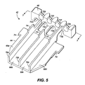
- FIG. 5 depicts a wire/conductor carrier or mandrel 42 having a substantially planar body 44 terminated by a conductor distribution end 46.
- Mandrel 42 as illustrated in FIG. 5, is designed to terminate an eight-wire (i . e ., four-pair) cable such as exemplary cable 48 shown in FIG. 6 and is typically constructed from a non-conducting, low dielectric material such as plastic.
- eight-wire i . e ., four-pair
- Cable 48 which is representative of communication cables commonly used in the art and illustrated in FIG. 6.
- Cable 48 comprises eight, insulated conductors or wires held in a protective sheath 39 typically made from poly-vinyl chloride (PVC) or other suitable material.
- the eight conductors are generally arranged in four, two-wire pairs in which the wires comprising each pair twist around one another throughout the length of cable 48.
- the wire pairs themselves generally twine or twist around one another as well. In the example shown in FIG.
- the first wire pair comprises dark blue wire 52 and light blue wire 54; the second wire pair comprises white wire 56 and orange wire 58; the third wire pair comprises dark green wire 60 and light green wire 62; and the fourth wire pair comprises dark brown wire 64 and light brown wire 66.
- the colors assigned to the wire insulation are exemplary of a common identification method used in eight-wire communication cables. It is well known in the art that twisting the individual wires comprising the wire pairs and twining the wire pairs around each other serves to substantially reduce crosstalk between the wires in the cable.
- mandrel body 44 is shown to be subdivided into four channels 68a,b,c,d via dividing walls 70a,b,c.
- Channels 68a,b,c,d each receive one of the wire pairs from cable 48.
- the plug assembly person will strip away a portion of sheath 39 to expose the wire pairs contained inside.
- the wire pairs in cable 48 are positioned in a generally circular arrangement. Therefore, the assembly person must reconfigure not only the wire pairs themselves, but the individual wires into a substantially planar arrangement having a predetermined ordering according to the signal or electrical assignments given to terminals 22.
- the unique design of mandrel 42 facilitates this orientation process via the combination of channels 68 and positioning slots 72.
- wire pairs are each assigned a channel 68 according to the required mapping of the wires to terminals 22.
- pair IV (wires 64 and 66) is assigned to channel 68a;
- pair I (wires 52 and 54) is assigned to channel 68b;
- pair III (wires 60 and 62) is assigned to channel 68c;
- pair II (wires 56 and 58) is assigned to channel 68d.
- mandrel 42 is slid up into sheath 39 until the edge of sheath 39 abuts up against stops 74.
- mandrel 42 allows the pair orientation (i . e ., twist) in the wire pairs to be maintained along the length of mandrel body 44 thus minimizing the onset of crosstalk.
- Dividing walls 70a,b,c, combat crosstalk that can develop between the wire pairs along with directing the wires towards their appropriate slots in conductor distribution end 46.
- other electrical parameters can also be optimized with a mandrel such as this. Equally important, however, is that these advantages are maintained within the engagement region of anchor bar 32 with sheath 39 (see FIG. 4) when mandrel 42 is inserted into plug 20 to complete the assembly. That is, mandrel 42 ensures that anchor bar 32 does not deform or distort the arrangement of the conductors while still cooperating with anchor bar 32 to provide the necessary strain relief.
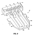
- FIG. 7 depicts a common mapping between the individual wires and slots 72a,b,c,d,e,f,g,h.
- the assigned slots 72 correspond with the assigned channels 68 for the wire pair; however, for pair III held in channel 68c, dark green wire 60 and light green wire 62 are split up to route to slots 72c and 72f respectively. This procedure typically involves running dark green wire 60 either over or under pair I comprising dark blue wire 52 and light blue wire 54.
- Alignment region 28 includes a set of passages or channels 29 having a compatible configuration to slots 72 for receiving the individual wires (i.e., channels 29 and slots 72 having the same letter designation are aligned with one another; see, e.g., FIGS. 2, 5 and 7).
- This allows the assembly person to insert the wires into channels 29 until the wire ends reach the terminals 22 located towards the nose end of communication plug 20.
- terminals 22 are then pressed down into the wires thereby penetrating the outer insulation with their prongs 30 to form an electrical connection.
- one of the significant benefits of the present invention is the ability to maintain the pair orientation to prevent crosstalk even as the wires approach terminals 22 for connection.
- legacy systems i . e ., current jacks
- Legacy jacks are engineered to compensate for crosstalk in the communication plug; thus, a well designed plug should generate crosstalk that is complementary to that used in the jack so the combination of the two crosstalk signals cancel each other out.
- Sled 76 is designed with apertures and slots 78 ( i . e ., channels) that match slots 72 in conductor distribution end 46.
- sled 76 acts as a spacer between conductor distribution end 46 of mandrel 42 and alignment region 28 of communication plug 20.
- sled 76 can be milled or molded to an appropriate length to generate the desired amount of crosstalk to adapt communication plug 20 to the crosstalk characteristics of a legacy jack.
- Sled 76 optimizes crosstalk between the wires by adjusting the length in which the wires are untwisted and run parallel to one another.
- mandrel 42 and sled 76 can be modified or combined with other components to provide alternative crosstalk adaptation mechanisms such as changing the positioning of the conductors with respect to one another to alter their electrical characteristics.
- alternative design or manufacturing schemes may be employed such as combining mandrel 42 and sled 76 into a unitary component or integrating either or both mandrel 42 and sled 76 with plug 20.
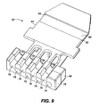
- depression region 80 An additional feature of mandrel 42 is depression region 80 as shown in FIG. 9. Recall from the discussion surrounding anchor bar 32, which was illustrated in FIG. 4, that anchor bar surface 34 engages cable jacket or sheath 39 in chamber 26. Also recall from the foregoing discussion that mandrel 42 is slid underneath sheath 39 during the installation process. Thus, depression region 80 provides a means for receiving the portion of sheath 39 that is depressed by anchor bar surface 34. Flanges 82 defining the width of depression region provide an impediment to movement of mandrel 42 once secured by anchor bar 32.
- mandrel 42 is oriented with depression region 80 positioned proximal to anchor bar 32 in the preferred embodiment, the invention may nevertheless still be practiced with mandrel 42 turned upside down from this configuration such that anchor bar 32 engages dividing walls 70a,b,c through sheath 39 to secure the cable and mandrel assembly.
- new communication plugs must be capable of adapting to legacy wall jacks that require a certain amount of crosstalk to be generated in the plug if they are to be successful in today's marketplace. Nevertheless, it is envisioned that future applications may require communication plugs that minimize crosstalk to the greatest extent possible.
- Mandrel 142 incorporates the same body 44 that was used in mandrel 42, but includes an extended conductor distribution end 146.
- Extended conductor distribution end 146 replaces the function of alignment region 28 in communication plug 20 (see FIG. 1).
- chamber 26 of plug 120 extends under terminals 22 into the space formerly occupied by alignment region 28.
- Extended conductor distribution end 146 is received into chamber 26 and is positioned under terminals 22.
- extended conductor distribution end 146 includes slots 84 that provide a passage way for dual prongs 30 of contacts 22 to reach the wires contained therein. Terminals 22 are crimped onto the wires held in extended conductor distribution end 146 to form the electrical connections.
- Mandrel 142 allows the twist in the individual wire pairs to be maintained up until the wires are routed to their respective slots in extended conductor distribution end 146. Accordingly, crosstalk between the wire pairs is kept to a minimum because the length in which the wire pairs are untwisted and running parallel to one another is kept at a minimum.
- Mandrel 142 substantially reduces assembly time over prior art conununication plug designs. Once a portion of sheath 39 is removed from the end of the cable, an assembly person can insert mandrel 142 underneath cable sheath 39, untwist each wire pair and snap the individual wires into their respective slots 72 outside of communication plug 120. At this point, completion of the plug assembly is simple as the wires are trimmed and mandrel 142 is inserted into chamber 26 until extended distribution end 146 reaches terminals 22 at the nose of the plug. In this position, terminals 22 are crimped onto the wires and anchor bar 32 (see FIG. 4) is locked into its operative position to secure the cable in place.
- the unique plug can be configured to optimize crosstalk generated therein through precise milling of an inexpensive sled component in conjunction with a mandrel for routing the individual wires to their proper locations.
- a uniquely designed mandrel can be used that allows the twist in the individual wire pairs to be moved as close as possible to the electrical contacts.
- the crosstalk minimization mandrel minimizes assembly time by allowing all wire manipulation to be done external to the plug housing.
- the carrier or mandrel disclosed herein can be applied as a cable termination for any jacketed cable.
- the mandrel is inserted under the cable jacket and receives the conductors in channels formed therein to organize the positioning and routing of the conductors as they exit the end of the cable jacket.
- the mandrel maintains this organization while an anchor bar or similar strain relief mechanism is tightened over the jacket, mandrel and conductors.
- the mandrel can extend beyond the end of the jacket to provide alignment and/or rearrangement of conductor positions up to a termination device such as a plug carrying terminal contacts.
Landscapes
- Details Of Connecting Devices For Male And Female Coupling (AREA)
- Multi-Conductor Connections (AREA)
- Coupling Device And Connection With Printed Circuit (AREA)
Claims (8)
- Verbindungsstecker (20) zum Abschließen eines Kabels (48, das eine Mehrzahl verdrillter Leiterpaare (52, 54), (56, 58), (60, 62), (64, 66) enthält und das von einem äußeren Mantel (30) umschlossen ist; wobei der Stecker Folgendes aufweist:ein im Wesentlichen hohles Gehäuseelement (21) mit einem offenen Ende und einem geschlossenen Ende sowie mit einer oberen Wand, einer unteren Wand und Seitenwänden;einen Leiterträger (42) im Inneren des Gehäuses, wobei der Leiterträger einen Verteilerbereich (46) aufweist,dadurch gekennzeichnet, dass der Leiterträger einen im Wesentlichen planaren Körper (44) aufweist, der sich derart in das Kabel einsetzen lässt, dass er zwischen die verdrillten Paare sowie den Kabel-Außenmantel passt;wobei an dem planaren Körper eine Mehrzahl von in Längsrichtung verlaufenden, offenen Kanälen (68a-d) ausgebildet ist und jeder der Kanäle zum Aufnehmen von einem der verdrillten Leiterpaare konfiguriert ist;und dass der Verteilerbereich sich von dem planaren Körper in Längsrichtung weg erstreckt und von diesem beabstandet ist sowie eine obere und eine untere Oberfläche aufweist, wobei der Verteilerbereich in seiner oberen und unteren Oberfläche mit einer Mehrzahl von Schlitzen (72a-h) ausgebildet ist und jeder der Schlitze dazu konfiguriert ist, einen Einzelleiter eines verdrillten Paares derart auszurichten, dass die Leiter ein vorbestimmtes Muster bilden.
- Verbindungsstecker nach Anspruch 1,
wobei die Kanäle durch eine Mehrzahl voneinander beabstandeter, in Längsrichtung verlaufender Trennwände gebildet sind, die sich von dem planaren Körper nach oben erstrecken. - Verbindungsstecker nach Anspruch 1,
weiterhin mit einem an dem geschlossenen Ende des Gehäuses vorgesehenen Ausrichtungsbereich, der eine Mehrzahl von Kanälen zum Aufnehmen der in dem vorbestimmten Muster angeordneten Leiter aufweist; und
mit einer Mehrzahl leitfähiger Anschlüsse, die in dem Gehäuse gehalten sind und nahe dem Ausrichtungsbereich positioniert ist, wobei jeder der Anschlüsse eine Verbindungseinrichtung an einem Leiter-Schnittstellenende aufweist, um mit einem der in den Kanälen des Ausrichtungsbereichs gehaltenenen Leitern elektrischen Kontakt herzustellen. - Verbindungsstecker nach Anspruch 3,
weiterhin mit einer Nebensprech-Festlegeeinrichtung zum Einrichten eines Nebensprech-Pegels, die zwischen dem Ausrichtungsbereich und dem Verteilerbereich angeordnet ist. - Verbindungsstecker nach Anspruch 4,
wobei die Nebensprech-Festlegeeinrichtung einen Schlitten aufweist, der eine Mehrzahl von dem vorbestimmten Muster entsprechenden Kanälen zum Aufnehmen der Leiter besitzt. - Verbindungsstecker nach Anspruch 3,
wobei in der oberen Wand des Gehäuseelements eine Öffnung ausgebildet ist; und
wobei in der Öffnung eine Verankerungsstange angeordnet ist und mit dem hohlen Inneren des Gehäuseelements in Verbindung steht, um das Kabel in dem Gehäuseelement zu verankern und Spannungsbelastungen auf die Verbindungen zwischen den Leitern und den leitfähigen Anschlüssen zu reduzieren. - Verbindungsstecker nach Anspruch 6,
wobei der im Wesentlichen planare Körper eine Bodenfläche mit einer darin vorhandenen Vertiefung aufwelst, wobei die Vertiefung nahe der Verankerungsstange ausgerichtet ist, so dass in das hohle Gehäuseelement hineinreichende Erweiterungen der Verankerungsstange einen Bereich des äußeren Mantels des Kabels mlt der Vertiefung in Eingriff drücken. - Verbindungsstecker nach Anspruch 7,
wobei sich die Vertiefung in Querrichtung über die Bodenfläche des im Wesentlichen planaren Körpers erstreckt.
Applications Claiming Priority (2)
| Application Number | Priority Date | Filing Date | Title |
|---|---|---|---|
| US52528 | 1987-05-20 | ||
| US09/052,528 US6280232B1 (en) | 1998-03-31 | 1998-03-31 | Communication cable termination |
Publications (2)
| Publication Number | Publication Date |
|---|---|
| EP0948099A1 EP0948099A1 (de) | 1999-10-06 |
| EP0948099B1 true EP0948099B1 (de) | 2006-06-07 |
Family
ID=21978206
Family Applications (1)
| Application Number | Title | Priority Date | Filing Date |
|---|---|---|---|
| EP99302190A Expired - Lifetime EP0948099B1 (de) | 1998-03-31 | 1999-03-22 | Verbinder für Kommunikation Kabel |
Country Status (5)
| Country | Link |
|---|---|
| US (1) | US6280232B1 (de) |
| EP (1) | EP0948099B1 (de) |
| AU (1) | AU748769B2 (de) |
| CA (1) | CA2265027C (de) |
| DE (1) | DE69931689T2 (de) |
Families Citing this family (39)
| Publication number | Priority date | Publication date | Assignee | Title |
|---|---|---|---|---|
| US6558204B1 (en) * | 1999-02-19 | 2003-05-06 | Richard Weatherley | Plug assembly for data transmission and method of wiring same |
| US6561838B1 (en) * | 1999-12-13 | 2003-05-13 | Adc Telecommunications, Inc. | Connector plug and insert for twisted pair cables |
| US6524128B2 (en) * | 2000-06-02 | 2003-02-25 | Stewart Connector Systems, Inc. | Modular plug wire aligner |
| US6506077B2 (en) * | 2000-07-21 | 2003-01-14 | The Siemon Company | Shielded telecommunications connector |
| FR2814598B1 (fr) * | 2000-09-27 | 2002-11-29 | Fci France | Connecteur muni de contacts montes dans un isolant adapte |
| US6579116B2 (en) * | 2001-03-12 | 2003-06-17 | Sentinel Holding, Inc. | High speed modular connector |
| US6409544B1 (en) * | 2001-05-23 | 2002-06-25 | Lorom Industrial Co., Ltd. | Network data transmission cable connector |
| US6439920B1 (en) * | 2001-09-18 | 2002-08-27 | Surtec Industries Inc. | Electronic connector plug for high speed transmission |
| US6811445B2 (en) | 2002-04-22 | 2004-11-02 | Panduit Corp. | Modular cable termination plug |
| USD478321S1 (en) | 2002-10-25 | 2003-08-12 | John Peng | Inner sleeve of a net plug |
| TW568403U (en) * | 2003-05-09 | 2003-12-21 | Surtec Ind Inc | Plug of high-speed electronic connector |
| US7017267B2 (en) * | 2003-10-15 | 2006-03-28 | James Allen Carroll | Method and apparatus for zone cabling |
| US10680385B2 (en) | 2004-02-20 | 2020-06-09 | Commscope Technologies Llc | Methods and systems for compensating for alien crosstalk between connectors |
| US7187766B2 (en) | 2004-02-20 | 2007-03-06 | Adc Incorporated | Methods and systems for compensating for alien crosstalk between connectors |
| US20050221678A1 (en) | 2004-02-20 | 2005-10-06 | Hammond Bernard Jr | Methods and systems for compensating for alien crosstalk between connectors |
| US20060160407A1 (en) * | 2004-06-24 | 2006-07-20 | Carroll James A | Network connection system |
| WO2007084095A2 (en) * | 2004-06-24 | 2007-07-26 | Carroll James A | Network connection system |
| US7335066B2 (en) * | 2005-12-16 | 2008-02-26 | James A. Carroll | Network connector and connection system |
| US7661980B2 (en) * | 2007-10-18 | 2010-02-16 | The Boeing Company | Cable connector assembly with wire termination guide |
| US8141965B2 (en) * | 2008-06-11 | 2012-03-27 | Adc Telecommunications, Inc. | L-shaped door with three-surface seal for endplates |
| US7812254B2 (en) * | 2008-06-11 | 2010-10-12 | Adc Telecommunications, Inc. | Solar shields |
| US8254850B2 (en) * | 2008-06-11 | 2012-08-28 | Adc Telecommunications, Inc. | Communication module component assemblies |
| US8019396B2 (en) * | 2008-06-11 | 2011-09-13 | Adc Telecommunications, Inc. | Pull-out shelf for use in a confined space formed in a structure |
| US8145442B2 (en) * | 2009-01-30 | 2012-03-27 | Synopsys, Inc. | Fast and accurate estimation of gate output loading |
| US8993887B2 (en) * | 2009-11-09 | 2015-03-31 | L-Com, Inc. | Right angle twisted pair connector |
| CN107508724B (zh) | 2010-04-29 | 2022-03-08 | 克里斯多佛·布赖恩德·谢勒 | 联网电缆追踪器系统 |
| US8979553B2 (en) * | 2012-10-25 | 2015-03-17 | Molex Incorporated | Connector guide for orienting wires for termination |
| CA2898709C (en) | 2013-01-18 | 2021-02-16 | Christopher B. Scherer | Field-terminable traceable cables, components, kits, and methods |
| TWI628672B (zh) | 2013-08-21 | 2018-07-01 | 克里斯多福B 雪羅 | 用於傳輸資料之網路化排線及組裝用於網路化排線之連接器罩之方法 |
| US9640924B2 (en) | 2014-05-22 | 2017-05-02 | Panduit Corp. | Communication plug |
| US10411398B2 (en) | 2015-08-12 | 2019-09-10 | Commscope Technologies Llc | Electrical plug connector |
| US10128647B2 (en) * | 2015-12-21 | 2018-11-13 | Te Connectivity Corporation | Cable management clasp |
| KR102390264B1 (ko) * | 2016-05-04 | 2022-04-22 | 센티넬 커넥터 시스템즈, 아이엔씨. | 산업용 대형 도체 플러그 |
| US11158980B2 (en) | 2018-11-30 | 2021-10-26 | Commscope Technologies Llc | Modular telecommunications plug and method |
| WO2020113023A1 (en) | 2018-11-30 | 2020-06-04 | Commscope Technologies Llc | Modular telecommunications plug and method |
| US11689247B2 (en) | 2019-01-16 | 2023-06-27 | Mertek Industries, Llc | Patch cord including wireless components |
| EP3997762B1 (de) | 2019-07-11 | 2025-12-03 | CommScope Technologies LLC | Modularer telekommunikationsstecker und verfahren |
| US12300943B2 (en) | 2019-09-30 | 2025-05-13 | Mertek Industries, Llc | Patch panel traceable networking system |
| US20220133965A1 (en) * | 2020-11-02 | 2022-05-05 | Medtronic, Inc. | Interconnect design for joining dissimilar materials |
Family Cites Families (10)
| Publication number | Priority date | Publication date | Assignee | Title |
|---|---|---|---|---|
| US4607905A (en) * | 1985-04-18 | 1986-08-26 | Brand-Rex Company | Modular plug |
| US5249987A (en) * | 1992-03-31 | 1993-10-05 | Virginia Patent Development Corporation | Cap for modular jack |
| US5186649A (en) | 1992-04-30 | 1993-02-16 | At&T Bell Laboratories | Modular plug having enhanced cordage strain relief provisions |
| US5194014A (en) * | 1992-05-20 | 1993-03-16 | Stewart Connector Systems, Inc. | Cable connector and contact terminal therefor |
| US5571035A (en) * | 1994-10-31 | 1996-11-05 | The Whitaker Corporation | Divergent load bar |
| US5505638A (en) | 1994-11-18 | 1996-04-09 | Su; Gorden | Telephone plug module |
| DE69522300T2 (de) | 1994-12-05 | 2002-05-02 | The Whitaker Corp., Wilmington | Modulstecker für Hochgeschwindigkeits-Datentransfer |
| GB9603751D0 (en) * | 1996-02-22 | 1996-04-24 | Amp Espa Ola S A | Twisted pair cable and connector assembly |
| US5899770A (en) * | 1996-11-05 | 1999-05-04 | Hirose Electric Co., Ltd. | Modular plug and modular jack |
| US5772465A (en) | 1996-11-15 | 1998-06-30 | Hwang; Wayne | Connector structure accommodating de-twisted wire pairs |
-
1998
- 1998-03-31 US US09/052,528 patent/US6280232B1/en not_active Expired - Lifetime
-
1999
- 1999-03-08 CA CA002265027A patent/CA2265027C/en not_active Expired - Fee Related
- 1999-03-22 EP EP99302190A patent/EP0948099B1/de not_active Expired - Lifetime
- 1999-03-22 DE DE69931689T patent/DE69931689T2/de not_active Expired - Lifetime
- 1999-03-26 AU AU22439/99A patent/AU748769B2/en not_active Ceased
Also Published As
| Publication number | Publication date |
|---|---|
| DE69931689T2 (de) | 2007-06-14 |
| EP0948099A1 (de) | 1999-10-06 |
| AU2243999A (en) | 1999-10-14 |
| US6280232B1 (en) | 2001-08-28 |
| DE69931689D1 (de) | 2006-07-20 |
| CA2265027A1 (en) | 1999-09-30 |
| CA2265027C (en) | 2003-05-20 |
| AU748769B2 (en) | 2002-06-13 |
Similar Documents
| Publication | Publication Date | Title |
|---|---|---|
| CA2265027C (en) | Communication cable termination | |
| CA2288917C (en) | Communication cable terminating plug | |
| CA2244653C (en) | Strain relief apparatus for use in a communication plug | |
| US7425159B2 (en) | Metallized sled for communication plug | |
| AU741458B2 (en) | Low crosstalk assembly structure for use in a communication plug | |
| AU741508B2 (en) | Alignment apparatus for use in the jack interface housing of a communication plug | |
| US7905015B2 (en) | Method for terminating a telecommunications cable | |
| EP0899828B1 (de) | Nachrichtenstecker | |
| CA2244652C (en) | Blade carrier for use in a communication plug | |
| MXPA02000940A (es) | Conector de telecomunicaciones protegido. | |
| WO2001043231A2 (en) | Connector plug and insert for twisted pair cables | |
| CA2712846A1 (en) | Wire lead guide and method for terminating a communications cable |
Legal Events
| Date | Code | Title | Description |
|---|---|---|---|
| PUAI | Public reference made under article 153(3) epc to a published international application that has entered the european phase |
Free format text: ORIGINAL CODE: 0009012 |
|
| AK | Designated contracting states |
Kind code of ref document: A1 Designated state(s): DE |
|
| AX | Request for extension of the european patent |
Free format text: AL;LT;LV;MK;RO;SI |
|
| AKX | Designation fees paid |
Free format text: DE |
|
| 17P | Request for examination filed |
Effective date: 20000518 |
|
| 17Q | First examination report despatched |
Effective date: 20050502 |
|
| GRAP | Despatch of communication of intention to grant a patent |
Free format text: ORIGINAL CODE: EPIDOSNIGR1 |
|
| RIC1 | Information provided on ipc code assigned before grant |
Ipc: 7H 01R 24/00 A |
|
| GRAS | Grant fee paid |
Free format text: ORIGINAL CODE: EPIDOSNIGR3 |
|
| GRAA | (expected) grant |
Free format text: ORIGINAL CODE: 0009210 |
|
| AK | Designated contracting states |
Kind code of ref document: B1 Designated state(s): DE |
|
| REF | Corresponds to: |
Ref document number: 69931689 Country of ref document: DE Date of ref document: 20060720 Kind code of ref document: P |
|
| PLBE | No opposition filed within time limit |
Free format text: ORIGINAL CODE: 0009261 |
|
| STAA | Information on the status of an ep patent application or granted ep patent |
Free format text: STATUS: NO OPPOSITION FILED WITHIN TIME LIMIT |
|
| 26N | No opposition filed |
Effective date: 20070308 |
|
| PGFP | Annual fee paid to national office [announced via postgrant information from national office to epo] |
Ref country code: DE Payment date: 20100329 Year of fee payment: 12 |
|
| PG25 | Lapsed in a contracting state [announced via postgrant information from national office to epo] |
Ref country code: DE Free format text: LAPSE BECAUSE OF NON-PAYMENT OF DUE FEES Effective date: 20111001 |
|
| REG | Reference to a national code |
Ref country code: DE Ref legal event code: R119 Ref document number: 69931689 Country of ref document: DE Effective date: 20111001 |