EP0948029B1 - Lampe à décharge haute pression - Google Patents
Lampe à décharge haute pression Download PDFInfo
- Publication number
- EP0948029B1 EP0948029B1 EP99302297A EP99302297A EP0948029B1 EP 0948029 B1 EP0948029 B1 EP 0948029B1 EP 99302297 A EP99302297 A EP 99302297A EP 99302297 A EP99302297 A EP 99302297A EP 0948029 B1 EP0948029 B1 EP 0948029B1
- Authority
- EP
- European Patent Office
- Prior art keywords
- vessel
- stopper
- electrode unit
- frit seal
- discharge lamp
- Prior art date
- Legal status (The legal status is an assumption and is not a legal conclusion. Google has not performed a legal analysis and makes no representation as to the accuracy of the status listed.)
- Expired - Lifetime
Links
Images


Classifications
-
- H—ELECTRICITY
- H01—ELECTRIC ELEMENTS
- H01J—ELECTRIC DISCHARGE TUBES OR DISCHARGE LAMPS
- H01J61/00—Gas-discharge or vapour-discharge lamps
- H01J61/02—Details
- H01J61/36—Seals between parts of vessels; Seals for leading-in conductors; Leading-in conductors
- H01J61/366—Seals for leading-in conductors
Definitions
- the present invention relates to a high pressure discharge lamp such as sodium-vapor lamp, metal halide lamp or the like.
- FIG. 1 Conventional high pressure discharge lamp is shown in Fig. 1, and includes a vessel 1 made of a non-conductive material (e.g. alumina) which forms an inner space filled with an ionizable light-emitting material and a starting gas.
- a tubular capillary member 2 is arranged at one opening portion of the vessel, and has an outer diameter which is substantially the same as an inner diameter of the first opening portion.
- An electrode unit 3 is inserted into the capillary member 2 and has an outer diameter which is smaller than an inner diameter of the capillary member 2.
- a gap formed between the inner surface of the capillary member 2 and the outer surface of the electrode unit 3 is filled with a frit seal 4.
- a frit seal 4 there may occur fluctuation of the axial position of the frit seal 4 in the capillary member 2, as represented by "d" in Fig. 1, so that the axially inner end of the frit seal is not uniformly positioned around the electrode unit.
- Such fluctuation makes it difficult to maintain a substantially constant volume of the ionizable light-emitting material and the starting gas flowing into the capillary 2, and realize a uniform property of the discharge lamps.
- a corrosive material is used as the ionizable light-emitting material, the tendency of the corrosiveness of the electrode unit 3 is notable if the electrode unit 3 is excessively exposed to the discharge space of the vessel 1.
- EP-A-0 573 880 discloses a high pressure discharge lamp wherein a tight seal between a solid niobium or tantalum connecting pin or rod passing through an opening in an end plug of the vessel is formed with externally projecting continuous rings, or an externally projecting thread.
- the rings or thread are press-fitted into the end portion of the bore in the plug, which deforms the edge of the rim, ridge or thread, or shears off the edge portion, ensuring a tight preliminary fit in the bore. Sealing glass is melted to fill a capillary space between the pin or rod and the plug.
- a frit seal is filled in a gap which is formed by the tubular member, the stopper and the electrode unit, with the stopper defining an inner end position of the frit seal in the tubular member.
- the axially inner end of the frit seal can be uniformly positioned around the electrode unit by the stopper without the control of the temperature of the frit seal.
- the porous material which can be suitably used in the present invention has a number of pores with an average pore diameter of approximately 1 to 10 ⁇ m and a porosity of not less than approximately 30%.
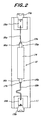
- Fig. 2 shows the structure of the high pressure discharge lamp as a whole, which is in accordance with the present invention.
- the high pressure lamp includes an outer tube 11 made of quartz glass or hard glass, and a ceramic discharge tube 12 is placed in the outer tube 11 coaxially thereto.
- the ceramic discharge tube 12 comprises a tubular vessel 14 made of alumina, tubular member in the form of capillary members 16a, 16b made of alumina and provided at both ends 15a, 15b of the tubular vessel 14, respectively, and electrode units 17a, 17b inserted into the capillary members 16a, 16b, respectively.
- the ceramic discharge tube 2a is held by the outer tube 11 via two lead wires 18a, 18b.
- the lead wires 18a, 18b are connected to the respective caps 13a, 13b via respective foils 19a, 19b.
- Fig. 3 is a sectional view showing a first exampleof the end portion of the vessel in the embodiment shown in Fig. 2.
- a vessel 14 has a tubular body 20 and a disc 21.
- the electrode unit 17a comprises a cylindrical member 22 made of niobium, a cylindrical member 23 made of cermet of molybdenum and conductive material which is jointed at the bottom of the cylindrical member 22 without being exposed to outside of the vessel 14, and an electrode 24 which is jointed at the bottom of the cylindrical member 23 exposed to the inner space of the vessel 14.
- the electrode 24 is provided with a coil 25 in a conventional manner.
- a stopper 27 inserted by the electrode unit defines an inner end position of a frit seal 26 in the tubular member 16a.
- the stopper 27 comprises a porous member having a number of pores with an average pore diameter of approximately 1 to 10 ⁇ m and a porosity of not less than approximately 30%.
- a gap formed between an inner surface of the capillary member 16a, an upper end of the stopper 27 and an outer surface of the electrode unit 22 is filled with the frit seal 26.
- the axially inner end of the frit seal 26 is uniformly positioned around the electrode unit 17a without requiring a control of the temperature of the frit seal 26. Further, by composing the stopper 27 by a porous member, an extra frit seal is absorbed in the porous member even if an excess frit seal 26 is filled with the gap. Therefore, the axially inner end of the frit seal 26 is uniformly positioned around the electrode unit 17a without the control of the volume of the frit seal 26. Due to uniform axial position of the frit seal in the capillary member 16a, the property of the discharge lamp is prevented from undesirable fluctuation. Moreover, even when a material having a corrosiveness is used as an ionizable light-emitting material, the corrosiveness of the electrode unit 3 does not proceed.
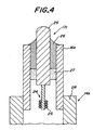
- Fig. 4 is a sectional view showing a second example of the end portion of the vessel shown in Fig. 2.
- the vessel 14a only has a cylindrical main body 28.
- An electrode unit 17c has a cylindrical member 29 made of molybdenum, and an electrode 24 jointed at the end of the cylindrical member 29 exposed to the inner space of the vessel 14a.
- the stopper 27 positively defines an inner end position of the frit seal 26 in the capillary member 16a.
- Fig. 5 is a sectional view showing a third example of the end portion of the vessel shown in Fig. 2.
- a vessel 14b comprises a cylindrical main body 30 having an annular collar which forms a inner space of the vessel and defines opening portions at both ends thereof.
- An electrode unit 17d has a tubular holding member 31 for electrode unit, and the electrode 24 is tightly jointed by welding at the end of the unit-holding member 31 as being exposed to the inner space of the vessel 14b.
- the end of the holding member 31 is sealed by laser welding or TIG welding.
- Fig. 6 is a sectional view showing a forth example of the end portion of the vessel shown in Fig. 2.
- an electrode unit 17e has a electrode unit-holding member 32 of which an electrode 24 is jointed at the bottom by welding.
- the electrode unit-holding member 32 is inserted into a tubular member 32 so that the electrode 24 is exposed to the inner space of the vessel 14a.
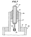
- Fig. 7 is a sectional view showing a fifth example of the end portion of the vessel shown in Fig. 2.
- an electrode member 17f has a substantially cylindrical member 34 which has a cylindrical member made of non-conductive material (e.g. alumina) coated with a mixture of a metal (e.g. molybdenum) and a non-conductive material (e.g. alumina), and the electrode 24 jointed at the bottom of the substantially cylindrical member 34 exposed to the inner space of the vessel 14a.
- non-conductive material e.g. alumina
- a metal e.g. molybdenum
- a non-conductive material e.g. alumina
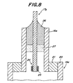
- Fig. 8 is a sectional view showing a fifth example of the end portion of the vessel shown in Fig. 2.
- an electrode 17g may be constituted of a single electrode 24.
- Fig. 9 is a flowchart illustrating the process steps for manufacturing the high pressure discharge lamp according to the present invention.
- alumina or cermet powder granulated by a spray drier or the like is press-molded under the pressure of 2000 to 3000 kgf/cm 2 to obtain a molded body for the capillary member.
- alumina or cermet powder granulated by a spray drier or the like is press-molded under the pressure of 0.6 to 0.8 times of the pressure when the molded body for the capillary member is manufactured to obtain a molded body for the stopper constituted by a porous member.
- these molded bodies formed as such are dewaxed by heating at the temperature of 600 to 800°C, and calcined by heating at the temperature of 1200 to 1400°C in a hydrogen-reduced atmosphere, respectively.
- a strength is more or less given to the molded bodies to facilitate handling of the capillary member and the stopper.
- the composite electrode is processed and assembled in parallel with the molding, dewaxing and calcining of the capillary member and the stopper. Moreover, the vessel of the ceramic discharge tube is molded, and the calcined body for the ceramic discharge tube is obtained by dewaxing and calcining the molded body.
- the calcined body for the capillary member is inserted and set into the end face of the calcined body for the ceramic discharge tube, and the calcined body for the stopper is then inserted and set into the calcined body for the capillary body at a position to be filled with the frit seal by a conductive rod, and the assembly is subjected to finish-firing at the temperature of 1600 to 1900°C in a reducing atmosphere having a dew point of -15 to 15°C.
- the electrode unit is subsequently inserted into the capillary member, so a gap is formed by the inner end of the capillary, the upper end of the stopper and the inner surface of the electrode unit, and filled with the frit seal to obtain the high pressure discharge lamp of the present invention.
- a non-conductive material other than alumina e.g. cermet
- the vessel and the capillary member are formed by a same material, however the material forming the vessel may be different from that forming the capillary (For example, the vessel is made of alumina and the capillary is made of cermet.).
- the vessel may take any other form than the tubular form or the barrel form.
- the electrode does not have to have the coil.
- the cylindrical member 23 is composed of cermet of molybdenum and conductive material, however it may be composed of cermet of tungsten and conductive material.
- the electrode unit is inserted into the capillary member, however, the vessel, the capillary member and the electrode unit-holding member may assembled after the stopper is inserted into the electrode unit to be co-firing them into an integrated body.
Claims (1)
- Lampe à décharge haute pression comprenant :caractérisée en ce que ladite butée d'arrêt (27) comprend un élément poreux non conducteur.un récipient (14, 14a, 14b) réalisé en un matériau non conducteur qui forme un espace interne rempli d'un matériau ionisable émetteur de lumière et d'un gaz d'amorce, ledit récipient ayant une ouverture à l'une de ses extrémités;un élément tubulaire (16a) disposé à ladite ouverture du récipient et ayant un diamètre extérieur qui est sensiblement le même que le diamètre intérieur de ladite ouverture;une unité d'électrodes (17a-17g) insérée dans ledit élément tubulaire et ayant un diamètre extérieur qui est plus petit que le diamètre intérieur dudit élément tubulaire;une butée d'arrêt (27) agencée entre ledit élément tubulaire et ladite unité d'électrodes et ayant un diamètre extérieur qui est sensiblement le même que ledit diamètre intérieur dudit élément tubulaire, ladite butée d'arrêt ayant un trou dans lequel ladite électrode est insérée; etun joint fritté (26) introduit dans un espace qui est formé par ledit élément tubulaire, ladite butée d'arrêt et ladite unité d'électrodes, ladite butée d'arrêt définissant une position d'extrémité interne dudit joint fritté dans ledit élément tubulaire,
Applications Claiming Priority (2)
| Application Number | Priority Date | Filing Date | Title |
|---|---|---|---|
| JP10083824A JPH11283569A (ja) | 1998-03-30 | 1998-03-30 | 高圧放電灯 |
| JP8382498 | 1998-03-30 |
Publications (3)
| Publication Number | Publication Date |
|---|---|
| EP0948029A2 EP0948029A2 (fr) | 1999-10-06 |
| EP0948029A3 EP0948029A3 (fr) | 1999-10-13 |
| EP0948029B1 true EP0948029B1 (fr) | 2003-12-10 |
Family
ID=13813449
Family Applications (1)
| Application Number | Title | Priority Date | Filing Date |
|---|---|---|---|
| EP99302297A Expired - Lifetime EP0948029B1 (fr) | 1998-03-30 | 1999-03-24 | Lampe à décharge haute pression |
Country Status (4)
| Country | Link |
|---|---|
| US (1) | US6392345B1 (fr) |
| EP (1) | EP0948029B1 (fr) |
| JP (1) | JPH11283569A (fr) |
| DE (1) | DE69913410T2 (fr) |
Families Citing this family (10)
| Publication number | Priority date | Publication date | Assignee | Title |
|---|---|---|---|---|
| US6635993B1 (en) | 1998-08-26 | 2003-10-21 | Ngk Insulators, Ltd. | Joined bodies, high-pressure discharge lamps and a method for manufacturing the same |
| JP4613408B2 (ja) * | 1999-10-15 | 2011-01-19 | 日本碍子株式会社 | 高圧放電灯用発光管の製造方法 |
| US20020033670A1 (en) * | 2000-07-03 | 2002-03-21 | Ngk Insulators, Ltd. | Joined body and a high pressure discharge lamp |
| US6774185B2 (en) | 2001-04-04 | 2004-08-10 | Bridgestone Corporation | Metal hydroxide filled rubber compositions and tire components |
| US6856079B1 (en) | 2003-09-30 | 2005-02-15 | Matsushita Electric Industrial Co., Ltd. | Ceramic discharge lamp arc tube seal |
| CN1969366B (zh) * | 2004-06-14 | 2011-06-08 | 皇家飞利浦电子股份有限公司 | 陶瓷金属卤化物放电灯 |
| US20060001346A1 (en) * | 2004-06-30 | 2006-01-05 | Vartuli James S | System and method for design of projector lamp |
| US7164232B2 (en) * | 2004-07-02 | 2007-01-16 | Matsushita Electric Industrial Co., Ltd. | Seal for ceramic discharge lamp arc tube |
| US7358674B2 (en) * | 2004-07-27 | 2008-04-15 | General Electric Company | Structure having electrodes with metal core and coating |
| US7511429B2 (en) | 2006-02-15 | 2009-03-31 | Panasonic Corporation | High intensity discharge lamp having an improved electrode arrangement |
Family Cites Families (4)
| Publication number | Priority date | Publication date | Assignee | Title |
|---|---|---|---|---|
| DE9207816U1 (fr) | 1992-06-10 | 1992-08-20 | Patent-Treuhand-Gesellschaft Fuer Elektrische Gluehlampen Mbh, 8000 Muenchen, De | |
| JPH06283141A (ja) | 1993-02-01 | 1994-10-07 | Toto Ltd | 高輝度放電灯の封止部構造 |
| EP0609477B1 (fr) * | 1993-02-05 | 1999-05-06 | Patent-Treuhand-Gesellschaft für elektrische Glühlampen mbH | Enceinte céramique à décharge pour lampe à décharge à haute pression et sa méthode de fabrication et matériau d'étanchéité associé |
| US6066918A (en) * | 1995-01-13 | 2000-05-23 | Ngk Insulators, Ltd. | High pressure discharge lamp with an improved sealing system and method of producing the same |
-
1998
- 1998-03-30 JP JP10083824A patent/JPH11283569A/ja active Pending
-
1999
- 1999-03-18 US US09/272,010 patent/US6392345B1/en not_active Expired - Fee Related
- 1999-03-24 DE DE69913410T patent/DE69913410T2/de not_active Expired - Fee Related
- 1999-03-24 EP EP99302297A patent/EP0948029B1/fr not_active Expired - Lifetime
Also Published As
| Publication number | Publication date |
|---|---|
| EP0948029A2 (fr) | 1999-10-06 |
| DE69913410T2 (de) | 2004-10-28 |
| JPH11283569A (ja) | 1999-10-15 |
| DE69913410D1 (de) | 2004-01-22 |
| US6392345B1 (en) | 2002-05-21 |
| EP0948029A3 (fr) | 1999-10-13 |
Similar Documents
| Publication | Publication Date | Title |
|---|---|---|
| EP0945482A1 (fr) | Composition de caoutchouc pour bande de roulement et pneumatique utlisant celle-ci | |
| US5592049A (en) | High pressure discharge lamp including directly sintered feedthrough | |
| EP0722183B1 (fr) | Lampes à décharge | |
| EP0751549B1 (fr) | Lampe a decharge haute pression et procede de production correspondant | |
| EP0948029B1 (fr) | Lampe à décharge haute pression | |
| EP0982278B1 (fr) | Corps joints, lampes à décharge à haute pression et une méthode de leur production | |
| US6635993B1 (en) | Joined bodies, high-pressure discharge lamps and a method for manufacturing the same | |
| CN101010777A (zh) | 用于投射灯的设计的系统和方法 | |
| EP1568066B1 (fr) | Lampe à décharge haute pression et son procédé de fabrication | |
| US4687969A (en) | Discharge tube for a high pressure metal vapor discharge lamp and a method of manufacturing the same | |
| EP0827177B1 (fr) | Procédé de fabrication de tubes céramiques pour lampes à halogénures métalliques | |
| US6057644A (en) | High pressure discharge lamps with metallizing layer | |
| US6169366B1 (en) | High pressure discharge lamp | |
| US6262533B1 (en) | Starting electrode for high pressure discharge lamp | |
| GB1583846A (en) | Closing of electric discharge tubes | |
| US3932782A (en) | High pressure sodium vapor lamp having improved monolithic alumina arc tube | |
| US20020033670A1 (en) | Joined body and a high pressure discharge lamp | |
| US7667406B2 (en) | Electrode for metal halide lamp with ceramic discharge vessel | |
| US6175188B1 (en) | Sealing body for a discharge lamp | |
| EP0338795B1 (fr) | Lampe de décharge à arc | |
| EP0926700B1 (fr) | Electrode pour lampe à décharge haute pression | |
| KR100966078B1 (ko) | 단부 마감 부재, 방전 램프 및 상기 방전 램프를 제조하는 방법 | |
| US20070188100A1 (en) | High intensity discharge lamp having an improved electrode arrangement | |
| JPS6321892Y2 (fr) | ||
| US20090267513A1 (en) | High-Pressure Discharge Lamp With Ceramic Discharge Vessel |
Legal Events
| Date | Code | Title | Description |
|---|---|---|---|
| PUAI | Public reference made under article 153(3) epc to a published international application that has entered the european phase |
Free format text: ORIGINAL CODE: 0009012 |
|
| PUAL | Search report despatched |
Free format text: ORIGINAL CODE: 0009013 |
|
| AK | Designated contracting states |
Kind code of ref document: A2 Designated state(s): BE DE FR GB IT NL |
|
| AX | Request for extension of the european patent |
Free format text: AL;LT;LV;MK;RO;SI |
|
| AK | Designated contracting states |
Kind code of ref document: A3 Designated state(s): AT BE CH CY DE DK ES FI FR GB GR IE IT LI LU MC NL PT SE |
|
| AX | Request for extension of the european patent |
Free format text: AL;LT;LV;MK;RO;SI |
|
| K1C3 | Correction of patent application (complete document) published |
Effective date: 19991006 |
|
| K1C3 | Correction of patent application (complete document) published |
Effective date: 19991013 |
|
| 17P | Request for examination filed |
Effective date: 20000404 |
|
| AKX | Designation fees paid |
Free format text: BE DE FR GB IT NL |
|
| 17Q | First examination report despatched |
Effective date: 20030115 |
|
| GRAH | Despatch of communication of intention to grant a patent |
Free format text: ORIGINAL CODE: EPIDOS IGRA |
|
| GRAA | (expected) grant |
Free format text: ORIGINAL CODE: 0009210 |
|
| GRAS | Grant fee paid |
Free format text: ORIGINAL CODE: EPIDOSNIGR3 |
|
| AK | Designated contracting states |
Kind code of ref document: B1 Designated state(s): BE DE FR GB IT NL |
|
| REG | Reference to a national code |
Ref country code: GB Ref legal event code: FG4D |
|
| REF | Corresponds to: |
Ref document number: 69913410 Country of ref document: DE Date of ref document: 20040122 Kind code of ref document: P |
|
| ET | Fr: translation filed | ||
| PLBE | No opposition filed within time limit |
Free format text: ORIGINAL CODE: 0009261 |
|
| STAA | Information on the status of an ep patent application or granted ep patent |
Free format text: STATUS: NO OPPOSITION FILED WITHIN TIME LIMIT |
|
| 26N | No opposition filed |
Effective date: 20040913 |
|
| PGFP | Annual fee paid to national office [announced via postgrant information from national office to epo] |
Ref country code: IT Payment date: 20060331 Year of fee payment: 8 |
|
| PGFP | Annual fee paid to national office [announced via postgrant information from national office to epo] |
Ref country code: NL Payment date: 20090310 Year of fee payment: 11 |
|
| PGFP | Annual fee paid to national office [announced via postgrant information from national office to epo] |
Ref country code: GB Payment date: 20090206 Year of fee payment: 11 |
|
| PGFP | Annual fee paid to national office [announced via postgrant information from national office to epo] |
Ref country code: DE Payment date: 20090331 Year of fee payment: 11 |
|
| PG25 | Lapsed in a contracting state [announced via postgrant information from national office to epo] |
Ref country code: IT Free format text: LAPSE BECAUSE OF NON-PAYMENT OF DUE FEES Effective date: 20070324 |
|
| PGFP | Annual fee paid to national office [announced via postgrant information from national office to epo] |
Ref country code: BE Payment date: 20090429 Year of fee payment: 11 |
|
| PGFP | Annual fee paid to national office [announced via postgrant information from national office to epo] |
Ref country code: FR Payment date: 20090306 Year of fee payment: 11 |
|
| BERE | Be: lapsed |
Owner name: *NGK INSULATORS LTD Effective date: 20100331 |
|
| REG | Reference to a national code |
Ref country code: NL Ref legal event code: V1 Effective date: 20101001 |
|
| GBPC | Gb: european patent ceased through non-payment of renewal fee |
Effective date: 20100324 |
|
| REG | Reference to a national code |
Ref country code: FR Ref legal event code: ST Effective date: 20101130 |
|
| PG25 | Lapsed in a contracting state [announced via postgrant information from national office to epo] |
Ref country code: NL Free format text: LAPSE BECAUSE OF NON-PAYMENT OF DUE FEES Effective date: 20101001 Ref country code: FR Free format text: LAPSE BECAUSE OF NON-PAYMENT OF DUE FEES Effective date: 20100331 |
|
| PG25 | Lapsed in a contracting state [announced via postgrant information from national office to epo] |
Ref country code: DE Free format text: LAPSE BECAUSE OF NON-PAYMENT OF DUE FEES Effective date: 20101001 Ref country code: BE Free format text: LAPSE BECAUSE OF NON-PAYMENT OF DUE FEES Effective date: 20100331 |
|
| PG25 | Lapsed in a contracting state [announced via postgrant information from national office to epo] |
Ref country code: GB Free format text: LAPSE BECAUSE OF NON-PAYMENT OF DUE FEES Effective date: 20100324 |