EP0948020A2 - A trip unit for an hydraulic/magnetic circuit breaker - Google Patents
A trip unit for an hydraulic/magnetic circuit breaker Download PDFInfo
- Publication number
- EP0948020A2 EP0948020A2 EP99302511A EP99302511A EP0948020A2 EP 0948020 A2 EP0948020 A2 EP 0948020A2 EP 99302511 A EP99302511 A EP 99302511A EP 99302511 A EP99302511 A EP 99302511A EP 0948020 A2 EP0948020 A2 EP 0948020A2
- Authority
- EP
- European Patent Office
- Prior art keywords
- circuit breaker
- trip unit
- hydraulic
- unit
- housing
- Prior art date
- Legal status (The legal status is an assumption and is not a legal conclusion. Google has not performed a legal analysis and makes no representation as to the accuracy of the status listed.)
- Withdrawn
Links
Images
Classifications
-
- H—ELECTRICITY
- H01—ELECTRIC ELEMENTS
- H01H—ELECTRIC SWITCHES; RELAYS; SELECTORS; EMERGENCY PROTECTIVE DEVICES
- H01H71/00—Details of the protective switches or relays covered by groups H01H73/00 - H01H83/00
- H01H71/10—Operating or release mechanisms
- H01H71/12—Automatic release mechanisms with or without manual release
- H01H71/24—Electromagnetic mechanisms
- H01H71/34—Electromagnetic mechanisms having two or more armatures controlled by a common winding
- H01H71/345—Electromagnetic mechanisms having two or more armatures controlled by a common winding having a delayed movable core and a movable armature
-
- H—ELECTRICITY
- H01—ELECTRIC ELEMENTS
- H01H—ELECTRIC SWITCHES; RELAYS; SELECTORS; EMERGENCY PROTECTIVE DEVICES
- H01H71/00—Details of the protective switches or relays covered by groups H01H73/00 - H01H83/00
- H01H71/74—Means for adjusting the conditions under which the device will function to provide protection
- H01H71/7409—Interchangeable elements
Definitions
- THIS INVENTION relates to a circuit breaker. More particularly, the invention relates to a trip unit for an hydraulic/magnetic circuit breaker.
- an hydraulic/magnetic trip unit for a circuit breaker, the trip unit being modular and removable from the circuit breaker.
- the trip unit may include a housing in which an hydraulic/magnetic coil and tube assembly is housed, with the housing being dimensioned to be receivable in a recess in a base of the circuit breaker.
- the trip unit may further include a tripping mechanism which is engageable, in use, with an operating mechanism of the circuit breaker for effecting tripping of the circuit breaker.
- the trip unit may also include an electrical connecting means for connecting the coil and tube assembly of the unit to terminals of the circuit breaker.
- the electrical connecting means may be in the form of lugs which protrude from the housing and which, in use, engage with the terminals of the circuit breaker which is located in the base.
- a circuit breaker which includes a modular and removable hydraulic/magnetic trip unit as described above, so that its ratings are changeable by inserting therein a unit with an appropriate rating.
- reference numeral 10 generally designates a trip unit, in accordance with the invention for a circuit breaker.
- the trip unit 10 is an hydraulic/magnetic trip unit and is modular and removable in nature.
- the trip unit 10 comprises a housing 12 which is removably receivable in a recess 14 ( Figure 2) of a base 16 of a circuit breaker, illustrated schematically at 18.
- the trip unit 10 comprises an hydraulic/magnetic coil and tube assembly 20 arranged in the housing 12 of the trip unit 10.
- the assembly 20 comprises a tube 22 arranged within, and surrounded by, a coil 24.
- the trip unit 10 also includes a tripping mechanism 26 having a tripping lever 28 which is attracted by the tube 20 for effecting tripping of the circuit breaker, in use.
- the tripping lever 28 engages a tripping arm 30 arranged externally of the housing 12 of the trip unit 10.
- the coil 24 of the assembly 22 has electrical connecting means in the form of lugs 32 connected thereto.
- the lugs 32 protrude from the housing 12.
- Electrical connecting means in the form of electrical terminals 34 are arranged in the recess 14 of the base 16 of the circuit breaker 18.
- the trip unit 10 is mounted in the recess 14 of the housing 16 so that the lugs 32 electrically engage and are connected to the terminals 34.
- the trip arm 30 of the tripping mechanism 26 of the trip unit 10 engages an operating mechanism in the form of a cradle 36 mounted pivotally on the base 16 for effecting tripping of the circuit breaker 18, in use.
- an hydraulic/magnetic circuit breaker 18 which has a removable and modular trip unit 10. In so doing, the rating of the circuit breaker 18 can easily and quickly be changed by insertion of the appropriate trip unit 10.
Landscapes
- Physics & Mathematics (AREA)
- Electromagnetism (AREA)
- Breakers (AREA)
- Switch Cases, Indication, And Locking (AREA)
Abstract
Description
- THIS INVENTION relates to a circuit breaker. More particularly, the invention relates to a trip unit for an hydraulic/magnetic circuit breaker.
- According to a first aspect of the invention, there is provided an hydraulic/magnetic trip unit for a circuit breaker, the trip unit being modular and removable from the circuit breaker.
- The trip unit may include a housing in which an hydraulic/magnetic coil and tube assembly is housed, with the housing being dimensioned to be receivable in a recess in a base of the circuit breaker.
- The trip unit may further include a tripping mechanism which is engageable, in use, with an operating mechanism of the circuit breaker for effecting tripping of the circuit breaker.
- The trip unit may also include an electrical connecting means for connecting the coil and tube assembly of the unit to terminals of the circuit breaker. The electrical connecting means may be in the form of lugs which protrude from the housing and which, in use, engage with the terminals of the circuit breaker which is located in the base.
- According to a second aspect of the invention, there is provided a circuit breaker which includes a modular and removable hydraulic/magnetic trip unit as described above, so that its ratings are changeable by inserting therein a unit with an appropriate rating.
- The invention is now described by way of an example, with reference to the accompanying drawings in which:
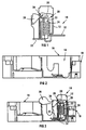
- Figure 1 shows a schematic sectional side view of a trip unit, in accordance with the invention, for a circuit breaker;
- Figure 2 shows, on a reduced scale, a base for a circuit breaker in which the trip unit of Figure 1 is receivable; and
- Figure 3 shows, on a further reduced scale, a base of the circuit breaker with the trip unit mounted therein.
-
- In Figure 1,
reference numeral 10 generally designates a trip unit, in accordance with the invention for a circuit breaker. Thetrip unit 10 is an hydraulic/magnetic trip unit and is modular and removable in nature. Thus, thetrip unit 10 comprises ahousing 12 which is removably receivable in a recess 14 (Figure 2) of abase 16 of a circuit breaker, illustrated schematically at 18. - The
trip unit 10 comprises an hydraulic/magnetic coil andtube assembly 20 arranged in thehousing 12 of thetrip unit 10. Theassembly 20 comprises atube 22 arranged within, and surrounded by, acoil 24. - The
trip unit 10 also includes atripping mechanism 26 having atripping lever 28 which is attracted by thetube 20 for effecting tripping of the circuit breaker, in use. Thetripping lever 28 engages atripping arm 30 arranged externally of thehousing 12 of thetrip unit 10. - The
coil 24 of theassembly 22 has electrical connecting means in the form oflugs 32 connected thereto. Thelugs 32 protrude from thehousing 12. - Electrical connecting means in the form of
electrical terminals 34 are arranged in therecess 14 of thebase 16 of thecircuit breaker 18. Thus, in use, thetrip unit 10 is mounted in therecess 14 of thehousing 16 so that thelugs 32 electrically engage and are connected to theterminals 34. The trip arm 30 of thetripping mechanism 26 of thetrip unit 10 engages an operating mechanism in the form of acradle 36 mounted pivotally on thebase 16 for effecting tripping of thecircuit breaker 18, in use. - Hence, it is an advantage of the invention that an hydraulic/
magnetic circuit breaker 18 is provided which has a removable andmodular trip unit 10. In so doing, the rating of thecircuit breaker 18 can easily and quickly be changed by insertion of theappropriate trip unit 10.
Claims (8)
- An hydraulic/magnetic trip unit for a circuit breaker, the trip unit being modular and removable from the circuit breaker.
- The trip unit as claimed in Claim 1, which includes a housing in which an hydraulic/magnetic coil and tube assembly is housed, with the housing being dimensioned to be receivable in a recess in a base of the circuit breaker.
- The trip unit as claimed in Claim 1 or Claim 2, which includes a tripping mechanism which is engageable, in use, with an operating mechanism of the circuit breaker for effecting tripping of the circuit breaker.
- The trip unit as claimed in Claim 3, which includes an electrical connecting means for connecting the coil and tube assembly of the unit to terminals of the circuit breaker.
- The trip unit as claimed in Claim 4, in which the electrical connecting means is in the form of lugs which protrude from the housing and which, in use, engage with the terminals of the circuit breaker which is located in the base.
- A circuit breaker which includes a modular and removable hydraulic/magnetic trip unit as claimed in any one of the preceding claims, so that its ratings are changeable by inserting therein a unit with an appropriate rating.
- An hydraulic/magnetic trip unit for a circuit breaker, substantially as herein described with reference to the accompanying drawings.
- A circuit breaker, substantially as herein described with reference to the accompanying drawings.
Applications Claiming Priority (2)
| Application Number | Priority Date | Filing Date | Title |
|---|---|---|---|
| ZA982814 | 1998-04-02 | ||
| ZA9802814 | 1998-04-02 |
Publications (2)
| Publication Number | Publication Date |
|---|---|
| EP0948020A2 true EP0948020A2 (en) | 1999-10-06 |
| EP0948020A3 EP0948020A3 (en) | 2000-06-07 |
Family
ID=25586932
Family Applications (1)
| Application Number | Title | Priority Date | Filing Date |
|---|---|---|---|
| EP99302511A Withdrawn EP0948020A3 (en) | 1998-04-02 | 1999-03-31 | A trip unit for an hydraulic/magnetic circuit breaker |
Country Status (2)
| Country | Link |
|---|---|
| EP (1) | EP0948020A3 (en) |
| JP (1) | JPH11329200A (en) |
Families Citing this family (2)
| Publication number | Priority date | Publication date | Assignee | Title |
|---|---|---|---|---|
| US6956452B2 (en) | 2003-09-24 | 2005-10-18 | General Electric Company | Apparatus and method for circuit breaker trip unit adjustment |
| US6980071B2 (en) | 2003-09-24 | 2005-12-27 | General Electric Company | Apparatus and method for circuit breaker trip unit adjustment |
Citations (7)
| Publication number | Priority date | Publication date | Assignee | Title |
|---|---|---|---|---|
| US3729696A (en) * | 1972-04-26 | 1973-04-24 | Heinemann Electric Co | Time delay actuator |
| DE2719053A1 (en) * | 1976-04-28 | 1977-11-10 | Gould Inc | ENGINE STARTER |
| US4129843A (en) * | 1976-10-05 | 1978-12-12 | I-T-E Imperial Corporation | Magnetic trip means for circuit breaker |
| EP0064906A1 (en) * | 1981-05-07 | 1982-11-17 | Merlin Gerin | Multi-pole circuit breaker with an interchangeable thermal-magnetic trip unit |
| US4622530A (en) * | 1983-06-02 | 1986-11-11 | General Electric Company | Circuit breaker assembly for high speed manufacture |
| EP0255955A2 (en) * | 1986-08-07 | 1988-02-17 | Mitsubishi Denki Kabushiki Kaisha | Circuit interrupter |
| WO1996019007A1 (en) * | 1994-12-15 | 1996-06-20 | Siemens Energy & Automation, Inc. | Interface connection for a circuit breaker plug-in trip unit |
-
1999
- 1999-03-31 EP EP99302511A patent/EP0948020A3/en not_active Withdrawn
- 1999-04-01 JP JP11094793A patent/JPH11329200A/en active Pending
Patent Citations (7)
| Publication number | Priority date | Publication date | Assignee | Title |
|---|---|---|---|---|
| US3729696A (en) * | 1972-04-26 | 1973-04-24 | Heinemann Electric Co | Time delay actuator |
| DE2719053A1 (en) * | 1976-04-28 | 1977-11-10 | Gould Inc | ENGINE STARTER |
| US4129843A (en) * | 1976-10-05 | 1978-12-12 | I-T-E Imperial Corporation | Magnetic trip means for circuit breaker |
| EP0064906A1 (en) * | 1981-05-07 | 1982-11-17 | Merlin Gerin | Multi-pole circuit breaker with an interchangeable thermal-magnetic trip unit |
| US4622530A (en) * | 1983-06-02 | 1986-11-11 | General Electric Company | Circuit breaker assembly for high speed manufacture |
| EP0255955A2 (en) * | 1986-08-07 | 1988-02-17 | Mitsubishi Denki Kabushiki Kaisha | Circuit interrupter |
| WO1996019007A1 (en) * | 1994-12-15 | 1996-06-20 | Siemens Energy & Automation, Inc. | Interface connection for a circuit breaker plug-in trip unit |
Also Published As
| Publication number | Publication date |
|---|---|
| EP0948020A3 (en) | 2000-06-07 |
| JPH11329200A (en) | 1999-11-30 |
Similar Documents
| Publication | Publication Date | Title |
|---|---|---|
| US4281359A (en) | Static trip unit for molded case circuit breakers | |
| EP0954002A3 (en) | Thermal magnetic circuit breakers | |
| EP0952650A3 (en) | A switch system of the drawer type | |
| US7986203B2 (en) | Multi-pole armature interlock for circuit breakers | |
| EP1098342A3 (en) | Terminal barrier system for molded case circuit breaker | |
| CA2348620A1 (en) | Parallel contact circuit breaker | |
| US5510759A (en) | Miniature circuit breaker with ground fault electronics supported by stiff conductors for easy assembly | |
| US7034224B2 (en) | Receptacle | |
| US5605224A (en) | Accessory compartment for high ampere-rated circuit breaker | |
| EP1079408A3 (en) | Supplemental trip unit for rotary circuit interrupters | |
| EP0978858A3 (en) | Circuit breaker | |
| EP1077460A3 (en) | Circuit breaker with trip unit mounted tripping latch plunger and latch therefore | |
| EP0948020A2 (en) | A trip unit for an hydraulic/magnetic circuit breaker | |
| EP1098344A3 (en) | Shunt trip device for a molded case circuit breaker | |
| US6853278B2 (en) | Tripping device | |
| US5485134A (en) | Auxiliary switch accessory module unit for high ampere-rated circuit breaker | |
| EP0772050A1 (en) | Improvements in or relating to meter switches | |
| US7281959B2 (en) | Contactor equipped with box terminals | |
| US20060152312A1 (en) | Combination of a switching device and a printed board | |
| GB2071915A (en) | Static trip unit and interlock for circuit breaker | |
| EP1386338B1 (en) | Electric pole for low-voltage power circuit breaker | |
| US1742109A (en) | Electric switch mechanism | |
| US5886600A (en) | Modular thermal magnetic trip unit for rapid circuit interruption | |
| EP1372177A2 (en) | The remote indication of a circuit breaker status | |
| EP0977232A2 (en) | Conductor subhousing for a circuit breaker |
Legal Events
| Date | Code | Title | Description |
|---|---|---|---|
| PUAI | Public reference made under article 153(3) epc to a published international application that has entered the european phase |
Free format text: ORIGINAL CODE: 0009012 |
|
| AK | Designated contracting states |
Kind code of ref document: A2 Designated state(s): AT BE CH CY DE DK ES FI FR GB GR IE IT LI LU MC NL PT SE |
|
| AX | Request for extension of the european patent |
Free format text: AL;LT;LV;MK;RO;SI |
|
| PUAL | Search report despatched |
Free format text: ORIGINAL CODE: 0009013 |
|
| AK | Designated contracting states |
Kind code of ref document: A3 Designated state(s): AT BE CH CY DE DK ES FI FR GB GR IE IT LI LU MC NL PT SE |
|
| AX | Request for extension of the european patent |
Free format text: AL;LT;LV;MK;RO;SI |
|
| RIC1 | Information provided on ipc code assigned before grant |
Free format text: 7H 01H 71/02 A, 7H 01H 71/24 B, 7H 01H 3/24 B, 7H 01H 71/74 B |
|
| AKX | Designation fees paid |
Free format text: AT BE CH CY DE DK ES FI FR GB GR IE IT LI LU MC NL PT SE |
|
| STAA | Information on the status of an ep patent application or granted ep patent |
Free format text: STATUS: THE APPLICATION IS DEEMED TO BE WITHDRAWN |
|
| 18D | Application deemed to be withdrawn |
Effective date: 20001208 |