EP0947869A2 - Optical component - Google Patents
Optical component Download PDFInfo
- Publication number
- EP0947869A2 EP0947869A2 EP99106008A EP99106008A EP0947869A2 EP 0947869 A2 EP0947869 A2 EP 0947869A2 EP 99106008 A EP99106008 A EP 99106008A EP 99106008 A EP99106008 A EP 99106008A EP 0947869 A2 EP0947869 A2 EP 0947869A2
- Authority
- EP
- European Patent Office
- Prior art keywords
- optical component
- cube
- component according
- carrier plate
- shaped body
- Prior art date
- Legal status (The legal status is an assumption and is not a legal conclusion. Google has not performed a legal analysis and makes no representation as to the accuracy of the status listed.)
- Withdrawn
Links
Images


Classifications
-
- G—PHYSICS
- G02—OPTICS
- G02B—OPTICAL ELEMENTS, SYSTEMS OR APPARATUS
- G02B27/00—Optical systems or apparatus not provided for by any of the groups G02B1/00 - G02B26/00, G02B30/00
- G02B27/10—Beam splitting or combining systems
- G02B27/1073—Beam splitting or combining systems characterized by manufacturing or alignment methods
-
- G—PHYSICS
- G02—OPTICS
- G02B—OPTICAL ELEMENTS, SYSTEMS OR APPARATUS
- G02B27/00—Optical systems or apparatus not provided for by any of the groups G02B1/00 - G02B26/00, G02B30/00
- G02B27/10—Beam splitting or combining systems
- G02B27/14—Beam splitting or combining systems operating by reflection only
- G02B27/143—Beam splitting or combining systems operating by reflection only using macroscopically faceted or segmented reflective surfaces
-
- G—PHYSICS
- G02—OPTICS
- G02B—OPTICAL ELEMENTS, SYSTEMS OR APPARATUS
- G02B27/00—Optical systems or apparatus not provided for by any of the groups G02B1/00 - G02B26/00, G02B30/00
- G02B27/10—Beam splitting or combining systems
- G02B27/14—Beam splitting or combining systems operating by reflection only
- G02B27/144—Beam splitting or combining systems operating by reflection only using partially transparent surfaces without spectral selectivity
-
- G—PHYSICS
- G02—OPTICS
- G02B—OPTICAL ELEMENTS, SYSTEMS OR APPARATUS
- G02B7/00—Mountings, adjusting means, or light-tight connections, for optical elements
Definitions
- the invention relates to an optical component according to the preamble of claim 1 and a method for its production after Preamble of claim 13.
- optical connection technology optical communications technology and in optical systems it is necessary to use light beams as carriers of information redirect, distribute and shape emitted light from transmitters and to be directed in parallel.
- Optical information is also used in optical fibers coupled and parallel bundles of light focused on the receiver.
- Palm Springs is known as an optical device that is cube-shaped Body is formed, on the side surfaces of lenses, filters and ⁇ / 4 layers are upset. Beam guidance and beam splitting within the Cube is through a layer running along a side surface diagonal determines whose functionality is already determined during the manufacturing process and cannot be changed afterwards. Especially related to complex optical systems in which a large number of these cube-shaped Individual elements with different functions are used The greatest possible range of variation in the optical properties in the Required in connection with an inexpensive mass production.
- the invention is therefore based on the object of an optical component specify whose optical properties can be varied in a simple manner can and that is inexpensive to manufacture.
- the invention is related to the optical component by the features of claim 1 and in relation to a method by the features of Claim 13 reproduced.
- the other claims included advantageous training and further developments of the invention.
- the particular advantage of the invention is that in a simple manner whose optical properties can be varied.
- the invention Component is therefore versatile and meets the requirements in complex optical systems and can also be inexpensive getting produced.
- the preferred basic shape is a cube-shaped body with diagonal running slot of small width and optionally has at least one curved cube surface. Thanks to its geometric shape, realize complex optical arrangements of the cube-shaped basic form, by putting together several cubes for the desired functionality become.
- the cubes are easy to place and guide elements to adjust against each other. If necessary, besides the preferred one Cube shape can also be realized any other geometrical shape that the in has functionality described the invention.
- a carrier plate By inserting a carrier plate into the slot on its surface
- a mirror or filter layer is applied, the optical properties of the cube and thus its function.
- This Mirror and filter layers can be inexpensively applied to large-area substrates evaporate and with processes of semiconductor technology to small carrier platelets to process. It is also possible to use active optical components, for example LCD elements to be inserted into the slot around polarization beam splitters with switchable direction.
- the cube-shaped optical Component Usually has at least one side surface of the cube-shaped optical Component a spherical or aspherical elevation. This serves the beam formation of the one entering or leaving the optical component Light beam. Only in complex arrangements of several components there is no curved side surface even in cases where a direct light transition with adjacent cubes without one Beam shaping takes place. With versatile possibilities of variation can be so Shaping, collimating or focusing light beams at the same time. Furthermore there is the possibility of light rays in further, in their optical Properties adapted layers, for example to bring cube surfaces to to split them up there.
- the cube surfaces can also have layers, which, in complex systems, has a low-loss light transition of one Ensure cube element in an adjacent one.
- the optical component is a molded part, which as an injection molding process Whole part is manufactured or assembled from individual components and can be fixed.
- the individual components are preferably fixed by gluing or soldering.
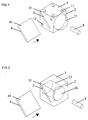
- a convex shape adapted to the beam shape outward geometry 21 can be divergent beams Align in parallel and lead inside the cube.
- FIG. 2 shows an optical component in which cylindrical recess 22 within the cube a plano-convex and with the curvature is introduced into the interior of the lens 23.
- This Arrangement has the particular advantage that the cube surfaces are flat and are related to the effect of a converging lens complex optical systems in which a large number of these cube-shaped Individual elements are guaranteed.
- Hemispherical convex or concave lens systems are particularly found in point transmitters or receivers with a small detection area Application.
- Each cube has a structure or on at least one side surface Marking that makes an exact adjustment on a surface or opposite adjacent cubes or other optical components allowed (Fig. 1).
- knobs 11 in connection with matching recesses 12 attached.
- the arrangement of the knobs 11 and Wells 12 is such that combinations are possible adjacent elements in connection with an exact adjustment.
- Around The nubs 11 and are to ensure optimal beam guidance Wells 12 are usually arranged near the cube corners, so that the Light can pass through the cube surface undisturbed.
- FIG. 4 shows a two-part variant of the one in FIG. 1 that is divided along the slot component shown in one piece, the easy insertion of Carrier plate 4, optionally in guide pins.
- FIG. 5a to d some preferred embodiments are different Top 41 of the carrier plate 4 shown. Except for an all-over, completely reflective coating of the top 41 of a carrier plate 4, can be by a partial coverage 42 of the surface by the cube straight through and the reflected light in any proportion to be changed. To, as shown in Fig. 5a, over the area of the reflective layer 42 an exact percentage of the incoming Obtaining light are corresponding requirements for beam shaping, especially to the beam cross section before or when the light enters the To put cubes. The light distribution can also be done according to FIG All-over, but partially permeable layer 42 take place. The beam distribution then depends on the degree of coverage of the layer on the Carrier plate 4, only on the layer nature. In Fig.
- 5c is for a partially permeable layer shows the reversibility of the beam path in the case of multiple reflection, possibly on additional layers, on the Cube surfaces shape and split the light beam.
- layers 43 on the top 41 of the Carrier plate 4 for the incident light of different wavelengths be selectively partially permeable to wavelength or also to the Polarization state of the incident light act.
- carrier plates 4 are conceivable, the active optical components, for example LCDs included. This allows polarization beam splitters to be used implement switchable direction. With every layer variant, including their Combinations, the functionality of the optical component is diverse Way variable.
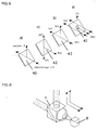
- FIG. 6 shows an example of the beam shaping of a divergent beam from a punctiform transmitter 6.
- the emitted light is through a hemispherical lens directed parallel and through a partially permeable layer split on the carrier plate 4. Both partial beams are parallel aligned on two different cubes.
- the Arrow directions indicate the reversibility of the beam path, in which the light from the cube converges, for example to a receiver falls.
- FIGS. 7 and 8 show two cube halves that over a common edge are connected, so that the final assembly Carrier tiles 4 simply by folding the two halves inside the cube can be included. The entire surface lies when unfolded free to apply an adhesive before the carrier plate is fitted.
Abstract
Description
Die Erfindung bezieht sich auf ein optisches Bauelement nach dem Oberbegriff
des Patentanspruchs 1 und ein Verfahren zu dessen Herstellung nach dem
Oberbegriff des Patentanspruchs 13.The invention relates to an optical component according to the preamble
of
In der optischen Verbindungstechnik, der optischen Nachrichtentechnik und in optischen Systemen ist es erforderlich, Lichtstrahlen als Träger von Information umzulenken, zu verteilen sowie emittiertes Licht aus Sendern zu formen und parallel zu richten. Ebenso werden optische Informationen in Lichtwellenleiter eingekoppelt und parallele Lichtbündel auf Empfänger fokussiert.In optical connection technology, optical communications technology and in optical systems it is necessary to use light beams as carriers of information redirect, distribute and shape emitted light from transmitters and to be directed in parallel. Optical information is also used in optical fibers coupled and parallel bundles of light focused on the receiver.
Aus der Schrift Miyazaki et al. - Tech. Dig. Conf. On Opt. Comp., 16.-19.3.1993, Palm Springs ist ein optisches Bauelement bekannt, das als würfelförmiger Körper ausgebildet ist, auf dessen Seitenflächen Linsen, Filter sowie λ/4-Schichten aufgebracht sind. Eine Strahlführung und Strahlteilung innerhalb des Würfels ist durch eine entlang einer Seitenflächendiagonalen verlaufende Schicht bestimmt, deren Funktionalität bereits beim Herstellungsprozeß festgelegt ist und danach nicht mehr abgeändert werden kann. Besonders im Zusammenhang mit komplexen optischen Systemen, bei denen eine Vielzahl dieser würfelförmigen Einzelelemente unterschiedlicher Funktion zum Einsatz kommen, ist eine möglichst große Variationsbreite in den optischen Eigenschaften im Zusammenhang mit einer kostengünstigen Massenproduktion erforderlich.From the Miyazaki et al. - Tech. Dig. Conf. On Opt. Comp., March 16-19, 1993, Palm Springs is known as an optical device that is cube-shaped Body is formed, on the side surfaces of lenses, filters and λ / 4 layers are upset. Beam guidance and beam splitting within the Cube is through a layer running along a side surface diagonal determines whose functionality is already determined during the manufacturing process and cannot be changed afterwards. Especially related to complex optical systems in which a large number of these cube-shaped Individual elements with different functions are used The greatest possible range of variation in the optical properties in the Required in connection with an inexpensive mass production.
Der Erfindung liegt deshalb die Aufgabe zugrunde, ein optisches Bauelement anzugeben, dessen optische Eigenschaften auf einfache Weise variiert werden können und das kostengünstig herzustellen ist.The invention is therefore based on the object of an optical component specify whose optical properties can be varied in a simple manner can and that is inexpensive to manufacture.
Die Erfindung wird in Bezug auf das optische Bauelement durch die Merkmale
des Patentanspruchs 1 und in Bezug auf ein Verfahren durch die Merkmale des
Patentanspruchs 13 wiedergegeben. Die weiteren Ansprüche enthalten
vorteilhafte Aus- und Weiterbildungen der Erfindung.The invention is related to the optical component by the features
of
Der besondere Vorteil der Erfindung besteht darin, daß auf einfache Weise dessen optische Eigenschaften variiert werden können. Das erfindungsgemäße Bauelement ist dadurch vielseitig einsetzbar und wird den Erfordernissen in komplexen optischen Systemen gerecht und kann zudem kostengünstig hergestellt werden.The particular advantage of the invention is that in a simple manner whose optical properties can be varied. The invention Component is therefore versatile and meets the requirements in complex optical systems and can also be inexpensive getting produced.
Die bevorzugte Grundform ist ein würfelförmiger Körper mit diagonal verlaufendem Schlitz geringer Breite und weist gegebenenfalls mindestens eine gekrümmten Würfelfläche auf. Durch seine geometrische Form lassen sich aus der würfelförmigen Grundform komplexe optische Anordnungen realisieren, indem mehrere Würfel für die gewünschte Funktionalität zusammengesetzt werden. Die Würfel sind durch Führungselemente leicht zu plazieren und gegeneinander zu justieren. Falls erforderlich, kann außer der bevorzugten Würfelform auch jede andere geometrische Form realisiert werden, welche die in der Erfindung beschriebene Funktionalität aufweist.The preferred basic shape is a cube-shaped body with diagonal running slot of small width and optionally has at least one curved cube surface. Thanks to its geometric shape, realize complex optical arrangements of the cube-shaped basic form, by putting together several cubes for the desired functionality become. The cubes are easy to place and guide elements to adjust against each other. If necessary, besides the preferred one Cube shape can also be realized any other geometrical shape that the in has functionality described the invention.
Durch das Einsetzen eines Trägerplättchens in den Schlitz, auf dessen Oberfläche beispielsweise eine Spiegel- oder Filterschicht aufgebracht ist, werden die optischen Eigenschaften des Würfels und so dessen Funktion festgelegt. Diese Spiegel- und Filterschichten lassen sich kostengünstig auf großflächige Substrate aufdampfen und mit Verfahren der Halbleitertechnik zu kleinen Trägerplättchen verarbeiten. Zudem ist es auch möglich, aktive optische Bauelemente, beispielsweise LCD-Elemente, in den Schlitz einzubringen um Polarisations-Strahlteiler mit schaltbarer Richtung zu realisieren.By inserting a carrier plate into the slot on its surface For example, a mirror or filter layer is applied, the optical properties of the cube and thus its function. This Mirror and filter layers can be inexpensively applied to large-area substrates evaporate and with processes of semiconductor technology to small carrier platelets to process. It is also possible to use active optical components, for example LCD elements to be inserted into the slot around polarization beam splitters with switchable direction.
Üblicherweise besitzt mindestens eine Seitenfläche des würfelförmigen optischen Bauelements zentrisch eine sphärische oder asphärische Erhebung. Diese dient der Strahlformung des in das optische Bauelement ein- oder austretenden Lichtstrahls. Lediglich in komplexen Anordnungen mehrerer Bauelemente wird auf eine gekrümmte Seitenfläche auch in den Fällen verzichtet, bei denen ein direkter Lichtübergang bei aneinandergrenzenden Würfeln ohne eine Strahlformung stattfindet. Mit vielseitiger Variationsmöglichkeit lassen sich so Lichtstrahlen gleichzeitig formen, kollimieren oder fokussieren. Außerdem besteht die Möglichkeit, Lichtstrahlen in weitere, in ihren optischen Eigenschaften angepaßte Ebenen, beispielsweise Würfelflächen zu bringen, um diese dort aufzuteilen. Auch können die Würfeloberflächen Schichten aufweisen, die bei komplexen Systemen einen verlustarmen Lichtübergang von einem Würfelelement in ein benachbartes gewährleisten.Usually has at least one side surface of the cube-shaped optical Component a spherical or aspherical elevation. This serves the beam formation of the one entering or leaving the optical component Light beam. Only in complex arrangements of several components there is no curved side surface even in cases where a direct light transition with adjacent cubes without one Beam shaping takes place. With versatile possibilities of variation can be so Shaping, collimating or focusing light beams at the same time. Furthermore there is the possibility of light rays in further, in their optical Properties adapted layers, for example to bring cube surfaces to to split them up there. The cube surfaces can also have layers, which, in complex systems, has a low-loss light transition of one Ensure cube element in an adjacent one.
Das optische Bauelement ist ein Formteil, das mittels Spritzgußverfahren als Gesamtteil hergestellt wird oder aus einzelnen Komponenten zusammengefügt und fixiert werden kann. Die Fixierung der Einzelkomponenten erfolgt bevorzugt durch Verkleben oder Löten.The optical component is a molded part, which as an injection molding process Whole part is manufactured or assembled from individual components and can be fixed. The individual components are preferably fixed by gluing or soldering.
Im folgenden wird die Erfindung anhand von vorteilhaften Ausführungsbeispielen unter Bezugnahme auf schematische Zeichnungen in den folgenden Figuren näher erläutert. Es zeigen:
- Fig. 1
- Optisches Bauelement als würfelförmiger Körper mit konvexer Seitenfläche,
- Fig. 2
- Optisches Bauelement mit konvexer, ins Würfelinnere gerichteter Seitenfläche,
- Fig. 3
- Optisches Bauelement mit konkaver Seitenfläche,
- Fig. 4
- Optisches Bauelement mit durchgehendem Schlitz,
- Fig. 5a-d
- Ausführungsformen bei Trägerplättchen,
- Fig. 6
- Funktionsweise eines optischen Bauelements,
- Fig. 7
- Vorteilhafte Ausgangsformen nach Spritzguß-Herstellungsverfahren.
- Fig. 8
- Spritzguß-Ausgangsform mit innenliegendem Trägerplättchen.
- Fig. 1
- Optical component as a cube-shaped body with a convex side surface,
- Fig. 2
- Optical component with a convex side surface facing the inside of the cube,
- Fig. 3
- Optical component with a concave side surface,
- Fig. 4
- Optical component with continuous slot,
- 5a-d
- Embodiments of carrier platelets,
- Fig. 6
- How an optical component works,
- Fig. 7
- Advantageous starting forms after injection molding manufacturing processes.
- Fig. 8
- Injection molded starting form with internal carrier plate.
Im Ausführungsbeispiel gemäß Fig. 1 wird ein optisches Bauelement in der
bevorzugten Ausführungsform eines würfelförmigen Körpers 1 dargestellt.In the embodiment shown in FIG. 1, an optical component in the
preferred embodiment of a cube-shaped
Im Inneren des Würfels verläuft ein Schlitz 3, in den ein die optischen
Eigenschaften bestimmendes Trägerplättchen 4 eingebracht wird. Die optischen
Eigenschaften werden durch dünne Schichten auf der Oberseite 41 des
Trägerplättchens 4 festgelegt. Im eingebauten Zustand verläuft die Oberseite 41
des Trägerplättchens 4 mit der funktionsbestimmenden Schicht entlang der
Seitenflächendiagonalen 31. Dadurch verläuft der Schlitz 3 etwas azentrisch,
jedoch parallel zu der Seitenflächendiagonalen 31. Die zentrische Anordnung der
funktionsbestimmenden Schicht nutzt die Symmetrieelemente des Würfels, mit
denen sich auch komplexe Anordnungen, bestehend aus einer Vielzahl einzelner
Würfel aufbauen lassen.Inside the cube there is a
Zur Strahlformung des in den Würfel eintretenden Lichts, das beispielsweise aus
einem Lichtwellenleiter 5 oder Sender 6 stammt, ist zumindest eine Seitenfläche
2 gekrümmt ausgebildet. Durch eine der Strahlform angepaßte konvexe, also
nach außen gerichtete Geometrie 21 lassen sich divergente Strahlenbündel
parallel richten und im Würfelinneren führen.For shaping the beam of light entering the cube, for example from
is an
Alternativ dazu zeigt Fig.2 ein optisches Bauelement, bei dem in eine
zylinderförmige Aussparung 22 innerhalb des Würfels eine plankonvexe und mit
der Krümmung ins Würfelinnere gerichtete Linse 23 eingebracht ist. Diese
Anordnung hat den besonderen Vorteil, daß die Würfelflächen eben ausgebildet
sind und sich so die Wirkung einer Sammellinse im Zusammenhang mit
komplexen optischen Systemen, bei denen eine Vielzahl dieser würfelförmigen
Einzelelemente zum Einsatz kommen gewährleistet ist.As an alternative to this, FIG. 2 shows an optical component in which
In gleicher Weise können Seitenflächen, die konkav ins Innere des Würfels
orientiert 24 sind, konvergente Strahlenbündel parallel richten (Fig. 3). In the same way, side faces that are concave inside the
Halbkugelförmige konvexe oder konkave Linsensysteme finden besonders bei punktförmigen Sendern oder Empfängern mit Kleiner Detektionsfläche Anwendung.Hemispherical convex or concave lens systems are particularly found in point transmitters or receivers with a small detection area Application.
Jeder Würfel besitzt an zumindest einer Seitenfläche eine Struktur oder Markierung, die eine exakte Justage aufeiner Unterlage oder gegenüber benachbarten Würfels oder anderen optischen Bauelementen erlaubt (Fig. 1).Each cube has a structure or on at least one side surface Marking that makes an exact adjustment on a surface or opposite adjacent cubes or other optical components allowed (Fig. 1).
Hierzu werden aufder Seitenfläche beispielsweise Noppen 11 in Verbindung mit
dazu passenden Vertiefungen 12 angebracht. Die Anordnung der Noppen 11 und
Vertiefungen 12 ist derart, daß sich Kombinationsmöglichkeiten gegenüber
benachbarten Elementen in Verbindung mit einer exakten Justage ergeben. Um
eine optimale Strahlführung zu gewährleisten, sind die Noppen 11 und
Vertiefungen 12 üblicherweise nahe der Würfelecken angeordnet, so daß das
Licht die Würfeloberfläche ungestört passieren kann.For this purpose, for example, knobs 11 in connection with
matching
Fig. 4 zeigt eine entlang dem Schlitz geteilte zweiteilige Variante des in Fig. 1
einteilig dargestellten Bauelements, die ein einfaches Einsetzen des
Trägerplättchens 4, gegebenenfalls in Führungsstifte ermöglicht.FIG. 4 shows a two-part variant of the one in FIG. 1 that is divided along the slot
component shown in one piece, the easy insertion of
In Fig. 5a bis d sind einige bevorzugte Ausführungsformen unterschiedlicher
Oberseiten 41 der Trägerplättchen 4 dargestellt. Außer einer ganzflächigen,
vollständig reflektierenden Beschichtung der Oberseite 41 eines Trägerplättchens
4, kann durch eine Teilbedeckung 42 der Oberfläche das durch den Würfel
geradlinig hindurchtretende und das reflektierte Licht zu beliebigen Anteilen
verändert werden. Um, wie in der Fig. 5a dargestellt, über den Flächenanteil der
reflektierenden Schicht 42 eine exakte prozentuale Aufteilung des eintretenden
Lichts zu erhalten, sind entsprechende Anforderungen an die Strahlformung,
insbesondere an den Strahlquerschnitt vor oder beim Eintritt des Lichts in den
Würfel zu stellen. Die Lichtaufteilung kann auch gemäß Fig. 5b durch eine
ganzflächige, jedoch teildurchlässige Schicht 42 erfolgen. Die Strahlaufteilung
hängt dann, unabhängig vom Bedeckungsgrad der Schicht auf dem
Trägerplättchen 4, lediglich von der Schichtbeschaffenheit ab. In Fig. 5c ist für
eine teildurchlässige Schicht die Umkehrbarkeit des Strahlweges dargestellt, der
bei Mehrfachreflexion, gegebenenfalls an zusätzlichen Schichten, auf den
Würfeloberflächen den Lichtstrahl formt und teilt. Ebenso können auch, wie in
Fig. 5d für zwei Wellenlängen dargestellt, Schichten 43 auf der Oberseite 41 des
Trägerplättchens 4 für das eingestrahlte Licht unterschiedlicher Wellenlänge
wellenlängenselektiv teildurchlässig beschaffen sein oder auch auf den
Polarisationszustand des eingestrahlten Lichts wirken.5a to d, some preferred embodiments are
Zudem sind Trägerplättchen 4 denkbar, die aktive optische Komponenten,
beispielweise LCD's enthalten. Dadurch lassen sich Polarisations- Strahlteiler mit
schaltbarer Richtung realisieren. Mit jede Schichtvariante, einschließlich deren
Kombinationen, ist die Funktionalität des optischen Bauelements in vielfältiger
Weise variabel.In addition,
Gerade im Zusammenhang mit komplexen optischen Systemen, bei denen eine Vielzahl würfelförmiger Einzelelemente angeordnet werden, ist eine große Variationsbreite in den optischen Eigenschaften im Zusammenhang mit einer kostengünstigen Massenproduktion gewährleistet.Especially in connection with complex optical systems, in which one A large number of cube-shaped individual elements is arranged Variation in the optical properties in connection with a guaranteed cost-effective mass production.
Fig. 6 zeigt exemplarisch die Strahlformung eines divergenten Strahlenbündels
aus einem punktförmigen Sender 6. Das emittierte Licht wird durch eine
halbkugelförmige Linse parallel gerichtet und durch eine teildurchlässige Schicht
auf dem Trägerplättchen 4 aufgespalten. Beide Teilstrahlen treten parallel
gerichtet an zwei unterschiedlichen Würfelflächen wieder aus. Die
Pfeilrichtungen deuten auf die Umkehrbarkeit des Strahlweges hin, bei der das
vom Würfel stammende Licht konvergent, beispielsweise auf einen Empfänger
fällt. 6 shows an example of the beam shaping of a divergent beam
from a punctiform transmitter 6. The emitted light is through a
hemispherical lens directed parallel and through a partially permeable layer
split on the
Außer der in Fig. 4 dargestellten, entlang dem Schlitz geteilten zweiteiligen
Variante des Bauelements, zeigen die Fig. 7 und 8 zwei Würfelhälften, die über
eine gemeinsame Kante verbunden sind, so daß bei der endgültigen Montage das
Trägerplättchen 4 allein durch Umklappen der beiden Hälften im Würfelinneren
eingeschlossen werden kann. Im aufgefalteten Zustand liegt die gesamte Fläche
zum Aufbringen eines Klebers frei, bevor das Trägerplättchen eingepaßt wird.Except for the two-part split along the slot shown in Fig. 4
Variant of the component, FIGS. 7 and 8 show two cube halves that over
a common edge are connected, so that the final
Auch ein Verlöten der Einzelteile wäre denkbar. Beide in Fig. 7 und 8 dargestellte Ausgangsformen lassen sich als Massenprodukt mit Hilfe des Spritzgußverfahrens herstellen. Fig. 7 beinhaltet eine zur Oberfläche des Würfels offene Schlitzform, in die ein planparalleles Trägerplättchen auch noch nach Zusammenfügen der Würfelhälften eingeführt werden kann. Bei nachträglichem Einführen des Trägerplättchen ist auch ein etwas keilförmiges Trägerplättchen mit entsprechend angepaßtem Schlitz, der sich ins Würfelinnere verjüngt von Vorteil. Andere Varianten der Trägerplättchen sind in Fig. 8 beispielhaft dargestellt. Dort besitzt das Trägerplättchen eine dachförmige Gestalt, das in diesem Fall auch strahlformende Elemente der Würfeloberfläche enthält. Die funktionsbestimmende Schicht ist in diesem Falle auf der Unterseite aufgebracht.Soldering the individual parts would also be conceivable. Both in Figs. 7 and 8 Starting forms shown can be mass-produced using the Manufacture injection molding process. 7 includes one to the surface of the cube open slot shape, into which a plane-parallel carrier plate also extends Merging the cube halves can be introduced. With subsequent Inserting the carrier plate is also a somewhat wedge-shaped carrier plate with a correspondingly adapted slot that tapers into the inside of the cube Advantage. Other variants of the carrier platelets are exemplary in FIG. 8 shown. There the carrier plate has a roof-like shape, which in this case also contains beam-shaping elements of the cube surface. The In this case, the function-determining layer is applied to the underside.
Claims (15)
daß der würfelförmige Körper (1) einen Schlitz (3) enthält, in den ein die optischen Eigenschaften bestimmendes Trägerplättchen (4) eingebracht ist.Optical component, preferably designed as a cube-shaped body (1), characterized in that
that the cube-shaped body (1) contains a slot (3) into which a carrier plate (4) determining the optical properties is introduced.
Applications Claiming Priority (2)
| Application Number | Priority Date | Filing Date | Title |
|---|---|---|---|
| DE1998114969 DE19814969A1 (en) | 1998-04-03 | 1998-04-03 | Optical component |
| DE19814969 | 1998-04-03 |
Publications (2)
| Publication Number | Publication Date |
|---|---|
| EP0947869A2 true EP0947869A2 (en) | 1999-10-06 |
| EP0947869A3 EP0947869A3 (en) | 2002-02-20 |
Family
ID=7863489
Family Applications (1)
| Application Number | Title | Priority Date | Filing Date |
|---|---|---|---|
| EP99106008A Withdrawn EP0947869A3 (en) | 1998-04-03 | 1999-03-25 | Optical component |
Country Status (2)
| Country | Link |
|---|---|
| EP (1) | EP0947869A3 (en) |
| DE (1) | DE19814969A1 (en) |
Cited By (4)
| Publication number | Priority date | Publication date | Assignee | Title |
|---|---|---|---|---|
| WO2005001515A1 (en) * | 2003-06-23 | 2005-01-06 | Siemens Aktiengesellschaft | Optoelectronic coupler comprising a one-piece optical tube |
| EP1696254A1 (en) * | 2005-02-28 | 2006-08-30 | Samsung Electro-Mechanics Co., Ltd. | Camera module |
| WO2007016199A2 (en) * | 2005-07-29 | 2007-02-08 | 3M Innovative Properties Company | Polarizing beam splitter with lens function |
| US7362507B2 (en) | 2005-07-29 | 2008-04-22 | 3M Innovative Properties Company | Polarizing beam splitter |
Families Citing this family (1)
| Publication number | Priority date | Publication date | Assignee | Title |
|---|---|---|---|---|
| DE202017001743U1 (en) | 2017-03-31 | 2017-05-08 | Siemens Aktiengesellschaft | Gas analyzer |
Citations (9)
| Publication number | Priority date | Publication date | Assignee | Title |
|---|---|---|---|---|
| US1662693A (en) * | 1925-01-26 | 1928-03-13 | Astafiev Michael | Optical system |
| DE461403C (en) * | 1924-03-22 | 1928-06-19 | Aron Hamburger | Prism block for splitting the light rays in color photographs |
| US3874779A (en) * | 1973-07-05 | 1975-04-01 | Corning Glass Works | Variable ratio light coupler |
| EP0197841A1 (en) * | 1985-03-29 | 1986-10-15 | Socapex | Optical duplexer for integrated semi-permanent optical connection |
| US4641926A (en) * | 1982-07-14 | 1987-02-10 | Fujitsu Limited | Polarizing element |
| EP0463779A1 (en) * | 1990-06-16 | 1992-01-02 | Gec-Marconi Avionics (Holdings) Limited | Fibre optic waveguide beam splitter |
| DE19616834A1 (en) * | 1995-04-28 | 1996-10-31 | Asahi Seimitsu Kk | Optical beam splitter prism |
| DE19539726A1 (en) * | 1995-10-25 | 1997-05-07 | Agfa Gevaert Ag | Image signal detection device for photographic printer |
| EP0901023A2 (en) * | 1997-09-05 | 1999-03-10 | Nec Corporation | Optomechanical components for use as optical interconnects |
-
1998
- 1998-04-03 DE DE1998114969 patent/DE19814969A1/en not_active Withdrawn
-
1999
- 1999-03-25 EP EP99106008A patent/EP0947869A3/en not_active Withdrawn
Patent Citations (9)
| Publication number | Priority date | Publication date | Assignee | Title |
|---|---|---|---|---|
| DE461403C (en) * | 1924-03-22 | 1928-06-19 | Aron Hamburger | Prism block for splitting the light rays in color photographs |
| US1662693A (en) * | 1925-01-26 | 1928-03-13 | Astafiev Michael | Optical system |
| US3874779A (en) * | 1973-07-05 | 1975-04-01 | Corning Glass Works | Variable ratio light coupler |
| US4641926A (en) * | 1982-07-14 | 1987-02-10 | Fujitsu Limited | Polarizing element |
| EP0197841A1 (en) * | 1985-03-29 | 1986-10-15 | Socapex | Optical duplexer for integrated semi-permanent optical connection |
| EP0463779A1 (en) * | 1990-06-16 | 1992-01-02 | Gec-Marconi Avionics (Holdings) Limited | Fibre optic waveguide beam splitter |
| DE19616834A1 (en) * | 1995-04-28 | 1996-10-31 | Asahi Seimitsu Kk | Optical beam splitter prism |
| DE19539726A1 (en) * | 1995-10-25 | 1997-05-07 | Agfa Gevaert Ag | Image signal detection device for photographic printer |
| EP0901023A2 (en) * | 1997-09-05 | 1999-03-10 | Nec Corporation | Optomechanical components for use as optical interconnects |
Cited By (6)
| Publication number | Priority date | Publication date | Assignee | Title |
|---|---|---|---|---|
| WO2005001515A1 (en) * | 2003-06-23 | 2005-01-06 | Siemens Aktiengesellschaft | Optoelectronic coupler comprising a one-piece optical tube |
| EP1696254A1 (en) * | 2005-02-28 | 2006-08-30 | Samsung Electro-Mechanics Co., Ltd. | Camera module |
| WO2007016199A2 (en) * | 2005-07-29 | 2007-02-08 | 3M Innovative Properties Company | Polarizing beam splitter with lens function |
| WO2007016199A3 (en) * | 2005-07-29 | 2007-04-19 | 3M Innovative Properties Co | Polarizing beam splitter with lens function |
| US7362507B2 (en) | 2005-07-29 | 2008-04-22 | 3M Innovative Properties Company | Polarizing beam splitter |
| US7529029B2 (en) | 2005-07-29 | 2009-05-05 | 3M Innovative Properties Company | Polarizing beam splitter |
Also Published As
| Publication number | Publication date |
|---|---|
| DE19814969A1 (en) | 1999-10-07 |
| EP0947869A3 (en) | 2002-02-20 |
Similar Documents
| Publication | Publication Date | Title |
|---|---|---|
| DE69815860T2 (en) | INTEGRATED RADIATOR AND ITS USE | |
| DE3803529C2 (en) | ||
| EP2120025B1 (en) | Optical sensor device for detecting ambient light | |
| EP0927376B1 (en) | A fiber optic circuit switch and a process for its production | |
| DE69908325T2 (en) | INTEGRATED MICROOPTIC SYSTEMS | |
| DE19610881B4 (en) | Microsystem module | |
| WO2007036064A1 (en) | Optical device for led light sources | |
| DE10043985A1 (en) | Optical modifier and manufacturing method therefor | |
| EP3130950A1 (en) | Beam deflection element and optical construction element with beam deflection element | |
| EP1361460B1 (en) | Triple reflector and wide angle sensor system comprising the same | |
| DE10124370A1 (en) | Optical element, comprising a transparent base member with reflecting surfaces which are structured and formed to reflect some of the light leaving | |
| EP1373966B1 (en) | Beam shaping device, system for launching a light beam into an optical fibber, and beam rotation unit for such a beam shaping device or such a system | |
| DE4428704C2 (en) | Line-of-sight guidance system for high-power laser beams | |
| EP0723670B1 (en) | Process for manufacturing prisms, in particular microprisms and beam splitters | |
| DE10260628A1 (en) | collimator | |
| DE10220378A1 (en) | Laser light source device | |
| DE10336104A1 (en) | Photoelectric sensor for use in automated production has a beam projector with a beam deflection angle adjuster comprising a pivoting plane parallel glass plate and a displaceable projection lens | |
| EP3497495A1 (en) | Photonic component and method for producing same | |
| DE112019002367T5 (en) | Meta-surface structure and method for producing a meta-surface structure | |
| EP0807842B1 (en) | Optical arrangement with diffractive optical element | |
| EP0947869A2 (en) | Optical component | |
| DE19834090A1 (en) | Optoelectronic transmitter and receiver unit | |
| DE102019210750B4 (en) | METHOD FOR PRODUCING AN ARRANGEMENT WITH A SUBSTRATE AND TWO COMPONENTS WITH OPTICAL WAVE GUIDES | |
| DE3010971C2 (en) | ||
| DE10013261B4 (en) | Micromechanically produced optical beam splitter |
Legal Events
| Date | Code | Title | Description |
|---|---|---|---|
| PUAI | Public reference made under article 153(3) epc to a published international application that has entered the european phase |
Free format text: ORIGINAL CODE: 0009012 |
|
| AK | Designated contracting states |
Kind code of ref document: A2 Designated state(s): AT BE CH CY DE DK ES FI FR GB GR IE IT LI LU MC NL PT SE Kind code of ref document: A2 Designated state(s): DE FR GB |
|
| AX | Request for extension of the european patent |
Free format text: AL;LT;LV;MK;RO;SI |
|
| PUAL | Search report despatched |
Free format text: ORIGINAL CODE: 0009013 |
|
| AK | Designated contracting states |
Kind code of ref document: A3 Designated state(s): AT BE CH CY DE DK ES FI FR GB GR IE IT LI LU MC NL PT SE |
|
| AX | Request for extension of the european patent |
Free format text: AL;LT;LV;MK;RO;SI |
|
| RIC1 | Information provided on ipc code assigned before grant |
Free format text: 7G 02B 7/00 A, 7G 02B 7/182 B, 7G 02B 27/10 B |
|
| 17P | Request for examination filed |
Effective date: 20020307 |
|
| AKX | Designation fees paid |
Free format text: DE FR GB |
|
| STAA | Information on the status of an ep patent application or granted ep patent |
Free format text: STATUS: THE APPLICATION IS DEEMED TO BE WITHDRAWN |
|
| 18D | Application deemed to be withdrawn |
Effective date: 20041001 |