EP0947645B1 - A pneumatic structure - Google Patents
A pneumatic structure Download PDFInfo
- Publication number
- EP0947645B1 EP0947645B1 EP98122580A EP98122580A EP0947645B1 EP 0947645 B1 EP0947645 B1 EP 0947645B1 EP 98122580 A EP98122580 A EP 98122580A EP 98122580 A EP98122580 A EP 98122580A EP 0947645 B1 EP0947645 B1 EP 0947645B1
- Authority
- EP
- European Patent Office
- Prior art keywords
- pneumatic
- pneumatic structure
- wall
- structure according
- screens
- Prior art date
- Legal status (The legal status is an assumption and is not a legal conclusion. Google has not performed a legal analysis and makes no representation as to the accuracy of the status listed.)
- Expired - Lifetime
Links
Images


Classifications
-
- E—FIXED CONSTRUCTIONS
- E04—BUILDING
- E04H—BUILDINGS OR LIKE STRUCTURES FOR PARTICULAR PURPOSES; SWIMMING OR SPLASH BATHS OR POOLS; MASTS; FENCING; TENTS OR CANOPIES, IN GENERAL
- E04H15/00—Tents or canopies, in general
- E04H15/20—Tents or canopies, in general inflatable, e.g. shaped, strengthened or supported by fluid pressure
- E04H2015/202—Tents or canopies, in general inflatable, e.g. shaped, strengthened or supported by fluid pressure with inflatable panels, without inflatable tubular framework
- E04H2015/204—Tents or canopies, in general inflatable, e.g. shaped, strengthened or supported by fluid pressure with inflatable panels, without inflatable tubular framework made from contiguous inflatable tubes
-
- E—FIXED CONSTRUCTIONS
- E04—BUILDING
- E04H—BUILDINGS OR LIKE STRUCTURES FOR PARTICULAR PURPOSES; SWIMMING OR SPLASH BATHS OR POOLS; MASTS; FENCING; TENTS OR CANOPIES, IN GENERAL
- E04H15/00—Tents or canopies, in general
- E04H15/20—Tents or canopies, in general inflatable, e.g. shaped, strengthened or supported by fluid pressure
- E04H2015/202—Tents or canopies, in general inflatable, e.g. shaped, strengthened or supported by fluid pressure with inflatable panels, without inflatable tubular framework
- E04H2015/205—Tents or canopies, in general inflatable, e.g. shaped, strengthened or supported by fluid pressure with inflatable panels, without inflatable tubular framework made from two sheets with intermediate spacer means
-
- E—FIXED CONSTRUCTIONS
- E04—BUILDING
- E04H—BUILDINGS OR LIKE STRUCTURES FOR PARTICULAR PURPOSES; SWIMMING OR SPLASH BATHS OR POOLS; MASTS; FENCING; TENTS OR CANOPIES, IN GENERAL
- E04H15/00—Tents or canopies, in general
- E04H15/20—Tents or canopies, in general inflatable, e.g. shaped, strengthened or supported by fluid pressure
- E04H2015/206—Details of inflation devices, e.g. valves, connections to fluid pressure source
Definitions
- the invention relates to a pneumatic structure in the form of a barrel roof which is adapted to be provided over the entirety or a portion of a working or living space, such as a work site for maintenance or painting a watercraft, a construction site, a temporary site for an exhibition, or a stadium, and permits activity even under rain or snow.
- a pneumatic structure which is light and is capable of bearing a wind or snow load.
- Japanese Unexamined Patent Publication (Kokai) No. 9-144382 which was filed on June 4, 1997 by the applicant, describes a pneumatic structure for temporary use.
- the pneumatic structure includes outer and inner sheets or membranes connected by reinforcement sheets or membranes in the form of ribs, which define a plurality of air compartments into which compressed air is introduced to inflate the structure.
- the partition walls include openings which allow air to flow between the air compartments.
- the pneumatic structure of the prior art is capable of protecting a working space from rain, but heavy snow and gales, for example winds over 10 m/sec collapse the pneumatic structure. This problem is serious in case of large structure since the larger the structure, the larger the snow or wind load on the structure.
- DE 1 961 523 A discloses a pneumatic structure according to the preamble of claim 1.
- the invention is directed to solve the problems of the prior art, and to provide a pneumatic structure improved to facilitate transportation, installation, and deinstallation even if the size of the structure is increased.
- the objective of the invention is also to provide a pneumatic structure improved to increase its strength against snow or wind loads.
- the invention provides a pneumatic structure in the form of a barrel roof which has openings at the opposite ends thereof.
- the pneumatic structure comprises outer and inner walls of a sheet or membrane material connected by a plurality of partition walls of a sheet or membrane material in the form of ribs provided therebetween to define a plurality of air compartments in the form of ribs between the outer and inner walls; the partition walls including a plurality of openings for fluid communication between adjacent air compartments.
- a pneumatic structure assembly in the form of a barrel roof which has openings at the opposite ends thereof.
- the pneumatic structure assembly comprises at least two pneumatic structure portions which are connected to each other at the ends of the respective structure portions.
- Each of the pneumatic structure comprises outer and inner walls of a sheet or membrane material connected by a plurality of partition walls in the form of ribs provided therebetween to define a plurality of air compartments in the form of ribs between the outer and inner walls; and an abutment, provided at an end of the structure portion, for contacting the abutment portion of the other pneumatic structure portion when the two pneumatic structure portions are connected to each other.
- the partition walls including a plurality of openings for fluid communication between adjacent air compartments.
- the pneumatic structure has specific dimensions defined as follows. 1.20 ⁇ b / a ⁇ 1.35 1.10 ⁇ d / c ⁇ 1.35 0.2 ⁇ c / a ⁇ 0.5
- a pneumatic structure 10 comprises outer and inner walls 12 and 14 which are connected by a plurality of partition walls 16 in the form of ribs to define a plurality of air compartments 20 (refer to Figure 4).
- the partition walls 16 include openings 18 to allow air flow between the air compartments 20.
- the pneumatic structure 10 further includes screens 22 and abutments 28 at the both ends of the structure 10.
- An air source 26 including for example a fan, a blower or a compressor, supplies compressed air into the air compartments through conduit 26a and at least one of a plurality of ports 24 to inflate the structure 10.
- Providing the air source 26 with a heater (not shown) to supply hot air into the air compartments can melt snow accumulated on the pneumatic structure 10.
- the outer, inner and partition walls comprise a sheet or membrane material of a woven fabric or knitted fabric from a high-tenacity fiber, such as a polyester fiber, a polyamide fiber, a aramid fiber, a carbon fiber, a polyolefine fiber, or a polyacrylate fiber, and preferably a polyester fiber, and a aramid fiber.
- a resin material such as polyurethane or vinyl chloride, or a rubber material such as acrylic rubber or fluoro rubber, to provide impermeability as described below.
- the sheet or membrane material has a density which falls within a range of 30 - 200 g/m 2 , preferably 30 - 50 g/m 2 .
- the density larger than 200 g/m 2 , the weight of the pneumatic structure increases and the relatively high rigidity of the sheet impair the handling of the structure.
- the strength of the sheet material is too low for the structure.
- the density of the sheet or membrane material is preferably selected within a range of 30 - 50 g/m 2 to reduce the weight of the structure.
- the air permeability of the sheet of membrane material is selected within a range of 0.1 cc/sec-m 2 or less, preferably 0.02 cc/sec-m 2 or less. In the most preferable case, an impermeable sheet material is used.
- the permeability is in compliance with "JIS L1096 Test Method For General Fabric", in which air flow per unit area and time through a sample fabric per is determined under differential pressure of 1.27 cm-Hg.
- the partition walls 16 in the form of ribs, extend parallel to each other between the outer and inner walls 12 and 14 at an interval of 20 - 100 cm.
- the partition walls 16 are connected to the outer and inner walls 12 and 14 to reinforce the pneumatic structure 10.
- the partition walls 16 include a plurality of openings 18 which allow an air flow between the air compartments.
- the openings 18 have a total area which is 1/400 - 1/2 of that of the partition walls 16.
- the upper limit of the area of the openings 18 is determined by the strength of partition walls 16.
- the lower limit of the total area of the openings 18 is determined by air flow between the air compartments, that is the time required by charge and discharge air into and from the structure.
- the preferable shape of the openings 18 is a circle or an ellipse.
- the pneumatic structure 10 has specific dimensions as shown in Figure 2.
- "a” is the maximum opening width
- "b” is the total width
- “c” is the effective height (between ground and the maximum height of the inner wall 14)
- “d” is the total height (between ground and the maximum height of the outer wall 14)
- “ru” is the radius of curvature of the outer wall at the top of the structure
- “rm” is also radius of curvature of the outer wall at the middle point along the outer wall between the top and the bottom of the structure.
- the ratio of the total width "b" and the maximum opening width "a", that is b/a preferably falls in a range of 1.20 - 1.35.
- the pneumatic structure which has the ratio b/a less than 1.20 tends to collapse due to snow or wind load.
- the ratio b/a is more than 1.35, the effective area of the pneumatic structure 10 usable for working is notable reduced relative to the total installed area, which results in an economic problem.
- the ratio of the total height "d" and the effective height "c", that is d/c preferably falls in a range of 1.10 - 1.35.
- the pneumatic structure which has a ratio d/c of less than 1.10 tends to collapse due to a load such as a snow or wind load.
- a ratio d/c of more than 1.35 increases the amount of the material and thus the weight of the pneumatic structure to deteriorate the handling thereof.
- the ratio d/c more than 1.35 increases the area of the side wall of the pneumatic structure, which receives wind pressure, so that the structure can easily collapse under the wind load.
- the ratio of the maximum opening width "a" and the effective height, that is c/a preferably falls in a range of 0.2 - 0.5.
- the ratio c/a less than 0.2 reduces the working space provided by the structure, and flattens the pneumatic structure to accumulate snow on the top of the structure and to make it difficult to remove snow on the top.
- the ratio more than 0.5 increases a wind load received by the structure, which makes the structure tend to collapse.
- the ratio of the radius of curvature ru at the top of the structure and radius of curvature rm at the middle point, that is ru/rm preferably falls in a range of 1.15 - 1.30. If the ratio ru/rm is smaller than 1.15, a wind load initially makes corrugations in the outer wall at the middle point. The larger the wind, the larger are the corrugations generated in the outer wall which will lead to the collapse of the structure. In order to prevent this, reinforcement is required for the structure. On the other hand, a ratio ru/rm of larger than 1.30 increases the front area of the structure which receives the wind to increase the wind load on the structure. Thus, increasing the ratio ru/rm to more than 1.30 is not effective to improve the strength of the structure.
- the pneumatic structure 10 has the configuration defined by the parameters as above, which configuration stabilizes the shape of the structure under a wind speed of 10 - 16 m/sec if the internal pressure is relatively low, for example 0.0037 Kg/cm 2 -g.
- the internal pressure of the pneumatic structure 10 is preferably selected within a range of 0.001 - 0.05 Kg/cm 2 -g.
- An internal pressure less than 0.001 Kg/cm 2 -g cannot maintain the structure under a snow or wind load.
- an internal pressure higher than 0.05 Kg/cm 2 -g entails increase of the strength of the outer, inner and partition walls 12, 14 and 16.
- pneumatic structure 10 is shown as a single body in Figures 1 and 2, the invention includes an embodiment in which a plurality of pneumatic structures 10 are connected to each other. With reference to Figures 3 and 4, the second embodiment of the invention will be described below.
- Figure 3 shows a pneumatic structure assembly which includes two pneumatic structures 10, as pneumatic structure portions, which are connected to each other by a plurality of bridles 34.
- the abutments 28 of the respective structure contact each other when the pneumatic structures 10 are connected.
- This configuration provides an increased working area without deteriorating the handling of the structure since the size of each of the structure 10 is not increased.
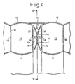
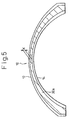
- Figure 4 is an enlarged section of a portion of the connection between the two pneumatic structures 10, indicated by "A" in Figure 3, and Figure 5 is an end view along line V-V in Figure 4.
- the abutments 28 are defined by end walls 30 which are made of the same material as the outer and inner walls 12 and 14.
- the end walls 30 can be made of a material more robust than that of the other walls to reinforce the abutments 28.
- the end walls 30 define spaces 32 which fluidly communicate with the air compartments 20 through the openings 18 which are provided in the outermost partition walls 16.
- the abutments 28 of the respective pneumatic structures 10 contact with each other by contacting surfaces 30a, shown by hatching in Figure 5.
- the pneumatic structures 10 In order to prevent water from entering the structure through the connection of the two pneumatic structures 10, the pneumatic structures 10 must be connected so that the contacting surface 30a includes a parameter K larger than 4 mm.
- the parameter K is a minimum dimension of an arbitrary line crossing the contacting surface 30a, and generally appears at the top of the structure 10.
- a parameter K larger than 4 mm can practically prevent the seepage.
- the authors further found that the relationship between the internal pressure P and the parameter K for preventing the seepage is as follows. P K ⁇ 0.2 ( Kg / cm 2 mm ) where
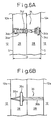
- Figure 6A shows an example of the bridle 34 which comprises a band 34a, a pair of eyelets 34b each of which is provided on the respective pneumatic structures 10 which are connected to each other, a bar 34c, which is provided at one end of the band 34a, for connecting the end of the band 34a to one of the eyelets 34b, and a buckle 34d.
- the bar 34c is inserted into one of the eyelets 34b to connect the end of the band 34a to the eyelet 34b.
- the other end of the band 34a is threaded into the other eyelet and secured to the band 34a by the buckle 34d.
- Each of the eyelets 34b is provided in a tab sewed into the seam "S" between the abutments 28 and the outer wall 12.
- This configuration enables adjustment of the parameter K by adjusting the distance "D" between the connected pneumatic structures 10, that is the length of the bridle 34. Further, the configuration allows the bridles 34 to be separated from the pneumatic structure 10 when it is not connected to another.
- Figure 6B shows another embodiment of the bridle 36 which comprises a first cord 36a in the form of a loop, a second cords 36b, and a bar attached to the end of the second cord 34b.
- the bar 36c is inserted into the loop of the first cord 36a to connect the first and second cords 34a and 34b as shown in Figure 6B.
- bridles 34 are shown provided on the exterior of the structures 10, the bridles 34 may be provided also on the interior of the structures 10.
- the two pneumatic structures 10 In use, at the installation of the connected form of the pneumatic structures 10, the two pneumatic structures 10 first connected to each other by the bridles 34 or 36, then air is supplied into the structures 10 by the air source 26 through the conduits 26a and the ports 24. After air supply, the conduit 26a is separated from the ports 25, and the ports 24 may by closed by plugs or closures (not shown). On the other hand, the air is discharged or drawn from each of the connected pneumatic structures 10 through the ports 24 to deflate the structures 10, then the bridles 34 or 36 are disconnected. After the deflation, the structures 10 are folded for storage.
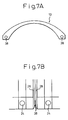
- the pneumatic structure 10 may include communication ports 38 in the abutments 28 as shown in Figures 7A and 7B.
- Figure 7B is a partially enlarged side view of the connection between the two pneumatic structures 10, in which the abutments 28 are illustrated separate from each other to show the communication ports 38.
- the communication ports 38 provided on the respective pneumatic structures 10 which are connected are coupled to each other by a fastener means, such as a zipper fastener, an inter-engaging fastener, or a hook and loop fastener.
- the communication ports 38 allows air to flow from one structure to the other so that air conduit for supplying air to the other structure can be eliminated.
- the communication ports 38 can be sealingly closed by a plug, a cap or a closure when the ports 38 are not used.
- An additional cover sheet 39 may be provided over the connection between the two pneumatic structures 10 for preventing water seepage, improving the appearance, or protecting the connection between the two structures 10.
- the additional cover sheet 39 may be attached to the structures 10 by a fastener means, such as a zipper fastener, an inter-engaging fastener, or a hook and loop fastener.
- the invention includes an embodiment, in which an additional cover sheet provided on the inner surface of the structure 10.
- Figure 8 shows additional cover sheets 39 and 39' which are provided outer and inner surface of the structure 10.
- a check valve 40 may be disposed in the openings 18 to control the air flow in the pneumatic structure 10.
- the valve 40 comprises a frame 40a in the form of a ring, a membrane 40b which is attached to an end face of the frame 40a by a screw fastener 40c, and a cross bar 40d for supporting the membrane 40b.
- the membrane 40b is flexible to allow one-way air flow as shown in Figure 9B.
- provision of the check valve 40 between the air compartment 20 and the space 32 of the abutments 28 increases the strength of the abutments 28, which allows the abutments 28 to press to each other, when the two pneumatic structures 10 are connected, so that the integrity of the pneumatic structure assembly is increased and the water seepage is eliminated.
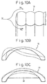
- Figure 10A is a partially sectional view of the front top portion of the pneumatic structure, in which a wind "W” flows into the structure.
- the wind “W” is divided into upper flow “W1” and lower flow “W2" by the front top portion of the structure as shown in Figure 10A.
- the separated flows “W1” and “W2” generate a fluid dynamic force which acts on and deforms the front top portion of the structure.
- Some conditions induce a self-oscillation in the structure to deform or collapse the entire structure as shown by dashed line in Figure 10B.
- the pneumatic structure 10 of the invention includes the screens 22 ( Figures 1 and 11A) for preventing this phenomena.
- the screen 22 may be made of woven, non-woven or knitted fabric. Further, the screen 22 can be made of a metallic or plastic plate or sheet.
- the screens 22 are provided to the upper portion of the opening of the structure 10 at the both ends thereof.
- the screens 22 reduce the lower flow "W2" to reduce the fluid dynamic force on the structure 10, and increase the strength of the structure.
- Figure 10C schematically shows the deformation of the pneumatic structure with a screen for reinforcement by a wind load.
- the screens 22 can be detachably or fixedly attached to the structure 10.
- a fastener means such as a zipper fastener, an inter-engaging fastener, a hook and loop fastener or an eyelet and cord assembly can be used.
- a reinforcement bar 42 may be provided at the lower end of the screen 22 as shown in Figure 11A.
- the screen 22 preferably has an effective opening height "h”, between the lower end of the screen and the ground, and a maximum height "H", that is "C” in Figure 2.
- the effective opening height "h” and the maximum height "H”, that is h/H is required to satisfy the following condition. h / H ⁇ 0.8
- the ratio h/H larger than 0.8 reduces the reinforcement effect and the obstruction effect for the lower flow "W2".
- the effective opening height "h” is preferably at least 2 m, for allowing the access to the structure 10, and the maximum height "H” is preferably at least 2.5 m, for ensure sufficient working space in the structure 10.
- FIG 11B shows a screen 22' according to another embodiment of the invention.
- the screen 22' substantially closes the opening of the structure 10 and includes an access opening 44.
- the effective height "h" is defined by the height of the access opening 44 as shown in Figure 11B.
- the pneumatic structure 10 may include at least a reinforcement in the form of an arch.
- Figure 12A is a side section of the structure 10 in which three reinforcements 46 provided along the inner surface of the structure 10
- Figure 12B is a side view of the structure 10 in which two reinforcements 48a are provided at the ends of the structure 10 and one reinforcement 48b is provided along the outer surface of the structure 10.
- the reinforcements 46, 48a and 48b may be made of a metal or plastic material or an air tube in the form of an arch or a semicircle.
- the reinforcement in the form of an air tube can be made of a woven fabric or knitted fabric made from a high-tenacity fiber, such as a polyester fiber, a polyamide fiber, an aramid fiber, a carbon fiber, a polyolefine fiber, or a polyacrylate fiber, and preferably a polyester fiber and an aramid fiber.
- a resin material such as polyurethane or vinyl chloride, or a rubber material such as acrylic rubber or fluoro rubber to provide impermeability.
- the air tube can be made of a sheet material which has a density of 100 - 600 g/m 2 . If the density is larger than 600 g/m 2 , the rigidity of the sheet is too high to impair the handling of the reinforcement. On the contrary, if the density is less than 100 g/m 2 , the strength of the sheet material is too low for the reinforcement.
- the reinforcements are attached to the structure by a fastener means, such as a zipper fastener, an inter-engaging fastener, a hook and loop fastener or an eyelet and cord assembly.
- a fastener means such as a zipper fastener, an inter-engaging fastener, a hook and loop fastener or an eyelet and cord assembly.
- the reinforcements can be integrally connected to the structure 10.
Landscapes
- Engineering & Computer Science (AREA)
- Architecture (AREA)
- Physics & Mathematics (AREA)
- Fluid Mechanics (AREA)
- Civil Engineering (AREA)
- Structural Engineering (AREA)
- Tents Or Canopies (AREA)
Description
- The invention relates to a pneumatic structure in the form of a barrel roof which is adapted to be provided over the entirety or a portion of a working or living space, such as a work site for maintenance or painting a watercraft, a construction site, a temporary site for an exhibition, or a stadium, and permits activity even under rain or snow. In particular, the invention relates to a pneumatic structure which is light and is capable of bearing a wind or snow load.
- Rain or snow often interrupts an outside work which decreases the efficiency of the work. However, there are cases in which the schedule cannot be delayed. Thus, in order to ensure a working or living space such as a work site for maintenance and painting a watercraft, a construction site, a temporary site for an exhibition, or a stadium, and to permit activity even under rain or snow (in the following description, "working or living space" is referred to "working space"), pneumatic structures in the form of a barrel roof have been developed. Such pneumatic structures include one for semi-permanent use and one for temporary use.
- Japanese Unexamined Patent Publication (Kokai) No. 9-144382, which was filed on June 4, 1997 by the applicant, describes a pneumatic structure for temporary use. The pneumatic structure includes outer and inner sheets or membranes connected by reinforcement sheets or membranes in the form of ribs, which define a plurality of air compartments into which compressed air is introduced to inflate the structure. The partition walls include openings which allow air to flow between the air compartments.
- The pneumatic structure of the prior art is capable of protecting a working space from rain, but heavy snow and gales, for example winds over 10 m/sec collapse the pneumatic structure. This problem is serious in case of large structure since the larger the structure, the larger the snow or wind load on the structure.
- In addition to the above problems, in order to provide a larger working space, a larger pneumatic structure is required. This increases the weight and the labor for transportation, installation, and deinstallation of the structure.
- Further, DE 1 961 523 A discloses a pneumatic structure according to the preamble of claim 1.
- The invention is directed to solve the problems of the prior art, and to provide a pneumatic structure improved to facilitate transportation, installation, and deinstallation even if the size of the structure is increased.
- The objective of the invention is also to provide a pneumatic structure improved to increase its strength against snow or wind loads.
- The invention provides a pneumatic structure in the form of a barrel roof which has openings at the opposite ends thereof. The pneumatic structure comprises outer and inner walls of a sheet or membrane material connected by a plurality of partition walls of a sheet or membrane material in the form of ribs provided therebetween to define a plurality of air compartments in the form of ribs between the outer and inner walls; the partition walls including a plurality of openings for fluid communication between adjacent air compartments.
- According to another feature of the invention, there is provided a pneumatic structure assembly in the form of a barrel roof which has openings at the opposite ends thereof. The pneumatic structure assembly comprises at least two pneumatic structure portions which are connected to each other at the ends of the respective structure portions. Each of the pneumatic structure comprises outer and inner walls of a sheet or membrane material connected by a plurality of partition walls in the form of ribs provided therebetween to define a plurality of air compartments in the form of ribs between the outer and inner walls; and an abutment, provided at an end of the structure portion, for contacting the abutment portion of the other pneumatic structure portion when the two pneumatic structure portions are connected to each other. The partition walls including a plurality of openings for fluid communication between adjacent air compartments.
- The pneumatic structure has specific dimensions defined as follows.


- a :
- the maximum opening width of the pneumatic structure;
- b :
- the total width of the pneumatic structure;
- c :
- the effective height (between ground and the maximum height of the inner wall); and
- d :
- the total height (between ground and the maximum height of the outer wall).
- These and other objects and advantages and further description will now be discussed in connection with the drawings in which:
- Figure 1 is a partially sectional perspective view of a pneumatic structure of the invention;
- Figure 2 is a front view of the pneumatic structure of Figure 1;
- Figure 3 is a side elevation of a pneumatic structure assembly of the invention;
- Figure 4 is an enlarged section of a portion indicated by "A" in Figure 3;
- Figure 5 is a section of the pneumatic structure assembly along line V - V in Figure 4;
- Figure 6A is an enlarged illustration of a bridle for connecting two pneumatic structures;
- Figure 6B is an enlarged illustration of another form of the bridle for connecting two pneumatic structures;
- Figure 7A is an end view of the pneumatic structure along V - V in Figure 4 in which communication ports are shown;
- Figure 7B is an partially enlarged side view of the pneumatic structure assembly for illustrating the connection between two communication ports;
- Figure 8 is an enlarged section similar to Figure 4 in which an additional cover sheet is shown;
- Figure 9A is a front view of a check valve;
- Figure 9B is a section of the check valve shown in Figure 9A;
- Figure 10A is partially sectional view of the front top portion of the pneumatic structure shown in Figure 1;
- Figure 10B is a schematic illustration of the deformation of the pneumatic structure by a wind load without a screen for reinforcement;
- Figure 10C is a schematic illustration of the deformation of the pneumatic structure by a wind load with a screen for reinforcement;
- Figure 11A is a front view of the pneumatic structure with the screen;
- Figure 11B shows another form of the screen;
- Figure 12A is a section of the pneumatic structure with three reinforcements extending along inner surface of the structure; and
- Figure 12B is a side view of the pneumatic structure with three reinforcements extending along outer surface of the structure.
- With reference to Figure 1, a
pneumatic structure 10 according to the invention comprises outer andinner walls partition walls 16 in the form of ribs to define a plurality of air compartments 20 (refer to Figure 4). Thepartition walls 16 includeopenings 18 to allow air flow between theair compartments 20. Thepneumatic structure 10 further includesscreens 22 andabutments 28 at the both ends of thestructure 10. - An
air source 26, including for example a fan, a blower or a compressor, supplies compressed air into the air compartments throughconduit 26a and at least one of a plurality ofports 24 to inflate thestructure 10. Providing theair source 26 with a heater (not shown) to supply hot air into the air compartments can melt snow accumulated on thepneumatic structure 10. - The outer, inner and partition walls comprise a sheet or membrane material of a woven fabric or knitted fabric from a high-tenacity fiber, such as a polyester fiber, a polyamide fiber, a aramid fiber, a carbon fiber, a polyolefine fiber, or a polyacrylate fiber, and preferably a polyester fiber, and a aramid fiber. Applied onto the fabric is a resin material such as polyurethane or vinyl chloride, or a rubber material such as acrylic rubber or fluoro rubber, to provide impermeability as described below.
- Further, the sheet or membrane material has a density which falls within a range of 30 - 200 g/m2, preferably 30 - 50 g/m2. In case of the density larger than 200 g/m2, the weight of the pneumatic structure increases and the relatively high rigidity of the sheet impair the handling of the structure. On the contrary, in case of density less than 30 g/m2, the strength of the sheet material is too low for the structure. In particular, for a relatively large sized pneumatic structure, the density of the sheet or membrane material is preferably selected within a range of 30 - 50 g/m2 to reduce the weight of the structure.
- Further, the air permeability of the sheet of membrane material is selected within a range of 0.1 cc/sec-m2 or less, preferably 0.02 cc/sec-m2 or less. In the most preferable case, an impermeable sheet material is used. Incidentally, the permeability is in compliance with "JIS L1096 Test Method For General Fabric", in which air flow per unit area and time through a sample fabric per is determined under differential pressure of 1.27 cm-Hg.
- The configuration of the
partition walls 16 is described below. - The
partition walls 16, in the form of ribs, extend parallel to each other between the outer andinner walls partition walls 16 are connected to the outer andinner walls pneumatic structure 10. As described above, thepartition walls 16 include a plurality ofopenings 18 which allow an air flow between the air compartments. Preferably, theopenings 18 have a total area which is 1/400 - 1/2 of that of thepartition walls 16. The upper limit of the area of theopenings 18 is determined by the strength ofpartition walls 16. On the other hand, the lower limit of the total area of theopenings 18 is determined by air flow between the air compartments, that is the time required by charge and discharge air into and from the structure. The preferable shape of theopenings 18 is a circle or an ellipse. - According to the feature of the invention, the
pneumatic structure 10 has specific dimensions as shown in Figure 2. In Figure 2, "a" is the maximum opening width, "b" is the total width, "c" is the effective height (between ground and the maximum height of the inner wall 14), "d" is the total height (between ground and the maximum height of the outer wall 14), "ru" is the radius of curvature of the outer wall at the top of the structure, and "rm" is also radius of curvature of the outer wall at the middle point along the outer wall between the top and the bottom of the structure. - According to the embodiment of the invention, the ratio of the total width "b" and the maximum opening width "a", that is b/a, preferably falls in a range of 1.20 - 1.35. The pneumatic structure which has the ratio b/a less than 1.20 tends to collapse due to snow or wind load. On the other hand, if the ratio b/a is more than 1.35, the effective area of the
pneumatic structure 10 usable for working is notable reduced relative to the total installed area, which results in an economic problem. - Further, according to the embodiment of the invention, the ratio of the total height "d" and the effective height "c", that is d/c, preferably falls in a range of 1.10 - 1.35. The pneumatic structure which has a ratio d/c of less than 1.10 tends to collapse due to a load such as a snow or wind load. On the other hand, a ratio d/c of more than 1.35 increases the amount of the material and thus the weight of the pneumatic structure to deteriorate the handling thereof. Further, the ratio d/c more than 1.35 increases the area of the side wall of the pneumatic structure, which receives wind pressure, so that the structure can easily collapse under the wind load.
- Further, according to the embodiment of the invention, the ratio of the maximum opening width "a" and the effective height, that is c/a, preferably falls in a range of 0.2 - 0.5. The ratio c/a less than 0.2 reduces the working space provided by the structure, and flattens the pneumatic structure to accumulate snow on the top of the structure and to make it difficult to remove snow on the top. The ratio more than 0.5 increases a wind load received by the structure, which makes the structure tend to collapse.
- Further, according to the invention, the ratio of the radius of curvature ru at the top of the structure and radius of curvature rm at the middle point, that is ru/rm, preferably falls in a range of 1.15 - 1.30. If the ratio ru/rm is smaller than 1.15, a wind load initially makes corrugations in the outer wall at the middle point. The larger the wind, the larger are the corrugations generated in the outer wall which will lead to the collapse of the structure. In order to prevent this, reinforcement is required for the structure. On the other hand, a ratio ru/rm of larger than 1.30 increases the front area of the structure which receives the wind to increase the wind load on the structure. Thus, increasing the ratio ru/rm to more than 1.30 is not effective to improve the strength of the structure.
- The
pneumatic structure 10 according to the embodiment of the invention has the configuration defined by the parameters as above, which configuration stabilizes the shape of the structure under a wind speed of 10 - 16 m/sec if the internal pressure is relatively low, for example 0.0037 Kg/cm2-g. Generally, the internal pressure of thepneumatic structure 10 is preferably selected within a range of 0.001 - 0.05 Kg/cm2-g. An internal pressure less than 0.001 Kg/cm2-g cannot maintain the structure under a snow or wind load. On the other hand, an internal pressure higher than 0.05 Kg/cm2-g entails increase of the strength of the outer, inner andpartition walls structure 10 and the deteriorate of handling of thestructure 10. Furthermore, in order to increase the internal pressure above 0.05 Kg/ cm2-g, a large fan, a blower or a compressor as theair source 26 is required to increase the cost therefor. - Although the
pneumatic structure 10 is shown as a single body in Figures 1 and 2, the invention includes an embodiment in which a plurality ofpneumatic structures 10 are connected to each other. With reference to Figures 3 and 4, the second embodiment of the invention will be described below. - Figure 3 shows a pneumatic structure assembly which includes two
pneumatic structures 10, as pneumatic structure portions, which are connected to each other by a plurality ofbridles 34. Theabutments 28 of the respective structure contact each other when thepneumatic structures 10 are connected. - This configuration provides an increased working area without deteriorating the handling of the structure since the size of each of the
structure 10 is not increased. - Figure 4 is an enlarged section of a portion of the connection between the two
pneumatic structures 10, indicated by "A" in Figure 3, and Figure 5 is an end view along line V-V in Figure 4. - The
abutments 28 are defined byend walls 30 which are made of the same material as the outer andinner walls end walls 30 can be made of a material more robust than that of the other walls to reinforce theabutments 28. Theend walls 30 definespaces 32 which fluidly communicate with the air compartments 20 through theopenings 18 which are provided in theoutermost partition walls 16. Theabutments 28 of the respectivepneumatic structures 10 contact with each other by contactingsurfaces 30a, shown by hatching in Figure 5. - In order to prevent water from entering the structure through the connection of the two
pneumatic structures 10, thepneumatic structures 10 must be connected so that the contactingsurface 30a includes a parameter K larger than 4 mm. The parameter K is a minimum dimension of an arbitrary line crossing the contactingsurface 30a, and generally appears at the top of thestructure 10. The larger the parameter K, the higher is the capability of preventing the seepage. However, the authors found that a parameter K larger than 4 mm can practically prevent the seepage. The authors further found that the relationship between the internal pressure P and the parameter K for preventing the seepage is as follows.
where - P :
- internal pressure (Kg/ cm2-g)
- K :
- minimum dimension of the contacting surface (mm)
- Figure 6A shows an example of the
bridle 34 which comprises a band 34a, a pair ofeyelets 34b each of which is provided on the respectivepneumatic structures 10 which are connected to each other, a bar 34c, which is provided at one end of the band 34a, for connecting the end of the band 34a to one of theeyelets 34b, and abuckle 34d. The bar 34c is inserted into one of theeyelets 34b to connect the end of the band 34a to theeyelet 34b. The other end of the band 34a is threaded into the other eyelet and secured to the band 34a by thebuckle 34d. Each of theeyelets 34b is provided in a tab sewed into the seam "S" between theabutments 28 and theouter wall 12. This configuration enables adjustment of the parameter K by adjusting the distance "D" between the connectedpneumatic structures 10, that is the length of thebridle 34. Further, the configuration allows thebridles 34 to be separated from thepneumatic structure 10 when it is not connected to another. - Figure 6B shows another embodiment of the
bridle 36 which comprises afirst cord 36a in the form of a loop, asecond cords 36b, and a bar attached to the end of thesecond cord 34b. Thebar 36c is inserted into the loop of thefirst cord 36a to connect the first andsecond cords 34a and 34b as shown in Figure 6B. - In Figures 3 and 4, although the
bridles 34 are shown provided on the exterior of thestructures 10, thebridles 34 may be provided also on the interior of thestructures 10. - In use, at the installation of the connected form of the
pneumatic structures 10, the twopneumatic structures 10 first connected to each other by thebridles structures 10 by theair source 26 through theconduits 26a and theports 24. After air supply, theconduit 26a is separated from the ports 25, and theports 24 may by closed by plugs or closures (not shown). On the other hand, the air is discharged or drawn from each of the connectedpneumatic structures 10 through theports 24 to deflate thestructures 10, then thebridles structures 10 are folded for storage. - The
pneumatic structure 10 may includecommunication ports 38 in theabutments 28 as shown in Figures 7A and 7B. Figure 7B is a partially enlarged side view of the connection between the twopneumatic structures 10, in which theabutments 28 are illustrated separate from each other to show thecommunication ports 38. Thecommunication ports 38 provided on the respectivepneumatic structures 10 which are connected are coupled to each other by a fastener means, such as a zipper fastener, an inter-engaging fastener, or a hook and loop fastener. Thecommunication ports 38 allows air to flow from one structure to the other so that air conduit for supplying air to the other structure can be eliminated. Thecommunication ports 38 can be sealingly closed by a plug, a cap or a closure when theports 38 are not used. - An
additional cover sheet 39 may be provided over the connection between the twopneumatic structures 10 for preventing water seepage, improving the appearance, or protecting the connection between the twostructures 10. Theadditional cover sheet 39 may be attached to thestructures 10 by a fastener means, such as a zipper fastener, an inter-engaging fastener, or a hook and loop fastener. The invention includes an embodiment, in which an additional cover sheet provided on the inner surface of thestructure 10. Figure 8 showsadditional cover sheets 39 and 39' which are provided outer and inner surface of thestructure 10. - According to another feature of the invention, a
check valve 40 may be disposed in theopenings 18 to control the air flow in thepneumatic structure 10. Thevalve 40 comprises aframe 40a in the form of a ring, a membrane 40b which is attached to an end face of theframe 40a by ascrew fastener 40c, and across bar 40d for supporting the membrane 40b. The membrane 40b is flexible to allow one-way air flow as shown in Figure 9B. Providing thecheck valves 40 in some of the appropriately selectedopenings 18 enables control of the air flow in thepneumatic structure 10 so that the resistance to deformation under load is increased. In particular, provision of thecheck valve 40 between theair compartment 20 and thespace 32 of theabutments 28 increases the strength of theabutments 28, which allows theabutments 28 to press to each other, when the twopneumatic structures 10 are connected, so that the integrity of the pneumatic structure assembly is increased and the water seepage is eliminated. - Another feature of the invention will be described below with reference to Figures 10A, 10B and 10C.
- Figure 10A is a partially sectional view of the front top portion of the pneumatic structure, in which a wind "W" flows into the structure. When the wind "W" meets the
structure 10, the wind "W" is divided into upper flow "W1" and lower flow "W2" by the front top portion of the structure as shown in Figure 10A. The separated flows "W1" and "W2" generate a fluid dynamic force which acts on and deforms the front top portion of the structure. Some conditions induce a self-oscillation in the structure to deform or collapse the entire structure as shown by dashed line in Figure 10B. - The
pneumatic structure 10 of the invention includes the screens 22 (Figures 1 and 11A) for preventing this phenomena. Thescreen 22 may be made of woven, non-woven or knitted fabric. Further, thescreen 22 can be made of a metallic or plastic plate or sheet. - The
screens 22 are provided to the upper portion of the opening of thestructure 10 at the both ends thereof. Thescreens 22 reduce the lower flow "W2" to reduce the fluid dynamic force on thestructure 10, and increase the strength of the structure. Figure 10C schematically shows the deformation of the pneumatic structure with a screen for reinforcement by a wind load. Thescreens 22 can be detachably or fixedly attached to thestructure 10. In case that thescreens 22 are detachably attached to thestructure 10, a fastener means, such as a zipper fastener, an inter-engaging fastener, a hook and loop fastener or an eyelet and cord assembly can be used. Detaching thescreens 22 increases the size, in particular the height of the openings of thestructure 10, which allows a relatively high machine or a falsework to enter thestructure 10, and provides lighting. Areinforcement bar 42 may be provided at the lower end of thescreen 22 as shown in Figure 11A. - With reference to Figure 11A, the
screen 22 preferably has an effective opening height "h", between the lower end of the screen and the ground, and a maximum height "H", that is "C" in Figure 2. According to the embodiment of the invention, the effective opening height "h" and the maximum height "H", that is h/H is required to satisfy the following condition.
- The ratio h/H larger than 0.8 reduces the reinforcement effect and the obstruction effect for the lower flow "W2". Further, the effective opening height "h" is preferably at least 2 m, for allowing the access to the
structure 10, and the maximum height "H" is preferably at least 2.5 m, for ensure sufficient working space in thestructure 10. - Figure 11B shows a screen 22' according to another embodiment of the invention. The screen 22' substantially closes the opening of the
structure 10 and includes anaccess opening 44. In this case, the effective height "h" is defined by the height of the access opening 44 as shown in Figure 11B. - The
pneumatic structure 10 may include at least a reinforcement in the form of an arch. Figure 12A is a side section of thestructure 10 in which threereinforcements 46 provided along the inner surface of thestructure 10, and Figure 12B is a side view of thestructure 10 in which tworeinforcements 48a are provided at the ends of thestructure 10 and onereinforcement 48b is provided along the outer surface of thestructure 10. Thereinforcements - The air tube can be made of a sheet material which has a density of 100 - 600 g/m2. If the density is larger than 600 g/m2, the rigidity of the sheet is too high to impair the handling of the reinforcement. On the contrary, if the density is less than 100 g/m2, the strength of the sheet material is too low for the reinforcement.
- The reinforcements are attached to the structure by a fastener means, such as a zipper fastener, an inter-engaging fastener, a hook and loop fastener or an eyelet and cord assembly. In case of an air tube, the reinforcements can be integrally connected to the
structure 10. - It will also be understood by those skilled in the art that the forgoing description is a preferred embodiment of the disclosed device and that various changes and modifications may be made without departing from the scope of the invention as defined in the claims.
Claims (12)
- A pneumatic structure (10) in the form of a barrel roof which has openings at the opposite ends thereof, comprising:outer (12) and inner (14) walls of a sheet or membrane material connected by a plurality of partition walls (16) of a sheet or membrane material in the form of ribs provided therebetween to define a plurality of air compartments (20) in the form of ribs between the outer (12) and inner (14) walls; the partition walls (16) including a plurality of openings (18) for fluid communication between adjacent air compartments;
characterized in that the pneumatic structure (10) has specific dimensions defined as follows:


wherea: the maximum opening width of the pneumatic structure (10);b: the total width of the pneumatic structure (10);c: the effective height between ground and the maximum height of the inner wall (14); andd: the total height between ground and the maximum height of the outer wall (12). - A pneumatic structure according to claim 1 wherein the pneumatic structure (10) further has specific dimensions defined as follows.

whereru: radius of curvature of the outer wall (12) at the top of the structure; andrm: radius of curvature of the outer wall (12) at the middle point along the outer wall between the top and the bottom of the structure. - A pneumatic structure according to claim 2 further comprising screens (22), provided at the ends of the structure, for preventing the deformation of the structure at the ends thereof.
- A pneumatic structure according to claim 3 wherein the screens (22) have specific dimensions defined as follows.


whereh: the effective opening height between the lower end and the ground where the structure is installed; andH: the total height between ground and the maximum height of the outer wall (12). - A pneumatic structure according to claim 4 wherein the screens (22) are detachably attached to the ends of the structure.
- A pneumatic structure according to claim 5 wherein the screens (22) comprise a knitted material.
- A pneumatic structure according to claim 4 wherein the screens (22) include reinforcement a bar (42) extending along the lower end of the screen.
- A pneumatic structure according to claim 5 wherein the screens (22) are integrally connected to the inner wall.
- A pneumatic structure according to claim 1, wherein the material defining the outer (12) and inner (14) walls has a density which falls within a range of 30 - 200 g/m2, and an air permeability within a range of 0.1 cc/sec-m2.
- A pneumatic structure according to claim 1 further comprising at least a check valve (40), provided in the opening (18) in the partition walls (16), for controlling the air flow in the pneumatic structure.
- A pneumatic structure according to claim 1 further comprising at least a reinforcement member (46, 48a, 48b) in the form of an arch, the reinforcement comprising an air tube of a sheet material which has a density of 100 - 600 g/m2.
- A pneumatic structure assembly in the form of a barrel roof which has openings at the opposite ends thereof, comprising:at least two pneumatic structures according to any of claims 1 to 11 which are connected to each other at the ends of the respective structure portions;each of the pneumatic structure comprising an abutment, provided at an end of the structure portion, for contacting the abutment portion of the other pneumatic structure portion when the two pneumatic structure portions are connected to each other.
Applications Claiming Priority (2)
| Application Number | Priority Date | Filing Date | Title |
|---|---|---|---|
| JP9185998 | 1998-04-03 | ||
| JP09185998A JP3574743B2 (en) | 1998-04-03 | 1998-04-03 | Air film structure |
Publications (3)
| Publication Number | Publication Date |
|---|---|
| EP0947645A2 EP0947645A2 (en) | 1999-10-06 |
| EP0947645A3 EP0947645A3 (en) | 2000-06-14 |
| EP0947645B1 true EP0947645B1 (en) | 2006-03-08 |
Family
ID=14038292
Family Applications (1)
| Application Number | Title | Priority Date | Filing Date |
|---|---|---|---|
| EP98122580A Expired - Lifetime EP0947645B1 (en) | 1998-04-03 | 1998-12-03 | A pneumatic structure |
Country Status (9)
| Country | Link |
|---|---|
| US (1) | US6282843B1 (en) |
| EP (1) | EP0947645B1 (en) |
| JP (1) | JP3574743B2 (en) |
| KR (1) | KR100313623B1 (en) |
| CN (1) | CN1131920C (en) |
| AU (1) | AU745968B2 (en) |
| CA (1) | CA2252956A1 (en) |
| DE (1) | DE69833718T2 (en) |
| TW (1) | TW430711B (en) |
Families Citing this family (30)
| Publication number | Priority date | Publication date | Assignee | Title |
|---|---|---|---|---|
| ATE373155T1 (en) * | 2001-07-05 | 2007-09-15 | Eads Deutschland Gmbh | PNEUMATIC WALL CONSTRUCTION |
| JP3763780B2 (en) | 2001-12-20 | 2006-04-05 | Ykk Ap株式会社 | Air tent |
| ATE383481T1 (en) * | 2003-08-27 | 2008-01-15 | Prospective Concepts Ag | FLOATING SUPPORT STRUCTURE WITH STATIC BUOYANCY |
| CN100449098C (en) * | 2003-11-04 | 2009-01-07 | 未来概念公司 | Pneumatic two-dimensional structure |
| US20050198741A1 (en) * | 2004-03-02 | 2005-09-15 | Epstein Adam S. | Inflatable support members and structures including the same |
| WO2007016328A1 (en) | 2005-07-29 | 2007-02-08 | The Elumenati, Llc | Dual pressure inflatable structure and method |
| CH704442B1 (en) * | 2005-12-23 | 2012-08-15 | Prospective Concepts Ag | Pneumatic component. |
| US8161686B2 (en) * | 2005-12-23 | 2012-04-24 | Prospective Concepts Ag | Pneumatic structural element, and roof produced therefrom |
| US8572911B1 (en) * | 2006-02-13 | 2013-11-05 | University Of Akron Research Foundation | Inflatable structure with internal support |
| US20080110538A1 (en) * | 2006-11-09 | 2008-05-15 | Ioannis Varonos | Generic inflatable protective cover and methods for manufacturing same |
| KR100974027B1 (en) * | 2008-03-26 | 2010-08-04 | (주)에어박스 | A tent that frame consists by air |
| US8991104B2 (en) * | 2008-09-05 | 2015-03-31 | Dynamic Shelters Inc. | Method and apparatus for distributing a load about an air beam |
| WO2012065042A1 (en) | 2010-11-11 | 2012-05-18 | Paha Designs | Quick deploy fire shelter |
| CN102100594B (en) * | 2011-04-02 | 2013-04-10 | 中国人民解放军军事医学科学院卫生装备研究所 | Negative pressure isolated air charging stretcher for infected patient |
| US9499970B2 (en) * | 2011-05-17 | 2016-11-22 | International Shelter Solutions LLC | Method and apparatus for building a structure |
| US8243366B1 (en) * | 2011-06-27 | 2012-08-14 | Deutsch Inc. | Projection screen with wind shield |
| US9985476B2 (en) * | 2012-07-02 | 2018-05-29 | Fuji Machine Mfg. Co., Ltd. | Electrostatic coupling type contactless electric power supply device |
| FR2995335B1 (en) * | 2012-09-12 | 2015-11-13 | Gaetan Guibert | INFLATABLE FRAME |
| JP2015001094A (en) * | 2013-06-14 | 2015-01-05 | 株式会社スカイブルー | Membrane structure |
| CN104110156B (en) * | 2014-06-30 | 2016-01-27 | 铱格斯曼航空科技集团有限公司 | A kind of gas rib being applicable to large-scale air filling type ship/hangar |
| US10400462B2 (en) * | 2016-05-04 | 2019-09-03 | Monolithic Constructors, Inc. | Transverse span airform structure |
| CN107288220A (en) * | 2017-08-03 | 2017-10-24 | 北京元恒大通科技有限公司 | Inflatable Building block |
| US10995513B2 (en) * | 2017-10-12 | 2021-05-04 | Air Structures American Technologies, Inc. | Air supported structures with frozen precipitation accumulation prevention |
| WO2019136235A1 (en) * | 2018-01-05 | 2019-07-11 | Rowan University | Inflatable impact shield system |
| CN210598386U (en) * | 2019-01-15 | 2020-05-22 | Jg和Am史密斯投资有限公司 | Portable sunshade assembly |
| KR102089987B1 (en) * | 2019-08-05 | 2020-03-18 | 주식회사 제이치글로벌 | Air dome comprising visible light active photocatalyst |
| US11313146B2 (en) * | 2019-11-18 | 2022-04-26 | Ray D. Robertson | Method and product to prevent flooding of a motor vehicle in high water |
| KR102282317B1 (en) * | 2020-11-10 | 2021-07-27 | (주)지티씨코퍼레이션 | An equipment for safety on constructing a tunnel |
| KR102615514B1 (en) * | 2022-06-02 | 2023-12-19 | 유광산 | Tunnel safety apparatus and tunnel constuction method using same |
| CN115075651B (en) * | 2022-07-25 | 2022-10-25 | 河南新飞电器集团有限公司 | Temperature automatic control intelligent air film shelter venue based on 5G technology |
Family Cites Families (6)
| Publication number | Priority date | Publication date | Assignee | Title |
|---|---|---|---|---|
| FR1602054A (en) * | 1968-12-09 | 1970-10-05 | ||
| GB2044871A (en) * | 1979-02-10 | 1980-10-22 | Beaufort Air Sea Equipment Ltd | A method of jointing inflatable tubes |
| GB2135354A (en) * | 1983-01-18 | 1984-08-30 | Boo Kiang Chew | Tents |
| JPS60242269A (en) | 1984-05-16 | 1985-12-02 | 小川テント株式会社 | Variable type air structure construction |
| JP3099455B2 (en) | 1990-10-08 | 2000-10-16 | 住友化学工業株式会社 | Aromatic polyester and method for producing the same |
| JP3282016B2 (en) | 1995-11-29 | 2002-05-13 | 三菱重工業株式会社 | Rain dust guard air film roof |
-
1998
- 1998-04-03 JP JP09185998A patent/JP3574743B2/en not_active Expired - Lifetime
- 1998-12-02 AU AU95184/98A patent/AU745968B2/en not_active Ceased
- 1998-12-02 TW TW087119966A patent/TW430711B/en not_active IP Right Cessation
- 1998-12-02 CA CA002252956A patent/CA2252956A1/en not_active Abandoned
- 1998-12-03 KR KR1019980052854A patent/KR100313623B1/en not_active IP Right Cessation
- 1998-12-03 CN CN98125256A patent/CN1131920C/en not_active Expired - Fee Related
- 1998-12-03 EP EP98122580A patent/EP0947645B1/en not_active Expired - Lifetime
- 1998-12-03 DE DE69833718T patent/DE69833718T2/en not_active Expired - Lifetime
-
2000
- 2000-05-12 US US09/570,058 patent/US6282843B1/en not_active Expired - Fee Related
Also Published As
| Publication number | Publication date |
|---|---|
| AU745968B2 (en) | 2002-04-11 |
| US6282843B1 (en) | 2001-09-04 |
| EP0947645A2 (en) | 1999-10-06 |
| DE69833718D1 (en) | 2006-05-04 |
| JPH11287056A (en) | 1999-10-19 |
| AU9518498A (en) | 1999-10-14 |
| CA2252956A1 (en) | 1999-10-03 |
| KR19990081795A (en) | 1999-11-15 |
| EP0947645A3 (en) | 2000-06-14 |
| KR100313623B1 (en) | 2001-12-20 |
| CN1231373A (en) | 1999-10-13 |
| DE69833718T2 (en) | 2006-10-05 |
| TW430711B (en) | 2001-04-21 |
| CN1131920C (en) | 2003-12-24 |
| JP3574743B2 (en) | 2004-10-06 |
Similar Documents
| Publication | Publication Date | Title |
|---|---|---|
| EP0947645B1 (en) | A pneumatic structure | |
| US5570544A (en) | Inflatable structure | |
| US6179367B1 (en) | Inflatable tent for sport utility vehicle | |
| US5924144A (en) | Inflatable swimming pool and supporting shell | |
| US2854014A (en) | Inflatable shelter | |
| EP0958159B1 (en) | A carrier for vehicle roofs | |
| US5677023A (en) | Reinforced fabric inflatable tube | |
| US6751892B2 (en) | Minefield shoe and method for manufacture thereof | |
| CN109292485A (en) | For sealing or covering the weather barrier device of the vehicle at loading platform | |
| US4101062A (en) | Inflatable cartop carrier and shelter structure | |
| US20040040082A1 (en) | Self-rising swimming pool construction | |
| US4067544A (en) | Pneumatic flat pads | |
| US20060103165A1 (en) | Protective vehicle cover and method of use | |
| SK7464Y1 (en) | Inflatable tent | |
| CN108060826B (en) | High-pressure tent | |
| US5678358A (en) | Soldier fighting cover | |
| CN108060827B (en) | Gas column supporting system for high-pressure tent | |
| US20030070237A1 (en) | Pneumatic mattress | |
| CN115917099A (en) | Tent comprising a bed base | |
| US20220312706A1 (en) | Plant pollination control structures | |
| GB2275893A (en) | Oil containment boom. | |
| JP2000073624A (en) | Air-inflated membrane structural body | |
| WO2005032886A2 (en) | Protective vehicle cover and method of use | |
| IT9022397A1 (en) | SELF-SUPPORTING PNEUMATIC COVER | |
| WO2016039790A1 (en) | Weather barrier apparatuses for sealing or sheltering vehicles at loading docks |
Legal Events
| Date | Code | Title | Description |
|---|---|---|---|
| PUAI | Public reference made under article 153(3) epc to a published international application that has entered the european phase |
Free format text: ORIGINAL CODE: 0009012 |
|
| AK | Designated contracting states |
Kind code of ref document: A2 Designated state(s): DE FR GB IT |
|
| AX | Request for extension of the european patent |
Free format text: AL;LT;LV;MK;RO;SI |
|
| PUAL | Search report despatched |
Free format text: ORIGINAL CODE: 0009013 |
|
| AK | Designated contracting states |
Kind code of ref document: A3 Designated state(s): AT BE CH CY DE DK ES FI FR GB GR IE IT LI LU MC NL PT SE |
|
| AX | Request for extension of the european patent |
Free format text: AL;LT;LV;MK;RO;SI |
|
| 17P | Request for examination filed |
Effective date: 20001031 |
|
| AKX | Designation fees paid |
Free format text: DE FR GB IT |
|
| 17Q | First examination report despatched |
Effective date: 20030818 |
|
| GRAP | Despatch of communication of intention to grant a patent |
Free format text: ORIGINAL CODE: EPIDOSNIGR1 |
|
| GRAS | Grant fee paid |
Free format text: ORIGINAL CODE: EPIDOSNIGR3 |
|
| GRAA | (expected) grant |
Free format text: ORIGINAL CODE: 0009210 |
|
| AK | Designated contracting states |
Kind code of ref document: B1 Designated state(s): DE FR GB IT |
|
| REG | Reference to a national code |
Ref country code: GB Ref legal event code: FG4D |
|
| REF | Corresponds to: |
Ref document number: 69833718 Country of ref document: DE Date of ref document: 20060504 Kind code of ref document: P |
|
| ET | Fr: translation filed | ||
| PLBE | No opposition filed within time limit |
Free format text: ORIGINAL CODE: 0009261 |
|
| STAA | Information on the status of an ep patent application or granted ep patent |
Free format text: STATUS: NO OPPOSITION FILED WITHIN TIME LIMIT |
|
| 26N | No opposition filed |
Effective date: 20061211 |
|
| PGFP | Annual fee paid to national office [announced via postgrant information from national office to epo] |
Ref country code: IT Payment date: 20091027 Year of fee payment: 12 Ref country code: GB Payment date: 20091221 Year of fee payment: 12 Ref country code: FR Payment date: 20091203 Year of fee payment: 12 |
|
| PGFP | Annual fee paid to national office [announced via postgrant information from national office to epo] |
Ref country code: DE Payment date: 20091123 Year of fee payment: 12 |
|
| GBPC | Gb: european patent ceased through non-payment of renewal fee |
Effective date: 20101203 |
|
| REG | Reference to a national code |
Ref country code: FR Ref legal event code: ST Effective date: 20110831 |
|
| PG25 | Lapsed in a contracting state [announced via postgrant information from national office to epo] |
Ref country code: FR Free format text: LAPSE BECAUSE OF NON-PAYMENT OF DUE FEES Effective date: 20110103 |
|
| REG | Reference to a national code |
Ref country code: DE Ref legal event code: R119 Ref document number: 69833718 Country of ref document: DE Effective date: 20110701 |
|
| PG25 | Lapsed in a contracting state [announced via postgrant information from national office to epo] |
Ref country code: GB Free format text: LAPSE BECAUSE OF NON-PAYMENT OF DUE FEES Effective date: 20101203 Ref country code: DE Free format text: LAPSE BECAUSE OF NON-PAYMENT OF DUE FEES Effective date: 20110701 |
|
| PG25 | Lapsed in a contracting state [announced via postgrant information from national office to epo] |
Ref country code: IT Free format text: LAPSE BECAUSE OF NON-PAYMENT OF DUE FEES Effective date: 20101203 |