EP0947423B1 - Autonomous helicopter blade end lighting device - Google Patents
Autonomous helicopter blade end lighting device Download PDFInfo
- Publication number
- EP0947423B1 EP0947423B1 EP99301653A EP99301653A EP0947423B1 EP 0947423 B1 EP0947423 B1 EP 0947423B1 EP 99301653 A EP99301653 A EP 99301653A EP 99301653 A EP99301653 A EP 99301653A EP 0947423 B1 EP0947423 B1 EP 0947423B1
- Authority
- EP
- European Patent Office
- Prior art keywords
- light source
- helicopter
- rotor blade
- helicopter rotor
- battery
- Prior art date
- Legal status (The legal status is an assumption and is not a legal conclusion. Google has not performed a legal analysis and makes no representation as to the accuracy of the status listed.)
- Expired - Lifetime
Links
- 239000003792 electrolyte Substances 0.000 claims description 15
- WHXSMMKQMYFTQS-UHFFFAOYSA-N Lithium Chemical compound [Li] WHXSMMKQMYFTQS-UHFFFAOYSA-N 0.000 claims description 7
- 229910052744 lithium Inorganic materials 0.000 claims description 7
- 230000004297 night vision Effects 0.000 claims description 5
- 238000007789 sealing Methods 0.000 claims description 4
- 239000000126 substance Substances 0.000 claims description 4
- SOZVEOGRIFZGRO-UHFFFAOYSA-N [Li].ClS(Cl)=O Chemical compound [Li].ClS(Cl)=O SOZVEOGRIFZGRO-UHFFFAOYSA-N 0.000 claims description 3
- 238000012423 maintenance Methods 0.000 claims description 3
- 239000004065 semiconductor Substances 0.000 claims description 3
- 238000000034 method Methods 0.000 claims description 2
- 238000005303 weighing Methods 0.000 claims 1
- 230000015572 biosynthetic process Effects 0.000 description 4
- 230000000694 effects Effects 0.000 description 3
- 238000010586 diagram Methods 0.000 description 2
- 238000012986 modification Methods 0.000 description 2
- 230000004048 modification Effects 0.000 description 2
- 230000005855 radiation Effects 0.000 description 2
- 230000003595 spectral effect Effects 0.000 description 2
- 241000260460 Buteogallus Species 0.000 description 1
- JFLRKDZMHNBDQS-UCQUSYKYSA-N CC[C@H]1CCC[C@@H]([C@H](C(=O)C2=C[C@H]3[C@@H]4C[C@@H](C[C@H]4C(=C[C@H]3[C@@H]2CC(=O)O1)C)O[C@H]5[C@@H]([C@@H]([C@H]([C@@H](O5)C)OC)OC)OC)C)O[C@H]6CC[C@@H]([C@H](O6)C)N(C)C.CC[C@H]1CCC[C@@H]([C@H](C(=O)C2=C[C@H]3[C@@H]4C[C@@H](C[C@H]4C=C[C@H]3C2CC(=O)O1)O[C@H]5[C@@H]([C@@H]([C@H]([C@@H](O5)C)OC)OC)OC)C)O[C@H]6CC[C@@H]([C@H](O6)C)N(C)C Chemical compound CC[C@H]1CCC[C@@H]([C@H](C(=O)C2=C[C@H]3[C@@H]4C[C@@H](C[C@H]4C(=C[C@H]3[C@@H]2CC(=O)O1)C)O[C@H]5[C@@H]([C@@H]([C@H]([C@@H](O5)C)OC)OC)OC)C)O[C@H]6CC[C@@H]([C@H](O6)C)N(C)C.CC[C@H]1CCC[C@@H]([C@H](C(=O)C2=C[C@H]3[C@@H]4C[C@@H](C[C@H]4C=C[C@H]3C2CC(=O)O1)O[C@H]5[C@@H]([C@@H]([C@H]([C@@H](O5)C)OC)OC)OC)C)O[C@H]6CC[C@@H]([C@H](O6)C)N(C)C JFLRKDZMHNBDQS-UCQUSYKYSA-N 0.000 description 1
- 235000014676 Phragmites communis Nutrition 0.000 description 1
- 241000270295 Serpentes Species 0.000 description 1
- 239000000853 adhesive Substances 0.000 description 1
- 230000001070 adhesive effect Effects 0.000 description 1
- 239000003990 capacitor Substances 0.000 description 1
- 239000002131 composite material Substances 0.000 description 1
- 238000010276 construction Methods 0.000 description 1
- 230000007123 defense Effects 0.000 description 1
- 238000005516 engineering process Methods 0.000 description 1
- 238000004519 manufacturing process Methods 0.000 description 1
- 230000002459 sustained effect Effects 0.000 description 1
Images
Classifications
-
- B—PERFORMING OPERATIONS; TRANSPORTING
- B64—AIRCRAFT; AVIATION; COSMONAUTICS
- B64D—EQUIPMENT FOR FITTING IN OR TO AIRCRAFT; FLIGHT SUITS; PARACHUTES; ARRANGEMENT OR MOUNTING OF POWER PLANTS OR PROPULSION TRANSMISSIONS IN AIRCRAFT
- B64D47/00—Equipment not otherwise provided for
- B64D47/02—Arrangements or adaptations of signal or lighting devices
- B64D47/06—Arrangements or adaptations of signal or lighting devices for indicating aircraft presence
-
- H—ELECTRICITY
- H05—ELECTRIC TECHNIQUES NOT OTHERWISE PROVIDED FOR
- H05B—ELECTRIC HEATING; ELECTRIC LIGHT SOURCES NOT OTHERWISE PROVIDED FOR; CIRCUIT ARRANGEMENTS FOR ELECTRIC LIGHT SOURCES, IN GENERAL
- H05B45/00—Circuit arrangements for operating light-emitting diodes [LED]
- H05B45/30—Driver circuits
-
- H—ELECTRICITY
- H05—ELECTRIC TECHNIQUES NOT OTHERWISE PROVIDED FOR
- H05B—ELECTRIC HEATING; ELECTRIC LIGHT SOURCES NOT OTHERWISE PROVIDED FOR; CIRCUIT ARRANGEMENTS FOR ELECTRIC LIGHT SOURCES, IN GENERAL
- H05B47/00—Circuit arrangements for operating light sources in general, i.e. where the type of light source is not relevant
- H05B47/10—Controlling the light source
- H05B47/105—Controlling the light source in response to determined parameters
-
- H—ELECTRICITY
- H05—ELECTRIC TECHNIQUES NOT OTHERWISE PROVIDED FOR
- H05B—ELECTRIC HEATING; ELECTRIC LIGHT SOURCES NOT OTHERWISE PROVIDED FOR; CIRCUIT ARRANGEMENTS FOR ELECTRIC LIGHT SOURCES, IN GENERAL
- H05B47/00—Circuit arrangements for operating light sources in general, i.e. where the type of light source is not relevant
- H05B47/10—Controlling the light source
- H05B47/105—Controlling the light source in response to determined parameters
- H05B47/11—Controlling the light source in response to determined parameters by determining the brightness or colour temperature of ambient light
-
- B—PERFORMING OPERATIONS; TRANSPORTING
- B64—AIRCRAFT; AVIATION; COSMONAUTICS
- B64D—EQUIPMENT FOR FITTING IN OR TO AIRCRAFT; FLIGHT SUITS; PARACHUTES; ARRANGEMENT OR MOUNTING OF POWER PLANTS OR PROPULSION TRANSMISSIONS IN AIRCRAFT
- B64D2203/00—Aircraft or airfield lights using LEDs
-
- Y—GENERAL TAGGING OF NEW TECHNOLOGICAL DEVELOPMENTS; GENERAL TAGGING OF CROSS-SECTIONAL TECHNOLOGIES SPANNING OVER SEVERAL SECTIONS OF THE IPC; TECHNICAL SUBJECTS COVERED BY FORMER USPC CROSS-REFERENCE ART COLLECTIONS [XRACs] AND DIGESTS
- Y02—TECHNOLOGIES OR APPLICATIONS FOR MITIGATION OR ADAPTATION AGAINST CLIMATE CHANGE
- Y02B—CLIMATE CHANGE MITIGATION TECHNOLOGIES RELATED TO BUILDINGS, e.g. HOUSING, HOUSE APPLIANCES OR RELATED END-USER APPLICATIONS
- Y02B20/00—Energy efficient lighting technologies, e.g. halogen lamps or gas discharge lamps
- Y02B20/40—Control techniques providing energy savings, e.g. smart controller or presence detection
Definitions
- the present invention relates to a lighting device and, more particularly, to an autonomous lighting device for helicopter blade end (tip).
- a helicopter is an aircraft that is lifted and sustained in the air horizontally by rotating wings or blades turning on vertical axes through power supplied by an engine.
- Helicopters are used for civil, military and law enforcement applications. Some heavy helicopters are adapted to carry dozens of passengers (e.g., worriers) and their equipment.
- helicopters fly in a close formation which includes a pair or more of helicopters, under low visibility conditions (e.g., at a dark night), which increases the chances of a collision between closely navigating helicopters.
- US 3,174,552 discloses a light source for a rotary wing aircraft which is energised by an alternator driven by an air driven spinner carried by the rotary wing.
- the preamble of claim 1 is based on this document.
- Helicopter blade end lighting systems are known for several years. Such systems include a light source which receives power from the main power source of the aircraft. These prior art systems are controlled by the pilot from the cockpit. As such, these systems are wired both to the cockpit and to the main power source via sliding contacts at the rotor's shaft.
- the present invention consists in a helicopter rotor blade with an autonomous helicopter blade end lighting device, comprising a light source connected to a free end of a helicopter blade, and a power source connected to said helicopter blade end for providing said light source with power for operation, characterised in that said power source comprises a battery which is oriented such that g-forces, acting on an electrolyte within said battery, force said electrolyte away from a sealing end of said battery thereby preventing leakage of said electrolyte from said battery.
- the present invention consists in a method of lighting a helicopter blade end comprising the step of attaching an autonomous lighting device to the free end of the helicopter blade, said autonomous lighting device including a light source being connectable to said helicopter blade end, and a power source being connectable to said helicopter blade end for providing said light source with power for operation, the power source comprising a battery which is orientated such that g-forces, acting on an electrolyte within said battery, force said electrolyte away from a sealing end of said battery thereby preventing leakage of said electrolyte from said battery.
- the device further comprises a housing connected to the helicopter blade end, the housing holding the light source and the power source.
- the battery may be oriented such that its pointed end faces away from the end of the blade.
- the battery provides at least three volts and at least 1500 milliampers hour.
- the battery is a lithium battery.
- the battery is a lithium thionylchloride battery.
- the power source and the light source are resistible to g forces developing at the helicopter blade end when rotated.
- the power source and the light source are resistible to 1200 g force.
- the light source is an infrared light source.
- the infrared light source emits in a wavelength detectable by night vision systems.
- the infrared light source emits in a wavelength between 750 and 900 nm.
- the light source is detectable from 300 meters.
- the light source provides a beam of about 30° in vertical width.
- the light source is a semiconductor light source.
- the light source is a light emitting diode.
- the light emitting diode emits at 750-900 nm.
- the light source produces light intensity of at least one milliwat, preferably at least 20 milliwat.
- the device further comprising a background light sensor for limiting the operation of the light source to background light below a predetermined threshold.
- the background light sensor is resistible to g forces developing at the helicopter blade end when rotated.
- the background light sensor is a photoresistive sensor.
- the device further comprising a centrifugal switch for limiting the light source to operate only above a predetermined g force value.
- the predetermined g force value is 150-200 g.
- the device further comprising a magnetic field sensitive switch bypassing the centrifugal switch, magnetic field sensitive switch serves for conducting maintenance functionality tests of the light source.
- the housing includes a hardened molded substance for supporting and protecting the power source against g forces and vibrations.
- the device further comprising a second light source connectable to the helicopter blade end and receiving power from the power source, the light sources being arranged tail to tail.
- the device weights less than 100 grams.
- the present invention successfully addresses the shortcomings of the presently known configurations by providing an autonomous, self powered, helicopter blade end lighting device which operates only when the rotor of the helicopter rotates in the dark. Additional preferred features and advantages of the lighting system according to the present invention will become apparent to one ordinarily skilled in the art from the following descriptions.
- the present invention is of an autonomous lighting device for helicopter blade end which can be used to render the rotor of the helicopter detectable by a pilot of a second helicopter in a formation. Specifically, the present invention can be used to reduce the chances of a collision between helicopters flying in close formation.
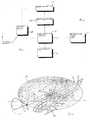
- Figure 1 is a block diagram of the relations among the basic components of the lighting device according to the present invention.
- Figures 2-4 illustrate the basic components of the device according to the present invention, which is referred to hereinbelow as lighting device 20.
- lighting device 20 includes a light source 22.
- Light source 22 is connectable (either directly or preferably indirectly via a housing as further detailed below) to a helicopter blade end or tip 21 .
- Device 20 further includes a power source 24 .
- Power source 24 is connectable (either directly or preferably indirectly via a housing as further detailed below) to the helicopter blade end 21 and provides light source 22 with power for its operation.
- lighting device 20 further includes a background light sensor 26.
- Sensor 26 serves for limiting the operation of light source 22 to background light below a predetermined threshold value, e.g., below 1 - 50 Lux (twilight equals about 10 Lux, deep twilight equals about 10 lux).
- a predetermined threshold value e.g., below 1 - 50 Lux (twilight equals about 10 Lux, deep twilight equals about 10 lux).
- Sensor 26 is preferably a photoresistive sensor, which therefore includes a resistor having resistivity which depends on light level to which it is exposed.
- a suitable sensor is distributed by EG&G (U.S.), Cat. No. VT20N.
- Sensor 26 is alternatively a photodiode, e.g., a P.I.N photodiode.
- lighting device 20 further includes a centrifugal switch 28.
- Switch 28 serves for limiting light source 22 to operate only above a predetermined g force value, say 150-200 g .
- source 22 operates only when the motor of the helicopter rotates, typically upon flight, and power is saved.
- sensor 26 and switch 28 ensure that source 22 operates only when the motor of the helicopter is operated in the dark.
- a suitable centrifugal switch is distributed by Interia (Switzerland), Cat. No. 6UO-200.
- lighting device 20 further includes a magnetic field sensitive switch 30.
- Switch 30 is implemented such that it bypasses centrifugal switch 28 and serves for conducting maintenance functionality tests of light source 26 .
- Closing switch 30 is effected by providing a magnet in its proximity.
- a suitable magnetic field sensitive switch is the REED SWITCH which is distributed by Philips, Cat. No. RI-23AAA.
- lighting device 20 further includes an electronic control card 32, i.e., a P.C. board.
- Card 32 electronically communicates with the other components of device 20, ensuring their operation as herein described.
- a suitable card is distributed by International Technologies (Lasers) Ltd. (Israel) Cat. No. ITL473100100.
- the power source 24 is a battery 36.
- Battery 36 is oriented such that its pointed end 38 (as opposed to the flat end), which seals battery 36 during its manufacture, faces away from end 21 of the helicopter blade when assembled therein, such that g forces acting on the electrolyte within battery 36 will force the electrolyte away from pointed end 38, to prevent leakage therefrom of the electrolyte.
- Battery 36 is preferably engaged within a battery housing 37 which includes a spring 39 positioned away from blade end 21, such that it serves to maintain the contacts of battery 36 with housing 37 even under the high g forces developing.
- a battery housing 37 which includes a spring 39 positioned away from blade end 21, such that it serves to maintain the contacts of battery 36 with housing 37 even under the high g forces developing.
- the spring engaged the pointed end of the battery.
- battery 36 provides at least three volts (e.g., 3.6 volts) and at least 1500 milliampers hour.
- Battery 36 is preferably a lithium battery, most preferably a lithium thionylchloride battery.
- a suitable battery is a lithium 3.6 V AA battery, distributed by SAFT (France), Cat. No. LS14500, having a total weight of 15 grams. This battery is adapted to perform under a wide temperature range (-50 °C to +80 °C).
- light source 22 is an infrared light source, which emits in a wavelength detectable by night vision systems, e.g., in the near infrared spectral range, say between 750 and 900 nm, preferably 830 nm.
- An infrared light source is the preferred embodiment for military applications, wherein helicopters flying at night are preferably darkened, such that they are harder to detect and target.
- the light source may also emit in the visible spectral range (e.g., yellow or red light).
- light source 22 is detectable from 300 meters, either to the naked eye or when assisted with night vision systems (e.g., AN/AVS-6 - aviator night vision system, Litton, ITT defense (U.S.).
- night vision systems e.g., AN/AVS-6 - aviator night vision system, Litton, ITT defense (U.S.).
- Light source 22 is preferably selected and/or implemented such that it provides a vertical lighting angle ⁇ of, say about 30°, preferably between 0° and 30°, wherein 0° is defined as the rotation plane of the helicopter blades.
- Light source 22 is preferably further selected and/or implemented such that it a horizontal lighting angle ⁇ , which is wide enough to generate a ring of light when the blades are at maximal speed, e.g., 60° (see Figure 5).
- Light source 22 is preferably a semiconductor light source, most preferably a light emitting diode (LED), which produces light intensity of at least one milliwat, preferably at least 20, 30 or 40 milliwat. Suitable LEDs are distributed by Hitachi (Japan), Cat. No. HLP 20RG or 30RG or 40RG or Model C, 830 nm.
- LED light emitting diode
- light source 22 is preferably deployed such that it emits light upwardly and sideways, such that it is not visable from the ground.
- a second light source 22 connectable to helicopter blade end 21 and receiving power from power source 24 may be employed in a head to tail configuration with the first light source 22, such that device 20 is better viewable by other aircrafts.
- Another option to achieve substantially the same effect is to equip blade end 21 with a reflective surface positioned to reflect some of the light radiation emitted from a single light source in directions from which it is not directly perceived at any given moment.
- both power source 24 and light source 22, and in that respect all of the other components of device 20 as herein described, are selected resistible to g forces developing at helicopter blade end 21 when rotated at maximal speed, e.g., 1200 g force.
- lighting device 20 further includes a housing 34 .
- Housing 34 is connectable to helicopter blade end 21 and serves for holding light source 22, power source 24 and other components of device 20, as applicable.
- Housing 34 preferably includes a cover 48 removably attachable thereto, such that access to power source 24 is allowed, e.g., for easy replacement of source 24 when exhausted.
- housing 34 is filled with a hardened molded substance 35 (see Figure 3).
- Substance 35 serves for supporting and protecting power source 24 and other components within housing 34 against g forces and vibrations associated with helicopter rotor operation.
- Housing 34 is formed with an opening 50 positioned above sensor 26 for allowing sensor 26 to sense the level of background light radiation.
- Housing 34 is preferably formed with a special protruding habitat 37 which serves for holding and securing light source 22, such that when device 20 is implemented over blade end 21, source 22 is elevated and therefore rendered more detectable by other aircrafts.
- housing 34 is shaped and designed acceptable by a recession 23 formed in blade end 21, such that the level to which device 20 protrudes from the surface of the blade is minimized, so that the aerodynamic properties of the blade are affected to a minimum degree as possible.
- Both housing 34 and the blade are provided with screw holes 52 to assist in screwing device 20 and the blade together. Further attachments may, for example, include adhesives resistible to the g forces developing upon rotor rotation. Examples include, but are not limited to, LOCTITE by Loctite Inc., U.S.
- recession 23 is formed in a cover element 27 which is designed to replace a conventional cover (not shown) of the weights housing typically deployed in helicopter blade ends.
- the overall weight of device 20 is selected low, e.g., about or below 100 ⁇ 1 grams, such that the functionality of the blade will be minorly affected.
- FIG. 5 shows a helicopter 60 having a body 62 and a rotor 64 connected via a shaft 65 on top thereto.
- Rotor 64 includes two blades 66, one of which is equipped with lighting device 20.
- the lighting effect is of a light ring 67 having a radius which is dictated by the distance in which device 20 is implemented with respect to rotor axes 65.
- angles ⁇ and ⁇ are selected as described above, light ring 67 is undetectable from the ground.
- FIG. 6 shows an electric circuit 70 which is suitable for device 20 as described herein with respect to its preferred embodiments.
- Circuit 70 includes a printed circuit board (PCB) driver, wherein W1 to W8 are connection terminals.
- Circuit 70 includes a power source S which is preferably a lithium battery of 3.6 volts, a centrifugal switch (marked as SW2 or "G” switch), one or two light emitting diodes ( LED1 and LED2), a magnetic field sensitive switch marked as SW1 , photoresistive sensor marked as LDR1 and a transistor Q4 which functions as a current switch.
- PCB printed circuit board
- the negative pole (-) of lithium battery S is connected to circuit 70 via connection W4 , which serves as a common ground for circuit 70.
- the positive pole (+) of lithium battery S is connected via terminal W3 to switch SW2 and switch SW1 which are parallel connected normally open switches. When either of switches SW2 or SW1 is closed, current is able to be drawn by consumers LED1 and/or LED2 of circuit 70 .
- Capacitor C13 functions as a high frequency filter to protect circuit 70 from electrical spikes that may cause improper operation and/or damage.
- Transistor Q4, sensor LDR1 and resistor R1 are functioning as a current switch which is sensitive to an ambient light.
- sensor LDR1 When sensor LDR1 is exposed to light, its resistance drops and as a result transistor Q4 cannot supply LED1 and/or LED2 with current.
- Resistors R3 and R4 serve for current adjustment for the operation of LED1 and/or LED2. It is clear that circuit 70 is not intended to be limiting, rather to serve as a simple example.
Landscapes
- Engineering & Computer Science (AREA)
- Aviation & Aerospace Engineering (AREA)
- Circuit Arrangement For Electric Light Sources In General (AREA)
- Catching Or Destruction (AREA)
Description
- The present invention relates to a lighting device and, more particularly, to an autonomous lighting device for helicopter blade end (tip).
- A helicopter (chopper) is an aircraft that is lifted and sustained in the air horizontally by rotating wings or blades turning on vertical axes through power supplied by an engine.
- Helicopters are used for civil, military and law enforcement applications. Some heavy helicopters are adapted to carry dozens of passengers (e.g., worriers) and their equipment.
- In some cases, helicopters fly in a close formation which includes a pair or more of helicopters, under low visibility conditions (e.g., at a dark night), which increases the chances of a collision between closely navigating helicopters.
- Indeed, in 1997, two Israeli helicopters of a pair formation crashed in the north of Israel due to collision therebetween causing the death of all 72 crew and passengers.
- US 3,174,552 discloses a light source for a rotary wing aircraft which is energised by an alternator driven by an air driven spinner carried by the rotary wing. The preamble of claim 1 is based on this document.
- Helicopter blade end lighting systems are known for several years. Such systems include a light source which receives power from the main power source of the aircraft. These prior art systems are controlled by the pilot from the cockpit. As such, these systems are wired both to the cockpit and to the main power source via sliding contacts at the rotor's shaft.
- However, in modem helicopters, such as but not limited to, BLACKHAWK, COBRA, APACHE, wiring between the blades and the aircraft's body is not feasible, since in such helicopters the blades are each a bulk of composite material and has no inner cavity adapted for wiring, and further since such helicopters lack sliding contacts at the rotor's shaft.
- There is thus a widely recognised need for, and it would be highly advantageous to have, an autonomous helicopter blade end lighting device.
- According to one aspect, the present invention consists in a helicopter rotor blade with an autonomous helicopter blade end lighting device, comprising a light source connected to a free end of a helicopter blade, and a power source connected to said helicopter blade end for providing said light source with power for operation, characterised in that said power source comprises a battery which is oriented such that g-forces, acting on an electrolyte within said battery, force said electrolyte away from a sealing end of said battery thereby preventing leakage of said electrolyte from said battery.
- According to another aspect, the present invention consists in a method of lighting a helicopter blade end comprising the step of attaching an autonomous lighting device to the free end of the helicopter blade, said autonomous lighting device including a light source being connectable to said helicopter blade end, and a power source being connectable to said helicopter blade end for providing said light source with power for operation, the power source comprising a battery which is orientated such that g-forces, acting on an electrolyte within said battery, force said electrolyte away from a sealing end of said battery thereby preventing leakage of said electrolyte from said battery.
- According to the described preferred embodiments the device further comprises a housing connected to the helicopter blade end, the housing holding the light source and the power source.
- The battery may be oriented such that its pointed end faces away from the end of the blade.
- According to an embodiment the battery provides at least three volts and at least 1500 milliampers hour.
- According to still further features in the described preferred embodiments the battery is a lithium battery.
- According to still further features in the described preferred embodiments the battery is a lithium thionylchloride battery.
- According to still further features in the described preferred embodiments the power source and the light source are resistible to g forces developing at the helicopter blade end when rotated.
- According to still further features in the described preferred embodiments the power source and the light source are resistible to 1200 g force.
- According to still further features in the described preferred embodiments the light source is an infrared light source.
- According to still further features in the described preferred embodiments the infrared light source emits in a wavelength detectable by night vision systems.
- According to still further features in the described preferred embodiments the infrared light source emits in a wavelength between 750 and 900 nm.
- According to still further features in the described preferred embodiments the light source is detectable from 300 meters.
- According to still further features in the described preferred embodiments the light source provides a beam of about 30° in vertical width.
- According to still further features in the described preferred embodiments the light source is a semiconductor light source.
- According to still further features in the described preferred embodiments the light source is a light emitting diode.
- According to still further features in the described preferred embodiments the light emitting diode emits at 750-900 nm.
- According to still further features in the described preferred embodiments the light source produces light intensity of at least one milliwat, preferably at least 20 milliwat.
- According to still further features in the described preferred embodiments the device further comprising a background light sensor for limiting the operation of the light source to background light below a predetermined threshold.
- According to still further features in the described preferred embodiments the background light sensor is resistible to g forces developing at the helicopter blade end when rotated.
- According to still further features in the described preferred embodiments the background light sensor is a photoresistive sensor.
- According to still further features in the described preferred embodiments the device further comprising a centrifugal switch for limiting the light source to operate only above a predetermined g force value.
- According to still further features in the described preferred embodiments the predetermined g force value is 150-200 g.
- According to still further features in the described preferred embodiments the device further comprising a magnetic field sensitive switch bypassing the centrifugal switch, magnetic field sensitive switch serves for conducting maintenance functionality tests of the light source.
- According to still further features in the described preferred embodiments the housing includes a hardened molded substance for supporting and protecting the power source against g forces and vibrations.
- According to still further features in the described preferred embodiments the device further comprising a second light source connectable to the helicopter blade end and receiving power from the power source, the light sources being arranged tail to tail.
- According to still further features in the described preferred embodiments the device weights less than 100 grams.
- The present invention successfully addresses the shortcomings of the presently known configurations by providing an autonomous, self powered, helicopter blade end lighting device which operates only when the rotor of the helicopter rotates in the dark. Additional preferred features and advantages of the lighting system according to the present invention will become apparent to one ordinarily skilled in the art from the following descriptions.
- The invention herein described, by way of example only, with reference to the accompanying drawings, wherein:
- FIG. 1 is a block diagram describing the components of the autonomous lighting device for helicopter blade according to the present invention;
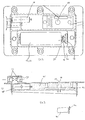
- FIG. 2 is a top view of the autonomous lighting device according to the present invention;
- FIG. 3 is a cross sectional view of the autonomous lighting device according to the present invention;
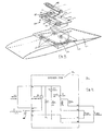
- FIG. 4 is a perceptive view of the autonomous lighting device according to the present invention and of an end of a helicopter blade designed to accept the device;
- FIG. 5 is a perspective view of a helicopter supplemented with the autonomous lighting device according to the present invention and serves to demonstrate preferred lighting effects; and
- FIG. 6 is a schematic depiction of an electrical circuit of the autonomous lighting device according to the present invention.
-
- The present invention is of an autonomous lighting device for helicopter blade end which can be used to render the rotor of the helicopter detectable by a pilot of a second helicopter in a formation. Specifically, the present invention can be used to reduce the chances of a collision between helicopters flying in close formation.
- The principles and operation of a lighting device according to the present invention may be better understood with reference to the drawings and accompanying descriptions.
- Before explaining at least one embodiment of the invention in detail, it is to be understood that the invention is not limited in its application to the details of construction and the arrangement of the components set forth in the following description or illustrated in the drawings. The invention is capable of other embodiments or of being practiced or carried out in various ways. Also, it is to be understood that the phraseology and terminology employed herein is for the purpose of description and should not be regarded as limiting.
- Referring now to the drawings, Figure 1 is a block diagram of the relations among the basic components of the lighting device according to the present invention. Figures 2-4 illustrate the basic components of the device according to the present invention, which is referred to hereinbelow as
lighting device 20. - Thus,
lighting device 20 includes alight source 22.Light source 22 is connectable (either directly or preferably indirectly via a housing as further detailed below) to a helicopter blade end ortip 21.Device 20 further includes apower source 24.Power source 24 is connectable (either directly or preferably indirectly via a housing as further detailed below) to thehelicopter blade end 21 and provideslight source 22 with power for its operation. - According to a preferred embodiment of the present
invention lighting device 20 further includes abackground light sensor 26.Sensor 26 serves for limiting the operation oflight source 22 to background light below a predetermined threshold value, e.g., below 1 - 50 Lux (twilight equals about 10 Lux, deep twilight equals about 10 lux). As a result,source 22 operates only when required and power is saved. -
Sensor 26 is preferably a photoresistive sensor, which therefore includes a resistor having resistivity which depends on light level to which it is exposed. A suitable sensor is distributed by EG&G (U.S.), Cat. No. VT20N.Sensor 26 is alternatively a photodiode, e.g., a P.I.N photodiode. - According to another preferred embodiment of the present
invention lighting device 20 further includes acentrifugal switch 28.Switch 28 serves for limitinglight source 22 to operate only above a predetermined g force value, say 150-200 g. As a result,source 22 operates only when the motor of the helicopter rotates, typically upon flight, and power is saved. - Thus, when in combination,
sensor 26 and switch 28 ensure thatsource 22 operates only when the motor of the helicopter is operated in the dark. A suitable centrifugal switch is distributed by Interia (Switzerland), Cat. No. 6UO-200. - According to another preferred embodiment of the present
invention lighting device 20 further includes a magnetic field sensitive switch 30. Switch 30 is implemented such that it bypassescentrifugal switch 28 and serves for conducting maintenance functionality tests oflight source 26. Closing switch 30 is effected by providing a magnet in its proximity. A suitable magnetic field sensitive switch is the REED SWITCH which is distributed by Philips, Cat. No. RI-23AAA. - According to yet another preferred embodiment of the present
invention lighting device 20 further includes anelectronic control card 32, i.e., a P.C. board.Card 32 electronically communicates with the other components ofdevice 20, ensuring their operation as herein described. A suitable card is distributed by International Technologies (Lasers) Ltd. (Israel) Cat. No. ITL473100100. - The
power source 24 is a battery 36. Battery 36 is oriented such that its pointed end 38 (as opposed to the flat end), which seals battery 36 during its manufacture, faces away fromend 21 of the helicopter blade when assembled therein, such that g forces acting on the electrolyte within battery 36 will force the electrolyte away frompointed end 38, to prevent leakage therefrom of the electrolyte. - Battery 36 is preferably engaged within a
battery housing 37 which includes aspring 39 positioned away fromblade end 21, such that it serves to maintain the contacts of battery 36 withhousing 37 even under the high g forces developing. Thus, in sharp distinction from prior art battery housing wherein the spring engages the flat end of the battery, according to the present invention the spring engaged the pointed end of the battery. - According to a prefered embodiment of the present invention battery 36 provides at least three volts (e.g., 3.6 volts) and at least 1500 milliampers hour. Battery 36 is preferably a lithium battery, most preferably a lithium thionylchloride battery. A suitable battery is a lithium 3.6 V AA battery, distributed by SAFT (France), Cat. No. LS14500, having a total weight of 15 grams. This battery is adapted to perform under a wide temperature range (-50 °C to +80 °C).
- According to a preferred embodiment of the invention
light source 22 is an infrared light source, which emits in a wavelength detectable by night vision systems, e.g., in the near infrared spectral range, say between 750 and 900 nm, preferably 830 nm. - An infrared light source is the preferred embodiment for military applications, wherein helicopters flying at night are preferably darkened, such that they are harder to detect and target. However, as the scope of the present invention is not limited to military applications, the light source may also emit in the visible spectral range (e.g., yellow or red light).
- According to a prefered embodiment
light source 22 is detectable from 300 meters, either to the naked eye or when assisted with night vision systems (e.g., AN/AVS-6 - aviator night vision system, Litton, ITT defense (U.S.). -
Light source 22 is preferably selected and/or implemented such that it provides a vertical lighting angle α of, say about 30°, preferably between 0° and 30°, wherein 0° is defined as the rotation plane of the helicopter blades.Light source 22 is preferably further selected and/or implemented such that it a horizontal lighting angle β, which is wide enough to generate a ring of light when the blades are at maximal speed, e.g., 60° (see Figure 5). -
Light source 22 is preferably a semiconductor light source, most preferably a light emitting diode (LED), which produces light intensity of at least one milliwat, preferably at least 20, 30 or 40 milliwat. Suitable LEDs are distributed by Hitachi (Japan), Cat. No. HLP 20RG or 30RG or 40RG or Model C, 830 nm. - Especially for military applications,
light source 22 is preferably deployed such that it emits light upwardly and sideways, such that it is not visable from the ground. - As shown in Figure 3, a second
light source 22 connectable tohelicopter blade end 21 and receiving power frompower source 24 may be employed in a head to tail configuration with thefirst light source 22, such thatdevice 20 is better viewable by other aircrafts. Another option to achieve substantially the same effect is to equip blade end 21 with a reflective surface positioned to reflect some of the light radiation emitted from a single light source in directions from which it is not directly perceived at any given moment. - In any case, both
power source 24 andlight source 22, and in that respect all of the other components ofdevice 20 as herein described, are selected resistible to g forces developing athelicopter blade end 21 when rotated at maximal speed, e.g., 1200 g force. - According to another preferred embodiment of the present
invention lighting device 20 further includes ahousing 34.Housing 34 is connectable tohelicopter blade end 21 and serves for holdinglight source 22,power source 24 and other components ofdevice 20, as applicable. -
Housing 34 preferably includes acover 48 removably attachable thereto, such that access topower source 24 is allowed, e.g., for easy replacement ofsource 24 when exhausted. - According to a preferred embodiment of the
present invention housing 34 is filled with a hardened molded substance 35 (see Figure 3).Substance 35 serves for supporting and protectingpower source 24 and other components withinhousing 34 against g forces and vibrations associated with helicopter rotor operation. -
Housing 34 is formed with anopening 50 positioned abovesensor 26 for allowingsensor 26 to sense the level of background light radiation. -
Housing 34 is preferably formed with a special protrudinghabitat 37 which serves for holding and securinglight source 22, such that whendevice 20 is implemented overblade end 21,source 22 is elevated and therefore rendered more detectable by other aircrafts. - As shown in Figure 4,
housing 34 is shaped and designed acceptable by arecession 23 formed inblade end 21, such that the level to whichdevice 20 protrudes from the surface of the blade is minimized, so that the aerodynamic properties of the blade are affected to a minimum degree as possible. - Both
housing 34 and the blade are provided withscrew holes 52 to assist in screwingdevice 20 and the blade together. Further attachments may, for example, include adhesives resistible to the g forces developing upon rotor rotation. Examples include, but are not limited to, LOCTITE by Loctite Inc., U.S. - According to a
preferred embodiment recession 23 is formed in acover element 27 which is designed to replace a conventional cover (not shown) of the weights housing typically deployed in helicopter blade ends. - According to a preferred embodiment of the present invention the overall weight of
device 20 is selected low, e.g., about or below 100±1 grams, such that the functionality of the blade will be minorly affected. - Figure 5 shows a helicopter 60 having a body 62 and a rotor 64 connected via a shaft 65 on top thereto. Rotor 64 includes two blades 66, one of which is equipped with
lighting device 20. - When rotor 64 rotates, the lighting effect is of a
light ring 67 having a radius which is dictated by the distance in whichdevice 20 is implemented with respect to rotor axes 65. When angles α and β are selected as described above,light ring 67 is undetectable from the ground. - Figure 6 shows an electric circuit 70 which is suitable for
device 20 as described herein with respect to its preferred embodiments. - Circuit 70 includes a printed circuit board (PCB) driver, wherein W1 to W8 are connection terminals. Circuit 70 includes a power source S which is preferably a lithium battery of 3.6 volts, a centrifugal switch (marked as SW2 or "G" switch), one or two light emitting diodes (LED1 and LED2), a magnetic field sensitive switch marked as SW1, photoresistive sensor marked as LDR1 and a transistor Q4 which functions as a current switch.
- The negative pole (-) of lithium battery S is connected to circuit 70 via connection W4, which serves as a common ground for circuit 70. The positive pole (+) of lithium battery S is connected via terminal W3 to switch SW2 and switch SW1 which are parallel connected normally open switches. When either of switches SW2 or SW1 is closed, current is able to be drawn by consumers LED1 and/or LED2 of circuit 70.
- Capacitor C13 functions as a high frequency filter to protect circuit 70 from electrical spikes that may cause improper operation and/or damage.
- Transistor Q4, sensor LDR1 and resistor R1 are functioning as a current switch which is sensitive to an ambient light. When sensor LDR1 is exposed to light, its resistance drops and as a result transistor Q4 cannot supply LED1 and/or LED2 with current. Resistors R3 and R4 serve for current adjustment for the operation of LED1 and/or LED2. It is clear that circuit 70 is not intended to be limiting, rather to serve as a simple example.
- Although the invention has been described in conjunction with specific embodiments thereof, it is evident that many alternatives, modifications and variations will be apparent to those skilled in the art. Accordingly, it is intended to embrace all such alternatives, modifications and variations that fall within the scope of the appended claims.
Claims (26)
- A helicopter rotor blade with an autonomous helicopter blade end lighting device, comprising a light source (22) connected to a free end (21) of the helicopter blade (22), and a power source (24) connected to said helicopter blade end (21) for providing said light source with power for operation, characterised in that said power source (24) comprises a battery (36) which is oriented such that g-forces, acting on an electrolyte within said battery, force said electrolyte away from a sealing end of said battery thereby preventing leakage of said electrolyte from said battery.
- A helicopter rotor blade of claim 1, including a housing (34) connected to said helicopter blade end (21), said housing (34) holding said light source (22) and said power source (24).
- A helicopter rotor blade as claimed in claim 1 or 2, wherein said battery (36) provides at least three volts and at least 1500 milliamperes hour.
- A helicopter rotor blade as claimed in claim 1, 2 or 3, wherein said battery (36) is a lithium battery.
- A helicopter rotor blade as claimed in claim 1, 2 or 3, wherein said battery (36) is a lithium thionylchloride battery.
- A helicopter rotor blade as claimed in any one of the preceding claims, wherein said power source (24) and said light source (22) are resistible to g-forces developing at said helicopter blade end (21) when rotated.
- A helicopter rotor blade as claimed in claim 6, wherein said power source (24) and said light source (22) are resistible to 1200 g-force.
- A helicopter rotor blade as claimed in any preceding claim, wherein said light source (22) is an infrared light source (22).
- A helicopter rotor blade as claimed in claim 8, wherein said infrared light source (22) emits in a wavelength detectable by night vision systems.
- A helicopter rotor blade as claimed in claim 8 or 9, wherein said infrared light source (22) emits in a wavelength between 750 and 900 nm.
- A helicopter rotor blade as claimed in any one of the preceding claims, wherein said light source (22) is detectable from 300 meters.
- A helicopter rotor blade as claimed in any one of the preceding claims, wherein said light source (22) provides a beam of about 30° in vertical width.
- A helicopter rotor blade as claimed in any one of the preceding claims, wherein said light source (22) is a semiconductor light source (22).
- A helicopter rotor blade as claimed in claim 13, wherein said light source (22) is a light emitting diode (22).
- A helicopter rotor blade as claimed in claim 14, wherein said light emitting diode emits at 750-900 nm.
- A helicopter rotor blade of claim 1, wherein said light source produces light intensity of at least one milliwatt.
- A helicopter rotor blade as claimed in any one of the preceding claims, including a background light sensor (26) for limiting the operation of said light source (22) to background light below a predetermined threshold.
- A helicopter rotor blade as claimed in claim 17, wherein said background light sensor (26) is resistible to g-forces developing at said helicopter blade end (21) when rotated.
- A helicopter rotor blade as claimed in claim 17 or 18, wherein said background light sensor (26) is a photoresistive sensor (26).
- A helicopter rotor blade as claimed in any one of the preceding claims, including a centrifugal switch (28) for limiting said light source (22) to operate only above a predetermined g force value.
- A helicopter rotor blade as claimed in claim 20, wherein said predetermined g force value is 150-200 g.
- A helicopter rotor blade as claimed in claim 20 or 21, including a magnetic field sensitive switch (30) bypassing said centrifugal switch (28), the magnetic field sensitive switch serving for conducting maintenance functionality tests of said light source (22).
- A helicopter rotor blade as claimed in claim 2, wherein said housing (34) includes a hardened molded substance for supporting and protecting said power source (24) against g forces and vibrations.
- A helicopter rotor blade as claimed in any one of the preceding claims, including a second light source (22) connected to said helicopter blade end (21) and receiving power from said power source (24), said light sources (22) being arranged tail to tail.
- A helicopter rotor blade as claimed in claim 1, weighing less than 100 grams.
- A method of lighting a helicopter blade end comprising the step of attaching an autonomous lighting device (20) to the free end of the helicopter blade, said autonomous lighting device including a light source (22) being connectable to said helicopter blade end (21), and a power source (24) being connectable to said helicopter blade end (21) for providing said light source (22) with power for operation, the power source (24) comprising a battery which is orientated such that g-forces, acting on an electrolyte within said battery, force said electrolyte away from a sealing end of said battery thereby preventing leakage of said electrolyte from said battery.
Applications Claiming Priority (2)
| Application Number | Priority Date | Filing Date | Title |
|---|---|---|---|
| US09/035,891 US6048172A (en) | 1998-03-06 | 1998-03-06 | Autonomous helicopter blade end lighting device |
| US35891 | 1998-03-06 |
Publications (3)
| Publication Number | Publication Date |
|---|---|
| EP0947423A2 EP0947423A2 (en) | 1999-10-06 |
| EP0947423A3 EP0947423A3 (en) | 2000-01-05 |
| EP0947423B1 true EP0947423B1 (en) | 2004-05-26 |
Family
ID=21885400
Family Applications (1)
| Application Number | Title | Priority Date | Filing Date |
|---|---|---|---|
| EP99301653A Expired - Lifetime EP0947423B1 (en) | 1998-03-06 | 1999-03-05 | Autonomous helicopter blade end lighting device |
Country Status (4)
| Country | Link |
|---|---|
| US (1) | US6048172A (en) |
| EP (1) | EP0947423B1 (en) |
| DE (1) | DE69917520T2 (en) |
| IL (1) | IL128606A (en) |
Families Citing this family (17)
| Publication number | Priority date | Publication date | Assignee | Title |
|---|---|---|---|---|
| RU2205775C1 (en) * | 2002-02-18 | 2003-06-10 | Открытое акционерное общество "Казанский вертолётный завод" | Aeronautical light warning system for helicopter |
| US7326435B2 (en) * | 2002-07-22 | 2008-02-05 | Defense Holdings, Inc. | Method of illuminating a rotary blade by application of a photoluminescent paint |
| US20050046195A1 (en) * | 2003-08-28 | 2005-03-03 | Kousoulis Theodore P. | Motor vehicle with wind generator device |
| DE102004048217B4 (en) | 2004-09-30 | 2007-04-19 | Eurocopter Deutschland Gmbh | Aircraft with cabin differential pressure warning system |
| US20070009357A1 (en) * | 2005-07-05 | 2007-01-11 | Solak David M | LED fan clip giving circular light bar during fan operation |
| US7324016B1 (en) | 2005-11-22 | 2008-01-29 | The United States Of America As Represented By The Secretary Of The Navy | Navigational indicating system for rotary wing aircraft |
| US7854590B2 (en) * | 2007-03-12 | 2010-12-21 | Bell Helicopter Textron Inc. | Rotor blade visual lights |
| EP2152575B1 (en) | 2007-03-12 | 2012-05-16 | Bell Helicopter Textron Inc. | Rotor blade visual lights |
| DE202008008517U1 (en) | 2008-06-27 | 2008-08-28 | Eurocopter Deutschland Gmbh | Energy self-sufficient lighting system for rotor blade tips, helicopters with such a lighting system and energy collector for it |
| WO2011119458A1 (en) | 2010-03-23 | 2011-09-29 | Bell Helicopter Textron Inc. | Swashplate-mounted permanent magnet alternator |
| EP3072813B1 (en) * | 2015-03-27 | 2020-01-15 | Goodrich Lighting Systems GmbH | Helicopter light system with layer material arranged on a rotor blade tip of the helicopter and helicopter comprising the same |
| CN106005457B (en) * | 2016-05-06 | 2018-04-10 | 哈尔滨飞机工业集团有限责任公司 | A kind of anticollision beacon mounting bracket |
| DE102016213720A1 (en) | 2016-07-26 | 2018-02-01 | Zf Friedrichshafen Ag | System for data transmission and processing for controlling a rotor blade actuator |
| US10875664B1 (en) * | 2019-06-28 | 2020-12-29 | Hamilton Sunstrand Corporation | Propeller tip warning marker light |
| EP3998216A4 (en) * | 2019-07-12 | 2022-08-17 | Koito Manufacturing Co., Ltd. | Aircraft lighting unit |
| CN115723956B (en) * | 2022-11-30 | 2025-08-08 | 四川沃飞长空科技发展有限公司 | Lighting systems and aircraft |
| US12221226B2 (en) * | 2023-04-06 | 2025-02-11 | Textron Aviation Inc. | Contactless power generator for powering lights on a propeller |
Family Cites Families (11)
| Publication number | Priority date | Publication date | Assignee | Title |
|---|---|---|---|---|
| US2423528A (en) * | 1944-07-12 | 1947-07-08 | Everett R Stewart | Helicopter navigation light |
| US2555807A (en) * | 1946-08-08 | 1951-06-05 | Gyrodyne Company Of America In | Wing tip light for rotary wing aircraft |
| US3174552A (en) * | 1963-12-09 | 1965-03-23 | Charles Adair | Rotary wing aircraft |
| US3395875A (en) * | 1965-10-22 | 1968-08-06 | Daniel R. Donovan | Wireless wingtip lights for rotary wing aircraft |
| IL33446A (en) * | 1969-11-28 | 1972-10-29 | Israel Aircraft Ind Ltd | Helicopter lighting system and light units useful therein |
| US3723722A (en) * | 1970-09-14 | 1973-03-27 | Dyonics Inc | Helicopter lighting |
| US3846023A (en) * | 1973-03-05 | 1974-11-05 | Us Army | Range reticle in a night vision device |
| US4066890A (en) * | 1976-09-24 | 1978-01-03 | The United States Of America As Represented By The Secretary Of The Army | Rotor tip light control |
| US4916581A (en) * | 1988-05-04 | 1990-04-10 | Authier Ricky J | Rotor blade illumination device |
| US5685637A (en) * | 1995-09-08 | 1997-11-11 | Jimmy G. Cook | Dual spectrum illumination system |
| US5793164A (en) * | 1996-09-17 | 1998-08-11 | Authier; Ricky J. | Low intensity aircraft rotor tip illumination |
-
1998
- 1998-03-06 US US09/035,891 patent/US6048172A/en not_active Expired - Lifetime
-
1999
- 1999-02-18 IL IL12860699A patent/IL128606A/en not_active IP Right Cessation
- 1999-03-05 DE DE69917520T patent/DE69917520T2/en not_active Expired - Fee Related
- 1999-03-05 EP EP99301653A patent/EP0947423B1/en not_active Expired - Lifetime
Also Published As
| Publication number | Publication date |
|---|---|
| IL128606A0 (en) | 2001-10-31 |
| DE69917520D1 (en) | 2004-07-01 |
| DE69917520T2 (en) | 2005-06-23 |
| IL128606A (en) | 2003-09-17 |
| EP0947423A3 (en) | 2000-01-05 |
| US6048172A (en) | 2000-04-11 |
| EP0947423A2 (en) | 1999-10-06 |
Similar Documents
| Publication | Publication Date | Title |
|---|---|---|
| US6048172A (en) | Autonomous helicopter blade end lighting device | |
| EP0736453B1 (en) | Aircraft lighting system | |
| US5124892A (en) | Hand mounted aviation night vision illuminating device | |
| US6693556B1 (en) | Enhanced visibility traffic signal | |
| US5862727A (en) | Laser arbor | |
| KR100398008B1 (en) | Electronically configurable towed decoy for dispensing infrared emitting flares | |
| US8534861B2 (en) | Mountable multi-function multi-mode marker/signaling device | |
| US6963293B1 (en) | System and method of preventing aircraft wingtip ground incursion | |
| US4862164A (en) | Infrared aircraft landing system | |
| EP3572334B1 (en) | Multi-mode aircraft navigation light and aircraft comprising the same | |
| EP3501993B1 (en) | Exterior aircraft light and aircraft comprising the same | |
| US4884275A (en) | Laser safety shutoff system | |
| US20160362193A1 (en) | Aircraft propeller warning illuminator | |
| EP3922564B1 (en) | Propeller tip warning marker light | |
| WO2002058032A1 (en) | Airplane warning sphere for day and night | |
| CN215475788U (en) | Luminous paddle | |
| US7721993B2 (en) | Wire-strike defence system | |
| Dornheim | Apache tests power of new cockpit tool | |
| EP2152575B1 (en) | Rotor blade visual lights | |
| KR0130653B1 (en) | Visual alarm | |
| CN222247637U (en) | Load Control Devices and Onboard Loads | |
| US7259685B2 (en) | Landing light fault annunciator | |
| CA2337057C (en) | Enhanced visibility traffic signal | |
| CN115285366A (en) | Luminous paddle | |
| US20220315249A1 (en) | Aviation equipment illumination personnel protection system |
Legal Events
| Date | Code | Title | Description |
|---|---|---|---|
| PUAI | Public reference made under article 153(3) epc to a published international application that has entered the european phase |
Free format text: ORIGINAL CODE: 0009012 |
|
| AK | Designated contracting states |
Kind code of ref document: A2 Designated state(s): DE FR GB IT |
|
| AX | Request for extension of the european patent |
Free format text: AL;LT;LV;MK;RO;SI |
|
| PUAL | Search report despatched |
Free format text: ORIGINAL CODE: 0009013 |
|
| AK | Designated contracting states |
Kind code of ref document: A3 Designated state(s): AT BE CH CY DE DK ES FI FR GB GR IE IT LI LU MC NL PT SE |
|
| AX | Request for extension of the european patent |
Free format text: AL;LT;LV;MK;RO;SI |
|
| 17P | Request for examination filed |
Effective date: 20000609 |
|
| AKX | Designation fees paid |
Free format text: DE FR GB IT |
|
| 17Q | First examination report despatched |
Effective date: 20021227 |
|
| GRAP | Despatch of communication of intention to grant a patent |
Free format text: ORIGINAL CODE: EPIDOSNIGR1 |
|
| GRAS | Grant fee paid |
Free format text: ORIGINAL CODE: EPIDOSNIGR3 |
|
| GRAA | (expected) grant |
Free format text: ORIGINAL CODE: 0009210 |
|
| AK | Designated contracting states |
Kind code of ref document: B1 Designated state(s): DE FR GB IT |
|
| REG | Reference to a national code |
Ref country code: GB Ref legal event code: FG4D |
|
| REF | Corresponds to: |
Ref document number: 69917520 Country of ref document: DE Date of ref document: 20040701 Kind code of ref document: P |
|
| ET | Fr: translation filed | ||
| PLBE | No opposition filed within time limit |
Free format text: ORIGINAL CODE: 0009261 |
|
| STAA | Information on the status of an ep patent application or granted ep patent |
Free format text: STATUS: NO OPPOSITION FILED WITHIN TIME LIMIT |
|
| 26N | No opposition filed |
Effective date: 20050301 |
|
| REG | Reference to a national code |
Ref country code: FR Ref legal event code: CD |
|
| PGFP | Annual fee paid to national office [announced via postgrant information from national office to epo] |
Ref country code: GB Payment date: 20090325 Year of fee payment: 11 |
|
| PGFP | Annual fee paid to national office [announced via postgrant information from national office to epo] |
Ref country code: IT Payment date: 20090323 Year of fee payment: 11 Ref country code: DE Payment date: 20090320 Year of fee payment: 11 |
|
| PGFP | Annual fee paid to national office [announced via postgrant information from national office to epo] |
Ref country code: FR Payment date: 20090312 Year of fee payment: 11 |
|
| GBPC | Gb: european patent ceased through non-payment of renewal fee |
Effective date: 20100305 |
|
| REG | Reference to a national code |
Ref country code: FR Ref legal event code: ST Effective date: 20101130 |
|
| PG25 | Lapsed in a contracting state [announced via postgrant information from national office to epo] |
Ref country code: FR Free format text: LAPSE BECAUSE OF NON-PAYMENT OF DUE FEES Effective date: 20100331 |
|
| PG25 | Lapsed in a contracting state [announced via postgrant information from national office to epo] |
Ref country code: DE Free format text: LAPSE BECAUSE OF NON-PAYMENT OF DUE FEES Effective date: 20101001 |
|
| PG25 | Lapsed in a contracting state [announced via postgrant information from national office to epo] |
Ref country code: GB Free format text: LAPSE BECAUSE OF NON-PAYMENT OF DUE FEES Effective date: 20100305 Ref country code: IT Free format text: LAPSE BECAUSE OF NON-PAYMENT OF DUE FEES Effective date: 20100305 |