EP0947360A2 - Tyre removal machine and relative accessories - Google Patents
Tyre removal machine and relative accessories Download PDFInfo
- Publication number
- EP0947360A2 EP0947360A2 EP98204141A EP98204141A EP0947360A2 EP 0947360 A2 EP0947360 A2 EP 0947360A2 EP 98204141 A EP98204141 A EP 98204141A EP 98204141 A EP98204141 A EP 98204141A EP 0947360 A2 EP0947360 A2 EP 0947360A2
- Authority
- EP
- European Patent Office
- Prior art keywords
- wheel rim
- machine
- platform
- rod
- tyre
- Prior art date
- Legal status (The legal status is an assumption and is not a legal conclusion. Google has not performed a legal analysis and makes no representation as to the accuracy of the status listed.)
- Granted
Links
- 239000011324 bead Substances 0.000 claims description 26
- 230000037431 insertion Effects 0.000 claims 2
- 238000003780 insertion Methods 0.000 claims 2
- 239000000284 extract Substances 0.000 description 2
- 238000000034 method Methods 0.000 description 1
- 238000012986 modification Methods 0.000 description 1
- 230000004048 modification Effects 0.000 description 1
- 238000011017 operating method Methods 0.000 description 1
Images


Classifications
-
- B—PERFORMING OPERATIONS; TRANSPORTING
- B60—VEHICLES IN GENERAL
- B60C—VEHICLE TYRES; TYRE INFLATION; TYRE CHANGING; CONNECTING VALVES TO INFLATABLE ELASTIC BODIES IN GENERAL; DEVICES OR ARRANGEMENTS RELATED TO TYRES
- B60C25/00—Apparatus or tools adapted for mounting, removing or inspecting tyres
- B60C25/01—Apparatus or tools adapted for mounting, removing or inspecting tyres for removing tyres from or mounting tyres on wheels
- B60C25/05—Machines
- B60C25/132—Machines for removing and mounting tyres
- B60C25/135—Machines for removing and mounting tyres having a tyre support or a tool, movable along wheel axis
- B60C25/138—Machines for removing and mounting tyres having a tyre support or a tool, movable along wheel axis with rotary motion of tool or tyre support
-
- B—PERFORMING OPERATIONS; TRANSPORTING
- B60—VEHICLES IN GENERAL
- B60C—VEHICLE TYRES; TYRE INFLATION; TYRE CHANGING; CONNECTING VALVES TO INFLATABLE ELASTIC BODIES IN GENERAL; DEVICES OR ARRANGEMENTS RELATED TO TYRES
- B60C25/00—Apparatus or tools adapted for mounting, removing or inspecting tyres
- B60C25/01—Apparatus or tools adapted for mounting, removing or inspecting tyres for removing tyres from or mounting tyres on wheels
- B60C25/05—Machines
- B60C25/053—Support of wheel parts during machine operation
- B60C25/0542—Support of wheel parts during machine operation with self-centering means, e.g. cones
Definitions
- This invention concerns machines for mounting and removing a tyre on and from its wheel rim, and in particular relates both to machines able to adapt to all currently available types of tyre and wheel rim, and to the optional accessories with which known machines can be provided.
- Special tyres are known which ensure that the vehicle is able to travel even under low pressure conditions, ie when the tyre inflation pressure is very low or close to zero, as happens in the case of a puncture, such tyres being known hereinafter simply as special tyres.
- These special tyres comprise not only the external carcass but also a separate toroidal support ring of elastomeric rubber, which is housed in an appropriate seat provided in the wheel rim well.
- both the wheel rim and the tyre are constructed with special profiles.
- the special tyre has different diameters at its beads, with the result that the wheel rim is not symmetrical about the plane passing through its centre, and furthermore comprises seats for receiving the different-diameter beads.
- the beads of the special tyre have a much smaller thickness than those of known tyres, and are hence less resistant to mechanical stresses and more fragile than known beads.
- Said group of accessories for tyre removal machines of traditional type comprises:
- FIG. 1 shows the tyre removal machine indicated overall by 1 and comprising a base 2, from the upper surface 20 of which there emerges the shaft 100 of an electric motor, not shown, on which a usual self-centering device 3 is positioned. From the rear of the base 2 there extends a column 4, the end of which terminates with a tube 5 of horizontal axis having an internal prismatic cross-section within which a bar 6 slides.
- the front end of said prismatic bar 6 supports a sleeve 7 of vertical axis within which there slides a bar 8 of prismatic cross-section, to the lower end of which there is fixed the traditional tool 9 for removing the tyre P. Sliding of the bars 6 and 8 is facilitated by suitable counter-weights or springs, the bars being locked in their seats generally by constriction means.
- Said rod 11 forms the guide element for a vertically slidable tubular member 12 on which there is mounted in a vertically slidable manner a second tubular member 13 upperly provided with a sleeve 14 of horizontal axis extending in a direction substantially radial to the self-centering device 3.
- Said sleeve 14 is arranged to receive a prismatic bar 15, to the end of which there is fixed a plate 17 on which two frusto-conical rollers 18 and 19 are idly and opposingly mounted, their function being to urge the beads 300 and 301 (or side walls) of the tyre into the seats 403 and 400 respectively of the wheel rim C.
- the self-centering device is provided with four identical radially slidable jaws 30 arranged to grip the edge of a wheel rim of traditional type.
- the jaws 30 grip a disc 24 provided with a central hub 240 of vertical axis and having a through hole 241 traversed by a diametrical pin 242 receiving a rod 25.
- the rod 25 has both its ends fork-shaped by virtue of the presence of a slot 240 for receiving the pin 242 of the hub 240. At about half way along its length, the rod 25 also supports a cup member 26 forming a circular ledge, on which there rests the disc 27 of the wheel rim C, as shown in Figure 2.
- the wheel rim c is maintained rigid with the rod 25 by virtue of the cone member 28 and nut 29, of quick-locking type, which by being screwed onto the threaded portion 251 of the rod 25 maintains the member 28 in the position shown in Figure 2.
- the operator mounts onto the wheel rim C that bead 300 of the tyre P which is of greater diameter and the toroidal support ring S, after which by means of the cylinder-piston unit 23 the rollers 18 and 19 are brought into contact with the bead 301 of the tyre P.
- the self-centering device 3 is rotated, the pressure exerted by the rollers 18 and 19 against the bead 301 of the tyre P then urging the bead 301 into the appropriate seat 400 of the wheel rim C.
- the support S moves until it rests against the relief edge 401 of the wheel rim C, and the bead 300 moves into its well 402.
- the operator extracts a portion of the bead 300 from the wheel rim C to create a gap between the bead 300 and the edge 404 of the wheel rim, into which gap he inserts the tool 9, after which he rotates the self-centering device to cause the entire bead 300 to withdraw from the wheel rim C, into the position shown in Figure 7.
- the bead 300 lies above the edge of the wheel rim.
- the operator has to insert the bead 300 into the seat 403 of the wheel rim C.
- the cylinder-piston unit 23 is operated to move the rollers 18 and 19 into contact with the bead 300 of the tyre P, the self-centering device 3 is rotated, and the pressure exerted by the rollers on the bead 300 forces it into the appropriate seat 403 of the wheel rim C.
- the tyre is removed from the wheel rim in the following manner:
- the hub 240 can be mounted directly on the shaft 100 without interposing the self-centering device 3, in which case the resultant tyre removal machine is able to operate only on the described type of special tyre.
Landscapes
- Engineering & Computer Science (AREA)
- Mechanical Engineering (AREA)
- Tires In General (AREA)
- Testing Of Balance (AREA)
- Automatic Assembly (AREA)
- Cleaning In General (AREA)
Abstract
Description
- This invention concerns machines for mounting and removing a tyre on and from its wheel rim, and in particular relates both to machines able to adapt to all currently available types of tyre and wheel rim, and to the optional accessories with which known machines can be provided.
- Special tyres are known which ensure that the vehicle is able to travel even under low pressure conditions, ie when the tyre inflation pressure is very low or close to zero, as happens in the case of a puncture, such tyres being known hereinafter simply as special tyres.
- These special tyres comprise not only the external carcass but also a separate toroidal support ring of elastomeric rubber, which is housed in an appropriate seat provided in the wheel rim well.
- To enable the tyre and the toroidal support ring to be mounted on the wheel rim, both the wheel rim and the tyre are constructed with special profiles.
- Specifically, the special tyre has different diameters at its beads, with the result that the wheel rim is not symmetrical about the plane passing through its centre, and furthermore comprises seats for receiving the different-diameter beads. In addition the beads of the special tyre have a much smaller thickness than those of known tyres, and are hence less resistant to mechanical stresses and more fragile than known beads.
- These new special tyres are described in French patent applications FR 92/15061 and FR 93/14702.
- To remove or mount these special tyres from or onto the wheel rim a procedure has to be used which cannot be followed by tyre removal machines of traditional type, because of the asymmetry of the tyre beads and the need to insert the toroidal ring.
- Attempts to construct specific tyre removal machines for this type of tyre have been unsuccessful both for reasons of cost and because of the particular operating methods required.
- The problem is solved according to this invention, by the provision of simple modifications to traditional machines and/or a group of accessories provided therewith.
- Said group of accessories for tyre removal machines of traditional type comprises:
- a first assembly of removable means for receiving and fixing the wheel rim,
- means to be fixed to the rotary platform of the machine, to receive said wheel rim fixing means,
- means drivable in the direction of the wheel rim axis and arranged to press against the side of the tyre.
- The operational and constructional characteristics of the invention will be more apparent from the ensuing description of a preferred embodiment thereof given by way of non-limiting example and illustrated on the accompanying drawings.
- Figure 1 is a side view of a tyre removal machine on which the accessories of this invention are installed.
- Figure 2 is a partly sectional view of the accessories of the invention in a first working position.
- Figure 3 is a partly sectional view of the accessories of the invention in a second working position.
- Figure 4 is an enlarged detailed view of the means for pressing against the side of the tyre.
- Figures 5, 6, 7, 8 show the steps involved in mounting the special tyre onto the wheel rim using the accessories of the invention.
-
- Said figures show the tyre removal machine indicated overall by 1 and comprising a
base 2, from theupper surface 20 of which there emerges theshaft 100 of an electric motor, not shown, on which a usual self-centering device 3 is positioned. From the rear of thebase 2 there extends a column 4, the end of which terminates with atube 5 of horizontal axis having an internal prismatic cross-section within which abar 6 slides. With reference to Figure 1, the front end of saidprismatic bar 6 supports asleeve 7 of vertical axis within which there slides abar 8 of prismatic cross-section, to the lower end of which there is fixed thetraditional tool 9 for removing the tyre P. Sliding of thebars - On the
lateral surface 21 of thebase 2 there is applied ahorizontal plate 10 from which arod 11 upwardly extends. - Said
rod 11 forms the guide element for a vertically slidabletubular member 12 on which there is mounted in a vertically slidable manner a secondtubular member 13 upperly provided with asleeve 14 of horizontal axis extending in a direction substantially radial to the self-centering device 3. Saidsleeve 14 is arranged to receive aprismatic bar 15, to the end of which there is fixed aplate 17 on which two frusto-conical rollers beads 300 and 301 (or side walls) of the tyre into theseats - Between the
plate 10 and the upper end of thetubular member 13 there is interposed a double-acting cylinder-piston unit 23, of which the rod is hinged to thetubular member 13 and the cylinder is hinged to theplate 10 as shown in Figure 1. - The assembly and the operation of the aforedescribed parts is illustrated in patent application RE93U000040 in the name of the present applicant.
- The self-centering device is provided with four identical radially
slidable jaws 30 arranged to grip the edge of a wheel rim of traditional type. - According to the invention the
jaws 30 grip adisc 24 provided with acentral hub 240 of vertical axis and having a throughhole 241 traversed by adiametrical pin 242 receiving arod 25. - Specifically, the
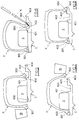
rod 25 has both its ends fork-shaped by virtue of the presence of aslot 240 for receiving thepin 242 of thehub 240. At about half way along its length, therod 25 also supports acup member 26 forming a circular ledge, on which there rests thedisc 27 of the wheel rim C, as shown in Figure 2. - The wheel rim c is maintained rigid with the
rod 25 by virtue of thecone member 28 andnut 29, of quick-locking type, which by being screwed onto the threadedportion 251 of therod 25 maintains themember 28 in the position shown in Figure 2. - The operations to be carried out to mount the tyre P on the wheel rim C using the accessories of the invention are illustrated in Figures 5, 6, 7, 8.
- Having rigidly locked the wheel rim C to the tyre removal machine 1 by the aforesaid means, and with the smaller-diameter edge facing upwards, the operator mounts onto the wheel rim C that bead 300 of the tyre P which is of greater diameter and the toroidal support ring S, after which by means of the cylinder-
piston unit 23 therollers bead 301 of the tyre P. At this point the self-centering device 3 is rotated, the pressure exerted by therollers bead 301 of the tyre P then urging thebead 301 into theappropriate seat 400 of the wheel rim C. Simultaneously the support S moves until it rests against therelief edge 401 of the wheel rim C, and thebead 300 moves into itswell 402. - Having done this the operator inverts the wheel rim into the position shown in Figure 3, ie with the greater-diameter edge facing upwards.
- To achieve this he raises the wheel rim while fixed to the
rod 25, inverts the whole piece and reinserts the other end of therod 25 into thehub 240 of thedisc 24. - When in this position the operator extracts the
bead 301 from thewell 402 in the wheel rim C and moves it outside the wheel rim as shown in Figures 6 and 7. - Using a suitable lever, the operator extracts a portion of the
bead 300 from the wheel rim C to create a gap between thebead 300 and theedge 404 of the wheel rim, into which gap he inserts thetool 9, after which he rotates the self-centering device to cause theentire bead 300 to withdraw from the wheel rim C, into the position shown in Figure 7. - As a result of this inversion, the
bead 300 lies above the edge of the wheel rim. - To complete the mounting of the tyre P onto the wheel rim C the operator has to insert the
bead 300 into theseat 403 of the wheel rim C. To achieve this the cylinder-piston unit 23 is operated to move therollers bead 300 of the tyre P, the self-centering device 3 is rotated, and the pressure exerted by the rollers on thebead 300 forces it into theappropriate seat 403 of the wheel rim C. - The tyre is removed from the wheel rim in the following manner:
- the tyre is deflated,
- the wheel rim and
rod 25 are inserted into thehub 240 with the smaller-diameter bead facing upwards, with reference to Figure 2, - using the cylinder-
piston unit 23 therollers bead 301 of the tyre P. At this point, by pressing against the bead edge with therollers bead 301 from the wheel rim C, - the wheel is then inverted in the aforesaid manner,
- the
rollers device 3 is rotated to move thebead 300 beyond therelief edge 401, - at this point the tyre P leaves the wheel rim C.
- It should be noted that the
hub 240 can be mounted directly on theshaft 100 without interposing the self-centering device 3, in which case the resultant tyre removal machine is able to operate only on the described type of special tyre.
Claims (9)
- A machine for removing and mounting tyres from and onto their wheel rim, comprising a platform rotating on a base and provided with self-centering jaws for locking the wheel rim; a vertical column close to said platform and extending from the base; means projectingly supported by said column and movable in the manner of a normal tyre removal tool both radially and vertically relative to the platform, and lockable in position; at least one substantially horizontal arm movable vertically relative to the column and lockable in position; and actuator means arranged to raise and lower said arm; characterised in that the central hub of the rotary platform comprises, coaxial with the platform, a cylindrical cavity provided with a transverse pin and arranged to receive one of the two ends of a rod provided with means for fixing and supporting the wheel rim.
- A machine as claimed in claim 1, characterised by comprising a disc provided with a central hub, the cylindrical cavity of which is provided with a transverse pin and is arranged to receive one of the two ends of a rod provided with means for fixing and supporting the wheel rim.
- A machine as claimed in the preceding claims, characterised in that said rod has both its ends tapered and fork-shaped for its insertion into the cavity of said hub and for receiving within said fork the transverse pin of said hub.
- A machine as claimed in the preceding claims, characterised in that said rod comprises in its central region a circular ledge and a threaded portion adjacent thereto, to receive a centering cone and a quick-manipulation nut.
- A machine as claimed in the preceding claims, characterised in that at the end of said vertically movable arm there is provided a pair of idle conical rollers with their axes converging towards the central axis of the rotary platform, and which by pressing against the side of the tyre form a gap between the bead and the edge of the wheel rim such as to enable the usual bead raising tool to be inserted.
- A machine as claimed in claim 5, characterised in that said vertically movable arm carries only one idle roller, the axis of which is close to the central axis of the rotary platform.
- A group of accessories for a tyre removal machine, comprising a disc able to be locked onto the self-centering means of the usual rotary platform of the tyre removal machine, and provided with a central hub, the cylindrical cavity of which is provided with a transverse pin and is arranged to receive one of the two ends of a rod provided with means for fixing and supporting the wheel rim.
- A group as claimed in claim 7, characterised in that the means for fixing and supporting the wheel rim comprise a rod having both its ends tapered and forked-shaped for its insertion into the cavity of said hub and for receiving within said fork the transverse pin of said hub.
- A group as claimed in claim 8, characterised in that said rod comprises in its central region a circular ledge and a threaded portion adjacent thereto, to receive a centering cone and a quick-manipulation nut.
Applications Claiming Priority (2)
| Application Number | Priority Date | Filing Date | Title |
|---|---|---|---|
| ITRE980035 | 1998-04-02 | ||
| IT1998RE000035A IT1304273B1 (en) | 1998-04-02 | 1998-04-02 | TIRE CHANGER MACHINE AND RELATED ACCESSORIES. |
Publications (3)
| Publication Number | Publication Date |
|---|---|
| EP0947360A2 true EP0947360A2 (en) | 1999-10-06 |
| EP0947360A3 EP0947360A3 (en) | 2000-07-12 |
| EP0947360B1 EP0947360B1 (en) | 2003-06-11 |
Family
ID=11399212
Family Applications (1)
| Application Number | Title | Priority Date | Filing Date |
|---|---|---|---|
| EP98204141A Expired - Lifetime EP0947360B1 (en) | 1998-04-02 | 1998-12-08 | Tyre removal machine and relative accessories |
Country Status (5)
| Country | Link |
|---|---|
| US (1) | US6240995B1 (en) |
| EP (1) | EP0947360B1 (en) |
| JP (1) | JP3716117B2 (en) |
| DE (1) | DE69815497T2 (en) |
| IT (1) | IT1304273B1 (en) |
Cited By (10)
| Publication number | Priority date | Publication date | Assignee | Title |
|---|---|---|---|---|
| EP0987130A3 (en) * | 1998-09-14 | 2003-05-14 | Societa'Italiana Costruzioni Elettromeccaniche-S.I.C.E-S.P.A. | Device for tyre removal machines |
| EP1916125A1 (en) * | 2006-10-27 | 2008-04-30 | C.M.L. s.n.c. di Marco Galbiati & C. | Operating head for a tyre-removal machine and associated tyre-removal machine |
| WO2008080584A3 (en) * | 2007-01-04 | 2008-09-25 | Michael Immler | Mounting device, and method for mounting and dismounting a vehicle tire on and from a rim |
| US7438110B2 (en) | 2006-11-03 | 2008-10-21 | Kia Motors Corporation | Tire mounting apparatus |
| ITVR20090069A1 (en) * | 2009-05-19 | 2010-11-20 | Butler Eng & Marketing | BREAKER GROUP FOR MOUNT-TIRE CHANGER MACHINE |
| ITMI20102213A1 (en) * | 2010-11-29 | 2012-05-30 | Pogliani & Rivolta S P A | TIGHTENING DEVICE OF A RIM ON AN EQUIPMENT TO ASSEMBLE / DISASSEMBLE A TIRE ON / FROM THE SAME RIM AND ITS APPARATUS FOR ASSEMBLING / DISASSEMBLING A TIRE INCLUDING SUCH A TIGHTENING DEVICE |
| ITBO20110300A1 (en) * | 2011-05-24 | 2012-11-25 | Corghi Spa | A CENTERING DEVICE FOR THE RIM OF A WHEEL ON THE WHEEL-HOLDING ASSEMBLY OF A TIRE CHANGER MACHINE. |
| CN104527344A (en) * | 2014-12-29 | 2015-04-22 | 营口光明科技有限公司 | Tire bead separator arranged on manipulator of tire changer |
| WO2016042445A1 (en) * | 2014-09-15 | 2016-03-24 | Corghi S.P.A. | Device and method for locking a rim of a wheel to a turntable |
| CN112297724A (en) * | 2020-11-24 | 2021-02-02 | 中意泰达(营口)汽车保修设备有限公司 | Novel tire dismounting device |
Families Citing this family (17)
| Publication number | Priority date | Publication date | Assignee | Title |
|---|---|---|---|---|
| US6374975B1 (en) * | 1999-02-25 | 2002-04-23 | Raphael Schlanger | Movable torque coupling element for the transmission of torque between two colinear shafts |
| IT1319467B1 (en) * | 2000-05-22 | 2003-10-10 | Corghi Spa | RIM LOCKING DEVICE FOR TIRE CHANGING MACHINES |
| US7814641B2 (en) | 2001-01-09 | 2010-10-19 | Black & Decker Inc. | Method of forming a power tool |
| US7096566B2 (en) | 2001-01-09 | 2006-08-29 | Black & Decker Inc. | Method for making an encapsulated coil structure |
| US6840522B2 (en) * | 2003-05-01 | 2005-01-11 | Thomas Merrifield | Method and apparatus for repairing automobile wheel |
| DE202004006462U1 (en) * | 2004-04-23 | 2005-09-01 | Jungheinrich Aktiengesellschaft | Conveyor with attachment |
| DE102004044287B3 (en) * | 2004-09-10 | 2005-08-25 | Warkotsch, Horst | Quick release fastener e.g. for attachment to vehicle wheel on balancing machine, has flange for connecting to rim of vehicle wheel and clamp for tightening rim against flange with cone has internal drill for pushing onto balancing machine |
| US7343955B2 (en) * | 2005-12-28 | 2008-03-18 | Hennessy Industries, Inc. | Tire changing machine |
| US20100089257A1 (en) * | 2006-02-27 | 2010-04-15 | Entire Solutions Ltd | Apparatus for, and methods of, compacting a tyre part |
| US8307874B1 (en) | 2008-01-25 | 2012-11-13 | Hunter Engineering Company | Tire changing method and machine with angularly positionable drive axis |
| US8567453B2 (en) * | 2009-12-09 | 2013-10-29 | Android Industries Llc | Apparatus, methods, components, and systems for assembling and/or inflating a tire-wheel assembly |
| US20130192768A1 (en) * | 2012-01-31 | 2013-08-01 | Chih-Liang Peng | Structure of tire changer |
| ES2620974T3 (en) * | 2015-03-12 | 2017-06-30 | Corghi S.P.A. | Wheel service machine and method for locking a wheel to a wheel support unit |
| CN105150779B (en) * | 2015-09-30 | 2017-04-12 | 池学建 | Wheel rim clamp ring dismounting device and dismounting method thereof |
| CN106827980B (en) * | 2017-03-07 | 2019-08-16 | 科维(营口)工业有限公司 | A kind of the Pneumatic elevation slide plate and tire changer of tire changer |
| CN109017171A (en) * | 2018-08-03 | 2018-12-18 | 常州信息职业技术学院 | A kind of liftable tire auxiliary repair apparatus |
| CN110203013B (en) * | 2019-06-27 | 2023-11-24 | 中信戴卡股份有限公司 | High-precision assembling device for wheels |
Citations (3)
| Publication number | Priority date | Publication date | Assignee | Title |
|---|---|---|---|---|
| FR2699121A1 (en) | 1992-12-11 | 1994-06-17 | Michelin & Cie | Set formed by a tire, a rim and a support ring. |
| ITRE930040U1 (en) | 1993-05-21 | 1994-11-21 | Corghi Spa | Bead breaker device for tire changer machines. |
| FR2713558A1 (en) | 1993-12-08 | 1995-06-16 | Michelin & Cie | Pneumatic, rim, support ring and assembly comprising said elements. |
Family Cites Families (12)
| Publication number | Priority date | Publication date | Assignee | Title |
|---|---|---|---|---|
| GB578761A (en) * | 1951-05-29 | 1946-07-10 | Dunlop Rubber Co | An improved apparatus for removing tyres from wheels |
| DE2648897C2 (en) * | 1976-10-28 | 1982-10-07 | Wilhelm 6349 Herbornseelbach Schäfer | Machine for assembling and disassembling vehicle tires |
| US4738294A (en) * | 1986-10-16 | 1988-04-19 | Fosse Clarence A | Device for changing tubeless truck tires |
| IT1210394B (en) * | 1987-03-09 | 1989-09-14 | Corghi Elettromecc Spa | SELF-CENTERING UNIT FOR WHEEL BALANCING MACHINES FOR MOTOR VEHICLES |
| DE8800372U1 (en) * | 1988-01-14 | 1988-03-24 | Stahlgruber Otto Gruber GmbH & Co, 8000 MÜnchen | Tire changer |
| US5078193A (en) * | 1990-11-13 | 1992-01-07 | Discount Tire Co., Inc. | Wheelbarrow and trailer wheel apparatus |
| US5226465A (en) * | 1991-02-19 | 1993-07-13 | Stahlgruber Otto Gruber Gmbh & Co. | Mounting device for motor vehicle tires |
| DE59107435D1 (en) * | 1991-09-27 | 1996-03-28 | Schenck Auto Service Geraete | Method for connecting a rotatable mounting plate with a rotatable pin of a tire changer and complete tire changer and tire changer |
| US5332020A (en) * | 1992-11-05 | 1994-07-26 | Brunner Larry F | Tire changing apparatus |
| DK44893D0 (en) * | 1993-04-21 | 1993-04-21 | Hjort Hansen Arne | DEVICE AND REMOVAL DEVICE, NORMALLY LARGE TIRE |
| IT1262836B (en) * | 1993-09-09 | 1996-07-04 | Giuliano Vignoli | PNEUMATIC OPERATED TIRE CHANGER MACHINE. |
| IT1289137B1 (en) * | 1996-10-22 | 1998-09-25 | Butler Eng & Marketing | TIRE CHANGER MACHINE |
-
1998
- 1998-04-02 IT IT1998RE000035A patent/IT1304273B1/en active
- 1998-12-08 EP EP98204141A patent/EP0947360B1/en not_active Expired - Lifetime
- 1998-12-08 DE DE69815497T patent/DE69815497T2/en not_active Expired - Fee Related
- 1998-12-09 US US09/207,257 patent/US6240995B1/en not_active Expired - Fee Related
- 1998-12-24 JP JP36666998A patent/JP3716117B2/en not_active Expired - Fee Related
Patent Citations (3)
| Publication number | Priority date | Publication date | Assignee | Title |
|---|---|---|---|---|
| FR2699121A1 (en) | 1992-12-11 | 1994-06-17 | Michelin & Cie | Set formed by a tire, a rim and a support ring. |
| ITRE930040U1 (en) | 1993-05-21 | 1994-11-21 | Corghi Spa | Bead breaker device for tire changer machines. |
| FR2713558A1 (en) | 1993-12-08 | 1995-06-16 | Michelin & Cie | Pneumatic, rim, support ring and assembly comprising said elements. |
Cited By (20)
| Publication number | Priority date | Publication date | Assignee | Title |
|---|---|---|---|---|
| EP0987130A3 (en) * | 1998-09-14 | 2003-05-14 | Societa'Italiana Costruzioni Elettromeccaniche-S.I.C.E-S.P.A. | Device for tyre removal machines |
| EP1916125A1 (en) * | 2006-10-27 | 2008-04-30 | C.M.L. s.n.c. di Marco Galbiati & C. | Operating head for a tyre-removal machine and associated tyre-removal machine |
| US7438110B2 (en) | 2006-11-03 | 2008-10-21 | Kia Motors Corporation | Tire mounting apparatus |
| WO2008080584A3 (en) * | 2007-01-04 | 2008-09-25 | Michael Immler | Mounting device, and method for mounting and dismounting a vehicle tire on and from a rim |
| US8215366B2 (en) | 2007-01-04 | 2012-07-10 | Immler Michael | Mounting device, and method for mounting and dismounting a vehicle tire on and from a rim |
| US8714228B2 (en) | 2007-01-04 | 2014-05-06 | Robert Bosch Gmbh | Mounting device, and method for mounting and dismounting a vehicle tire on a wheel rim |
| ITVR20090069A1 (en) * | 2009-05-19 | 2010-11-20 | Butler Eng & Marketing | BREAKER GROUP FOR MOUNT-TIRE CHANGER MACHINE |
| EP2253488A1 (en) | 2009-05-19 | 2010-11-24 | Butler Engineering & Marketing S.p.A. | A bead breaker group for a tire mounting-demounting machine |
| US9126463B2 (en) | 2009-05-19 | 2015-09-08 | Butler Engineering & Marketing S.P.A. | Bead breaker group for a tire mounting-demounting machine |
| ITMI20102213A1 (en) * | 2010-11-29 | 2012-05-30 | Pogliani & Rivolta S P A | TIGHTENING DEVICE OF A RIM ON AN EQUIPMENT TO ASSEMBLE / DISASSEMBLE A TIRE ON / FROM THE SAME RIM AND ITS APPARATUS FOR ASSEMBLING / DISASSEMBLING A TIRE INCLUDING SUCH A TIGHTENING DEVICE |
| EP2527167A1 (en) * | 2011-05-24 | 2012-11-28 | CORGHI S.p.A. | Device for centring the rim of a wheel on the wheel-holder unit of a tyre changer machine |
| CN102795066A (en) * | 2011-05-24 | 2012-11-28 | 科希股份有限公司 | Device for centring the rim of a wheel on the wheel-holder unit of a tyre changer machine |
| ITBO20110300A1 (en) * | 2011-05-24 | 2012-11-25 | Corghi Spa | A CENTERING DEVICE FOR THE RIM OF A WHEEL ON THE WHEEL-HOLDING ASSEMBLY OF A TIRE CHANGER MACHINE. |
| US9180744B2 (en) | 2011-05-24 | 2015-11-10 | Corghi S.P.A. | Device for centring the rim of a wheel on the wheel-holder unit of a tyre changer machine |
| CN102795066B (en) * | 2011-05-24 | 2016-05-11 | 科希股份有限公司 | For on the wheel seat unit of tyre changing machines by wheel rim the device to center |
| WO2016042445A1 (en) * | 2014-09-15 | 2016-03-24 | Corghi S.P.A. | Device and method for locking a rim of a wheel to a turntable |
| US10245909B2 (en) | 2014-09-15 | 2019-04-02 | Nexion S.P.A. | Device and method for locking a rim of a wheel to a turntable |
| CN104527344A (en) * | 2014-12-29 | 2015-04-22 | 营口光明科技有限公司 | Tire bead separator arranged on manipulator of tire changer |
| CN112297724A (en) * | 2020-11-24 | 2021-02-02 | 中意泰达(营口)汽车保修设备有限公司 | Novel tire dismounting device |
| CN112297724B (en) * | 2020-11-24 | 2021-08-10 | 中意泰达(营口)汽车保修设备有限公司 | Novel tire dismounting device |
Also Published As
| Publication number | Publication date |
|---|---|
| EP0947360A3 (en) | 2000-07-12 |
| EP0947360B1 (en) | 2003-06-11 |
| JP3716117B2 (en) | 2005-11-16 |
| ITRE980035A1 (en) | 1999-10-02 |
| JPH11301226A (en) | 1999-11-02 |
| DE69815497D1 (en) | 2003-07-17 |
| DE69815497T2 (en) | 2003-12-18 |
| US6240995B1 (en) | 2001-06-05 |
| IT1304273B1 (en) | 2001-03-13 |
Similar Documents
| Publication | Publication Date | Title |
|---|---|---|
| EP0947360B1 (en) | Tyre removal machine and relative accessories | |
| US6619362B2 (en) | Automatic tyre removal and mounting device and tyre removal machines equipped therewith | |
| EP1052120B1 (en) | Multipurpose station for mounting and removing conventional and special tires | |
| EP1157860B2 (en) | Automatic bead release device for tyre removal machines | |
| EP1916125B1 (en) | Operating head for a tyre-removal machine and associated tyre-removal machine | |
| EP1048496B1 (en) | Tyre removal machine for tyres of "system pax" type and the like | |
| EP0644071B1 (en) | Pneumatically operated tyre removal machine | |
| EP1026017B1 (en) | Machine for mounting and removing special tires | |
| US6192959B1 (en) | Machine for fitting and removing tires | |
| US5836368A (en) | Machine for mounting and removing tires onto and from respective wheel rims | |
| US7946016B2 (en) | Method and machine for removing a tyre fitted with a rigid inner run-flat ring | |
| US20230123205A1 (en) | Machine for mounting and demounting a tyre relative to a corresponding rim and wheel servicing method | |
| EP0987130A2 (en) | Device for tyre removal machines | |
| EP1236589A2 (en) | Improved implement for demounting and mounting self-supporting tyres of the system pax type and the like | |
| JPH0747822A (en) | Bead release unit for tire removal machine to remove tire bead from wheel rim | |
| EP2905153B1 (en) | Tyre-changing machine | |
| KR20050014003A (en) | Method and unit for mounting on a rim a tyre provided with a safety support | |
| CN119546468A (en) | Wheel clamping systems for tire changing machines | |
| JPH0565362B2 (en) | ||
| CS215369B1 (en) | Dismantling and disguising equipment for tire treads during dismantling |
Legal Events
| Date | Code | Title | Description |
|---|---|---|---|
| PUAI | Public reference made under article 153(3) epc to a published international application that has entered the european phase |
Free format text: ORIGINAL CODE: 0009012 |
|
| AK | Designated contracting states |
Kind code of ref document: A2 Designated state(s): DE ES FR GB IT |
|
| AX | Request for extension of the european patent |
Free format text: AL;LT;LV;MK;RO;SI |
|
| PUAL | Search report despatched |
Free format text: ORIGINAL CODE: 0009013 |
|
| AK | Designated contracting states |
Kind code of ref document: A3 Designated state(s): AT BE CH CY DE DK ES FI FR GB GR IE IT LI LU MC NL PT SE |
|
| AX | Request for extension of the european patent |
Free format text: AL;LT;LV;MK;RO;SI |
|
| AKX | Designation fees paid |
Free format text: DE ES FR GB IT |
|
| 17P | Request for examination filed |
Effective date: 20000922 |
|
| 17Q | First examination report despatched |
Effective date: 20020617 |
|
| GRAH | Despatch of communication of intention to grant a patent |
Free format text: ORIGINAL CODE: EPIDOS IGRA |
|
| RAP1 | Party data changed (applicant data changed or rights of an application transferred) |
Owner name: CORGHI S.P.A. |
|
| GRAH | Despatch of communication of intention to grant a patent |
Free format text: ORIGINAL CODE: EPIDOS IGRA |
|
| GRAA | (expected) grant |
Free format text: ORIGINAL CODE: 0009210 |
|
| AK | Designated contracting states |
Designated state(s): DE ES FR GB IT |
|
| REG | Reference to a national code |
Ref country code: GB Ref legal event code: FG4D |
|
| REF | Corresponds to: |
Ref document number: 69815497 Country of ref document: DE Date of ref document: 20030717 Kind code of ref document: P |
|
| PG25 | Lapsed in a contracting state [announced via postgrant information from national office to epo] |
Ref country code: ES Free format text: LAPSE BECAUSE OF FAILURE TO SUBMIT A TRANSLATION OF THE DESCRIPTION OR TO PAY THE FEE WITHIN THE PRESCRIBED TIME-LIMIT Effective date: 20030922 |
|
| PG25 | Lapsed in a contracting state [announced via postgrant information from national office to epo] |
Ref country code: GB Free format text: LAPSE BECAUSE OF NON-PAYMENT OF DUE FEES Effective date: 20031208 |
|
| ET | Fr: translation filed | ||
| PLBE | No opposition filed within time limit |
Free format text: ORIGINAL CODE: 0009261 |
|
| STAA | Information on the status of an ep patent application or granted ep patent |
Free format text: STATUS: NO OPPOSITION FILED WITHIN TIME LIMIT |
|
| 26N | No opposition filed |
Effective date: 20040312 |
|
| GBPC | Gb: european patent ceased through non-payment of renewal fee |
Effective date: 20031208 |
|
| PGFP | Annual fee paid to national office [announced via postgrant information from national office to epo] |
Ref country code: DE Payment date: 20061114 Year of fee payment: 9 |
|
| PGFP | Annual fee paid to national office [announced via postgrant information from national office to epo] |
Ref country code: FR Payment date: 20061205 Year of fee payment: 9 |
|
| PGFP | Annual fee paid to national office [announced via postgrant information from national office to epo] |
Ref country code: IT Payment date: 20061231 Year of fee payment: 9 |
|
| PG25 | Lapsed in a contracting state [announced via postgrant information from national office to epo] |
Ref country code: DE Free format text: LAPSE BECAUSE OF NON-PAYMENT OF DUE FEES Effective date: 20080701 |
|
| REG | Reference to a national code |
Ref country code: FR Ref legal event code: ST Effective date: 20081020 |
|
| PG25 | Lapsed in a contracting state [announced via postgrant information from national office to epo] |
Ref country code: FR Free format text: LAPSE BECAUSE OF NON-PAYMENT OF DUE FEES Effective date: 20071231 |
|
| PG25 | Lapsed in a contracting state [announced via postgrant information from national office to epo] |
Ref country code: IT Free format text: LAPSE BECAUSE OF NON-PAYMENT OF DUE FEES Effective date: 20071208 |