EP0946883B1 - Verfahren und vorrichtung zum messen und prüfen von werkstücken - Google Patents
Verfahren und vorrichtung zum messen und prüfen von werkstücken Download PDFInfo
- Publication number
- EP0946883B1 EP0946883B1 EP97954440A EP97954440A EP0946883B1 EP 0946883 B1 EP0946883 B1 EP 0946883B1 EP 97954440 A EP97954440 A EP 97954440A EP 97954440 A EP97954440 A EP 97954440A EP 0946883 B1 EP0946883 B1 EP 0946883B1
- Authority
- EP
- European Patent Office
- Prior art keywords
- measuring
- probe
- feeler
- measurement
- frame
- Prior art date
- Legal status (The legal status is an assumption and is not a legal conclusion. Google has not performed a legal analysis and makes no representation as to the accuracy of the status listed.)
- Expired - Lifetime
Links
- 238000000034 method Methods 0.000 title claims description 14
- 239000000523 sample Substances 0.000 claims description 66
- 238000005259 measurement Methods 0.000 claims description 33
- 238000004519 manufacturing process Methods 0.000 claims description 20
- 230000003287 optical effect Effects 0.000 claims description 10
- 238000012546 transfer Methods 0.000 claims description 6
- 238000012360 testing method Methods 0.000 description 23
- 241001422033 Thestylus Species 0.000 description 3
- 238000005516 engineering process Methods 0.000 description 3
- 238000010521 absorption reaction Methods 0.000 description 2
- 230000008901 benefit Effects 0.000 description 2
- 230000008859 change Effects 0.000 description 2
- 238000010276 construction Methods 0.000 description 2
- 238000012937 correction Methods 0.000 description 2
- 238000013461 design Methods 0.000 description 2
- 230000006870 function Effects 0.000 description 2
- 241000881711 Acipenser sturio Species 0.000 description 1
- 230000000712 assembly Effects 0.000 description 1
- 238000000429 assembly Methods 0.000 description 1
- 239000002131 composite material Substances 0.000 description 1
- 230000006835 compression Effects 0.000 description 1
- 238000007906 compression Methods 0.000 description 1
- 238000011161 development Methods 0.000 description 1
- 230000018109 developmental process Effects 0.000 description 1
- 230000005670 electromagnetic radiation Effects 0.000 description 1
- 238000011156 evaluation Methods 0.000 description 1
- 238000012854 evaluation process Methods 0.000 description 1
- 238000012423 maintenance Methods 0.000 description 1
- 238000000691 measurement method Methods 0.000 description 1
- 239000012528 membrane Substances 0.000 description 1
- 230000015654 memory Effects 0.000 description 1
- 230000008569 process Effects 0.000 description 1
- 238000012545 processing Methods 0.000 description 1
- 238000003908 quality control method Methods 0.000 description 1
- 230000005855 radiation Effects 0.000 description 1
- 230000008439 repair process Effects 0.000 description 1
- 238000012552 review Methods 0.000 description 1
- 230000035945 sensitivity Effects 0.000 description 1
- 238000010998 test method Methods 0.000 description 1
Images



Classifications
-
- G—PHYSICS
- G01—MEASURING; TESTING
- G01B—MEASURING LENGTH, THICKNESS OR SIMILAR LINEAR DIMENSIONS; MEASURING ANGLES; MEASURING AREAS; MEASURING IRREGULARITIES OF SURFACES OR CONTOURS
- G01B5/00—Measuring arrangements characterised by the use of mechanical techniques
- G01B5/004—Measuring arrangements characterised by the use of mechanical techniques for measuring coordinates of points
- G01B5/008—Measuring arrangements characterised by the use of mechanical techniques for measuring coordinates of points using coordinate measuring machines
-
- B—PERFORMING OPERATIONS; TRANSPORTING
- B23—MACHINE TOOLS; METAL-WORKING NOT OTHERWISE PROVIDED FOR
- B23Q—DETAILS, COMPONENTS, OR ACCESSORIES FOR MACHINE TOOLS, e.g. ARRANGEMENTS FOR COPYING OR CONTROLLING; MACHINE TOOLS IN GENERAL CHARACTERISED BY THE CONSTRUCTION OF PARTICULAR DETAILS OR COMPONENTS; COMBINATIONS OR ASSOCIATIONS OF METAL-WORKING MACHINES, NOT DIRECTED TO A PARTICULAR RESULT
- B23Q17/00—Arrangements for observing, indicating or measuring on machine tools
- B23Q17/20—Arrangements for observing, indicating or measuring on machine tools for indicating or measuring workpiece characteristics, e.g. contour, dimension, hardness
-
- B—PERFORMING OPERATIONS; TRANSPORTING
- B25—HAND TOOLS; PORTABLE POWER-DRIVEN TOOLS; MANIPULATORS
- B25J—MANIPULATORS; CHAMBERS PROVIDED WITH MANIPULATION DEVICES
- B25J15/00—Gripping heads and other end effectors
- B25J15/0019—End effectors other than grippers
-
- B—PERFORMING OPERATIONS; TRANSPORTING
- B62—LAND VEHICLES FOR TRAVELLING OTHERWISE THAN ON RAILS
- B62D—MOTOR VEHICLES; TRAILERS
- B62D65/00—Designing, manufacturing, e.g. assembling, facilitating disassembly, or structurally modifying motor vehicles or trailers, not otherwise provided for
Definitions
- the invention relates to a method and a device for measuring and testing workpieces, especially of Body parts of vehicles with the features in General term of the process and Device main claim.
- DE-A-43 27 937 teaches such a method as well Device for measuring and checking objects.
- a test sample is used that has a probe, with which the object is touched. This button is rigid educated.
- the test sample is carried out by hand and served.
- a similar method and device is known from the WO-A-93/07443 known.
- a manually guided Measurement sample and an external optical protractor Spatial points with their spatial coordinates are recorded and measured.
- the test sample has several on the outside LEDs that function as position indicators and from Protractor can be optically detected.
- the test sample has one rigid and immovable button with which to measuring points in space.
- EP-A-0 390 648 shows another measuring method in addition to Device for measuring and checking the surface of Objects.
- a test sample on one in several translational axes movable sample holder arranged.
- the test sample has an axial and radial movable push button that is elastic by a membrane is held.
- the button is pressed over the surface of the Guided and palpated for unevenness or Differences in height, whereby he movements relative to Sample holder executes.
- the button movements are optoelectronically arranged in the interior of the measurement sample Measuring elements measured and evaluated.
- the invention solves this problem with the features in the main method and device claim.
- the measuring technique according to the invention is much less complex than the previously known coordinate machine. It is also less susceptible to errors because the robot's axis errors are not included in the measurement. This in turn makes it possible to carry out the measurement with relatively simple manipulators or robots and without increased precision requirements.
- Another advantage is the low sensitivity to interference of the measuring technology, which requires neither air-conditioned, nor sound and vibration-isolated measuring rooms.
- the measuring technology according to the invention is therefore special economically. But it also allows use within a manufacturing facility.
- the measurements can also at various points in the manufacturing process be made. This allows immediate Access to the causes of errors and also a subsequent one Correction of any errors found.
- the measuring technique can namely be used in an area where the Body parts or those from the individual parts composite body not yet fully solidified corrective interventions are permitted. The after An error occurs in subsequent manufacturing steps are still usable. The state of the art these follow-up steps when an error occurs early for free.
- the measuring points usually have a special geometric shape and consist of holes or bumps at which a Catch and center the correspondingly shaped button yourself can.
- high measuring accuracies are independent of robot guidance and its errors possible. In particular can take measurements at any measuring point on the workpiece be made, with only the test sample in the field of vision of the optical measurement system must be.
- the measuring technology according to the invention also does not represent high Operating and evaluation requirements. she can even with less qualified operators performed and possibly even automated become.
- the invention relates to a method and Measuring device (1) for measuring and checking workpieces (3).
- the workpieces (3) are preferably to body parts of vehicles, such as, for example shown in Figure 3 as part of the underbody group are.
- the body parts (3) are in one Manufacturing plant (19) manufactured, being in individual Manufacturing areas (20) from various individual parts Assemblies are manufactured.
- the subassemblies become then the finished body part, e.g. a complete Underbody, built up.
- Behind individual or all Manufacturing areas (20) is a measuring device (1) arranged to measure and test the here manufactured body part (3) before further loading and Processing enables.
- the measuring device (1) can in the production area (20) can be integrated.
- the transfer line (21) is the conveying area over which the workpieces (3) from one Production area (20) to the next production area (20) reach.
- the measuring device (1) can be in the transfer line (1) form your own station.
- the measuring device (1) is closer in Figures 1 and 2 shown and described.
- the workpiece (3) is in Figure 1 shown only schematically. It is in the realm of Measuring device (1) not shown in one Clamping device clamped exactly and has one here defined and known location.
- each workpiece (3) one or more defined measuring points (4). Based on Position of the measuring points (4) can be determined whether the workpiece (3) is true to size.
- the measuring points (4) can a reference for compliance with the given Form the geometry and the dimensions of the workpiece (3).
- the measuring point (4) e.g. around holes in the workpiece (3).
- the Measuring points (4) also towering pins or the like be e.g. Attachment points for other body parts form.
- the measuring device (1) consists of one or more Measurement samples (6) and an optical measurement system (17) and one or more manipulators (2). Both Manipulators (2) are preferably multi-axis industrial robots. In the embodiment a six-axis robot is shown.
- the test sample (6) is attached to the robot hand (5) and is by this led and moved.
- the measuring sample (6) is from the robot (2) to the measuring points (4) scheduled.
- the optical measurement system (17) consists of three linear measuring camera units in one housing are arranged side by side or one above the other and one have a fixed relationship to each other.
- the camera system (17) is able to change the position of the test sample (6) after six Record axes and measure them optically.
- a computing unit (18) is connected for this purpose.
- the Computing unit (18) is preferably a computer with a or multiple microprocessors, multiple data and Program memories and the necessary I / O units equipped.
- the Camera system (17) recorded positions of the test sample (6) calculated and from this the positions of the searched Measuring points (4) determined.
- the measurement and test results are also output by the computing unit (18) and in appropriately indicated, e.g. in the in Figure 3 shown table form with identification of the measuring points (4) and details of the deviations from the target position in the three translational spatial axes.
- the test sample (6) has at least one position indicator (8,9,10,11), preferably three or more position detectors. These are preferably switchable Light electrodes when they light up will change their position in the room by the units of the camera system (17) recorded and measured. Through the different Viewing angles of the three camera units can Positions of the position indicators (8,9,10,11) in the room exactly be determined. This is also the orientation of the Measuring sample (6) can be determined precisely. The recording and Surveying can be done point by point or at intervals done continuously at a high frequency, thereby if necessary also path movements of the test sample (6) can be determined.
- the optical measurement system (10) is in a known Location reference arranged. It is preferably in one known absolute spatial position and in a known Location relationship to the station's world coordinate system arranged, to which also the tensioning device, the Workpiece (3) and the robot (2) in a known Stand local relationship.
- the measurement system (10) measured position values of the position detectors (8,9,10,11,12) and the determined data of the measuring points (4) are preferably referred to as absolute location coordinates to the world coordinate system.
- the optical measurement system (10) is so in the station set up that it has as clear a field of vision as possible Workpiece (3) or the measuring points (4) and the measuring sample (6) Has.
- Latter can specify a reference to the station and exist e.g. from simple mechanical tips.
- test sample (6) e.g. from an L-shaped angled sample holder (12), at its striking corner or end points the Position detector (9,10,11) sit.
- the sample holder (12) can also have another suitable shape.
- the sample carrier (12) has a simplified Embodiment a button (14) which is rigid with the Sample carrier (12) is connected.
- the button (14) exists from a straight stylus (15) with a probe (16) at the end.
- the probe or the entire button (14) can be interchangeable.
- the probe (16) can e.g. as a ball, Cone tip, cone hat or in any other suitable manner be trained. Its shape depends on the shape the desired measuring point (4).
- the Probe (16) curves, bevels or the like other guiding surfaces, which an introduction or guidance on Make measuring point (4) easier.
- the test sample (6) can be a switch for actuating the Position indicators (9,10,11).
- a Line connection to the computing unit (18) or to Camera system (17) exist.
- Control commands can be sent via this switch are given to the computing unit (18), which e.g. For ensure that the recorded positions are saved.
- the computing unit (18) In order to can also carry out measurement or evaluation processes of the camera system (17) or the computing unit (18) by remote control be switched.
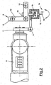
- the sample carrier (12) can be avoided with the Robotic hand (5) connected. There is evasion after one or more axes possible. Owns for this purpose the test sample (6) a frame (7) on the robot hand (5) is attached. The sample carrier (12) is over a Spring element (13) on the frame (7) in said manner stored evasively.
- the spring element (13) from a compression spring with a press plate, which the Surrounds the stylus (15) and the button (14) with the Press the sample holder (12) down against the frame (7).
- the frame (7) has a spring element (13) surrounding it Housing by moving the stylus (15) and also height with lateral play in two holes.
- a press plate be present inside the housing by the spring is pressed against the housing base.
- the spring element (13) there are different alternatives.
- Compressed air bellows or in any other suitable manner be designed to give the Push button (14) and the sample holder (12) when attaching to Allow workpiece (3).
- the manipulator (2) or Position error of the measuring point (4) corrected Due to the evasive storage of the sample holder (12) positioning errors the manipulator (2) or Position error of the measuring point (4) corrected.
- the Positional inaccuracies are usually relatively limited and less than the evasiveness of the button (14).
- the button (14) is in the Able to adapt itself to the shape of Probe (16) and measuring point (4) in the correct position to bring to the measuring point (4) and accordingly also the Align the sample holder (12).
- the position indicators (9,10,11) have a fixed and known relation to the probe (16). About measuring the The position of the position indicator (9,10,11) is exactly that Position of the probe (16) in the room can be determined. By the self-search function and the targetable as a result Hit accuracy or positioning accuracy at the measuring point (4) is the position of the measuring point (4) in the Space can be determined exactly.
- Position detector (8) can be arranged. It serves as a reference for the programmed target position of the robot hand (5) or the tool center point (TCP) or the probe (16). This position indicator (8) is used in the measurement also recorded. It has a certain spatial Assignment to the probe (16) in the rest or normal position the sample carrier (12) without deflection of the spring element (13). The deviation is also via the position indicator (8) the actual position of the measuring point (4) or the probe (16) from that in the path control of the manipulator (2) specified position can be determined.
Landscapes
- Engineering & Computer Science (AREA)
- Mechanical Engineering (AREA)
- Manufacturing & Machinery (AREA)
- Chemical & Material Sciences (AREA)
- Combustion & Propulsion (AREA)
- Transportation (AREA)
- Robotics (AREA)
- Physics & Mathematics (AREA)
- General Physics & Mathematics (AREA)
- Length Measuring Devices With Unspecified Measuring Means (AREA)
- Manipulator (AREA)
- A Measuring Device Byusing Mechanical Method (AREA)
Description
Die erfindungsgemäße Meßtechnik ist wesentlich weniger aufwendig als die vorbekannte Koordinatenmaschine. Sie ist auch in einem deutlich geringeren Umfang fehleranfällig, weil die Achsfehler des Roboters nicht in die Messung eingehen. Dies wiederum ermöglicht es, mit relativ einfachen Manipulatoren oder Robotern und ohne erhöhte Präzisionsanforderungen die Messung durchzuführen. Als weiterer Vorteil ist die geringe Störempfindlichkeit der Meßtechnik hervorzuheben, die weder klimatisierte, noch schall-und schwingungsisolierte Meßräume verlangt.
- Figur 1:
- Die Meßvorrichtung mit einem Werkstück in Seitenansicht,
- Figur 2:
- eine vergrößerte Darstellung der Roboterhand mit der Meßprobe,
- Figur 3:
- eine schematische Darstellung eines Werkstückes mit Meßpunkten und
- Figur 4:
- ein Schemaplan einer Rohbaufertigung im Rahmen der Unterbodenfertigung.
- 1
- Meßvorrichtung
- 2
- Manipulator, Roboter
- 3
- Werkstück, Karosserieteil
- 4
- Meßpunkt
- 5
- Roboterhand
- 6
- Meßprobe
- 7
- Gestell
- 8
- Postionsmelder, Referenz LED
- 9
- Postionsmelder, LED
- 10
- Postionsmelder, LED
- 11
- Postionsmelder, LED
- 12
- Probenträger
- 13
- Federelement
- 14
- Taster
- 15
- Taststift
- 16
- Tastkopf
- 17
- optisches Vermessungssystem, Kamerasystem
- 18
- Recheneinheit
- 19
- Fertigungsanlage
- 20
- Fertigungsbereich
- 21
- Transferlinie
Claims (11)
- Verfahren zum Messen und Prüfen von Werkstücken (3), insbesondere von Karosserieteilen von Fahrzeugen, wobei die Position von ein oder mehreren definierten Messpunkten (4) am Werkstück (3) vermessen wird und die Messung mit einer Meßprobe (6) durchgeführt wird, die einen Probenträger (12) mit einem Taster (14) und mit ein oder mehreren außenseitigen, optisch erfassbaren Positionsmeldern (8, 9, 10, 11) aufweist, wobei die Meßprobe (6) mit dem Taster (14) am Messpunkt (4) angesetzt wird und die Positionsmelder (8,9,10,11) zur Lagebestimmung von einem externen ortsbezogenen optischen Vermessungssystem (17) angemessen werden und hieraus die Position der Messpunkte (4) ermittelt wird, dadurch gekennzeichnet, dass die Meßprobe (6) von einem Manipulator (2) mit einer Roboterhand (5) an die Meßpunkte (4) des Werkstücks (3) mechanisch tastend angesetzt wird, wobei die Meßprobe (6) ein mit der Roboterhand (5) verbundenes Gestell (7) und den daran elastisch gelagerten Probenträger (12) aufweist und der Probenträger (12) vom Manipulator (2) mit einer elastischen Ausweichfähigkeit nach ein oder mehreren Achsen gegenüber der Roboterhand (5) gehalten wird, wobei der Taster (14) in der Form an die Gestalt der Messpunkte (4) angepasst wird und selbstfangend oder selbstzentrierend an die Messpunkte (4) angesetzt wird.
- Verfahren nach Anspruch 1, dadurch gekennzeichnet, dass die Messung innerhalb einer Fertigungsanlage (19) an ein oder mehreren Fertigungsbereichen (20) durchgeführt wird.
- Verfahren nach Anspruch 2, dadurch gekennzeichnet, dass die Messung im Anschluß an einen Fertigungsbereich (20) in der Transferlinie (21) durchgeführt wird.
- Vorrichtung zum Messen und Prüfen von Werkstücken (3), insbesondere von Karosserieteilen von Fahrzeugen, wobei die Position von ein oder mehreren definierten Messpunkten (4) am Werkstück (3) vermessen wird und wobei die Meßvorrichtung (1) mindestens eine Meßprobe (6) mit einem Probenträger (12), einem Taster (14) und ein oder mehreren außenseitigen, optisch erfassbaren Positionsmeldern (8,9,10,11) sowie ein externes ortsbezogenes optisches Vermessungssystem (17) mit einer Recheneinheit (18) aufweist, dadurch gekennzeichnet, dass ein Manipulator (2) mit einer Roboterhand (5) die Meßprobe (6) führt, wobei die Meßprobe (6) ein mit der Roboterhand (5) verbundenes Gestell (7) und den daran mit einer Ausweichfähigkeit nach ein oder mehreren Achsen elastisch gelagerten Probenträger (12) mit dem Taster (14) und den Positionsmeldern (9,10,11) aufweist und dass der Taster (14) einen Tastkopf (16) mit einer an die Gestalt der Messpunkte (4) angepassten selbstfangenden oder selbstzentrierenden Form besitzt.
- Vorrichtung nach Anspruch 4, dadurch gekennzeichnet, dass der Taster (14) oder der Tastkopf (16) auswechselbar ist.
- Vorrichtung nach Anspruch 4 oder 5, dadurch gekennzeichnet, dass der Probenträger (12) über ein höhenverstellbares und kippbares Federelement (13) am Gestell (7) gelagert ist.
- Vorrichtung nach Anspruch 6, dadurch gekennzeichnet, dass das Federelement (13) den Taster (14) umgibt.
- Vorrichtung nach einem der Ansprüche 4 bis 7, dadurch gekennzeichnet, dass am Gestell (7) ein oder mehrere weitere Positionsmelder (8) angeordnet sind.
- Vorrichtung nach einem der Ansprüche 4 bis 8, dadurch gekennzeichnet, dass die Meßvorrichtung (1) an ein oder mehreren Stellen innerhalb einer Fertigungsanlage (19) angeordnet ist.
- Vorrichtung nach Anspruch 9, dadurch gekennzeichnet, dass die Meßvorrichtung (1) ein oder mehreren Fertigungsbereichen (20) zugeordnet ist.
- Vorrichtung nach Anspruch 9 oder 10, dadurch gekennzeichnet, dass die Meßvorrichtung (1) im Anschluß an einen Fertigungsbereich (20) innerhalb der Transferlinie (21) angeordnet ist.
Applications Claiming Priority (3)
| Application Number | Priority Date | Filing Date | Title |
|---|---|---|---|
| DE19654318A DE19654318A1 (de) | 1996-12-24 | 1996-12-24 | Verfahren und Vorrichtung zum Messen und Prüfen von Werkstücken |
| DE19654318 | 1996-12-24 | ||
| PCT/EP1997/007173 WO1998028632A1 (de) | 1996-12-24 | 1997-12-19 | Verfahren und vorrichtung zum messen und prüfen von werkstücken |
Publications (2)
| Publication Number | Publication Date |
|---|---|
| EP0946883A1 EP0946883A1 (de) | 1999-10-06 |
| EP0946883B1 true EP0946883B1 (de) | 2001-09-12 |
Family
ID=7816178
Family Applications (1)
| Application Number | Title | Priority Date | Filing Date |
|---|---|---|---|
| EP97954440A Expired - Lifetime EP0946883B1 (de) | 1996-12-24 | 1997-12-19 | Verfahren und vorrichtung zum messen und prüfen von werkstücken |
Country Status (4)
| Country | Link |
|---|---|
| EP (1) | EP0946883B1 (de) |
| DE (2) | DE19654318A1 (de) |
| ES (1) | ES2160986T3 (de) |
| WO (1) | WO1998028632A1 (de) |
Cited By (2)
| Publication number | Priority date | Publication date | Assignee | Title |
|---|---|---|---|---|
| DE20219713U1 (de) * | 2002-12-18 | 2003-12-24 | Kuka Schweissanlagen Gmbh | Prüfanordnung für Vorrichtungen im Karosserierohbau |
| DE102018128376A1 (de) | 2018-11-13 | 2020-05-14 | Dr. Ing. H.C. F. Porsche Aktiengesellschaft | Fertigungsroboter-Kopfanordnung |
Families Citing this family (9)
| Publication number | Priority date | Publication date | Assignee | Title |
|---|---|---|---|---|
| JP2001269884A (ja) * | 2000-03-28 | 2001-10-02 | Matsushita Electric Ind Co Ltd | 産業用ロボット |
| DE10048097A1 (de) * | 2000-09-28 | 2002-04-18 | Zeiss Carl | Koordinatenmeßgerät |
| DE10048952B4 (de) * | 2000-10-04 | 2008-08-21 | Kuka Roboter Gmbh | Verfahren und Vorrichtung zur Aufnahme unbekannter Raumpunkte in einer Arbeitszelle eines Roboters |
| ITMI20011241A1 (it) * | 2001-06-13 | 2002-12-13 | Advanced Technologies S R L | Metodo per la calibrazione e taratura di sensori in una stazione di assemblaggio e stazione di assemblaggio |
| DE10242811A1 (de) * | 2002-09-14 | 2004-03-25 | Volkswagen Ag | Verfahren und Messsystem zur Qualitätssicherung |
| SE533198C2 (sv) * | 2008-02-14 | 2010-07-20 | Hexagon Metrology Ab | Mätanordning med mäthuvud för kontrollmätning av föremål |
| DE102013018365A1 (de) * | 2013-11-02 | 2015-05-07 | Audi Ag | Verfahren zur Herstellung von Zusammenbauteilen, insbesondere Karosseriebauteilen |
| CN105865825A (zh) * | 2016-06-16 | 2016-08-17 | 芜湖润众机器人科技有限公司 | 一种机械手臂测试平台 |
| DE102022125742A1 (de) * | 2022-10-06 | 2024-04-11 | Octogon Gmbh | Messkopf, Handgerät, Messroboter und Fördereinrichtung |
Family Cites Families (8)
| Publication number | Priority date | Publication date | Assignee | Title |
|---|---|---|---|---|
| DE2605772A1 (de) * | 1976-02-13 | 1977-08-18 | Komeg Kontroll Technik Ingenie | Messmaschine zur kontrolle von werkstuecken beliebiger abmessungen |
| DE3234851C2 (de) * | 1982-09-21 | 1985-11-14 | Mauser-Werke Oberndorf Gmbh, 7238 Oberndorf | Dynamischer Tastkopf |
| GB2180117B (en) * | 1985-09-05 | 1989-09-06 | Ferranti Plc | Three-dimensional position measuring apparatus |
| DE3631395A1 (de) * | 1986-09-16 | 1987-04-23 | Ltc Opto Electronic Gmbh | Messeinrichtung |
| DE8717646U1 (de) * | 1987-03-02 | 1989-08-10 | Dr. Johannes Heidenhain Gmbh, 8225 Traunreut | Mehrkoordinaten-Tastkopf |
| FR2644883B1 (fr) * | 1989-03-23 | 1992-11-20 | Commissariat Energie Atomique | Capteur de contact multidirectionnel pour machines de controle |
| NO174025C (no) * | 1991-10-11 | 1994-03-02 | Metronor Sa | System for punktvis maaling av romlige koordinater |
| DE4327937A1 (de) * | 1993-08-19 | 1995-02-23 | Volkswagen Ag | Einrichtung zur Bestimmung der geometrischen Lage von Objektpunkten |
-
1996
- 1996-12-24 DE DE19654318A patent/DE19654318A1/de not_active Withdrawn
-
1997
- 1997-12-19 ES ES97954440T patent/ES2160986T3/es not_active Expired - Lifetime
- 1997-12-19 EP EP97954440A patent/EP0946883B1/de not_active Expired - Lifetime
- 1997-12-19 DE DE59704620T patent/DE59704620D1/de not_active Expired - Fee Related
- 1997-12-19 WO PCT/EP1997/007173 patent/WO1998028632A1/de not_active Ceased
Cited By (2)
| Publication number | Priority date | Publication date | Assignee | Title |
|---|---|---|---|---|
| DE20219713U1 (de) * | 2002-12-18 | 2003-12-24 | Kuka Schweissanlagen Gmbh | Prüfanordnung für Vorrichtungen im Karosserierohbau |
| DE102018128376A1 (de) | 2018-11-13 | 2020-05-14 | Dr. Ing. H.C. F. Porsche Aktiengesellschaft | Fertigungsroboter-Kopfanordnung |
Also Published As
| Publication number | Publication date |
|---|---|
| EP0946883A1 (de) | 1999-10-06 |
| WO1998028632A1 (de) | 1998-07-02 |
| DE19654318A1 (de) | 1998-07-16 |
| DE59704620D1 (de) | 2001-10-18 |
| ES2160986T3 (es) | 2001-11-16 |
Similar Documents
| Publication | Publication Date | Title |
|---|---|---|
| EP1761363B1 (de) | Hilfsvorrichtung und Verfahren zum Einmessen einer an einem Manipulator montierbaren optischen Messanordnung | |
| EP1189732B1 (de) | Verfahren und vorrichtung zum kalibrieren von robotermessstationen, manipulatoren und mitgeführten optischen messeinrichtungen | |
| DE102018122627B4 (de) | Messsystem | |
| DE102016118620B4 (de) | Messsystem und Messverfahren | |
| DE102007023585A1 (de) | Einrichtung und Verfahren zum Einmessen von Schwenkaggregaten, insbesondere an Schneidmaschinen | |
| DE102016118617A1 (de) | Messsystem | |
| EP1462757B1 (de) | Vorrichtung zum Erfasssen der räumlichen Lage eines in einer Koordinatenachse verfahrbaren Schlittens | |
| DE102004023033A1 (de) | Vorrichtung und Verfahren zur Vermessung von Bauteilen | |
| DE19654318A1 (de) | Verfahren und Vorrichtung zum Messen und Prüfen von Werkstücken | |
| DE102019206278A1 (de) | Vermessungsvorrichtung | |
| DE102009039812A1 (de) | Mobile Messvorrichtung | |
| EP0703430A2 (de) | Verfahren zur Kalibrierung eines Koordinatenmessgerätes mit zwei rotatorischen Achsen | |
| DE202024102700U1 (de) | Vorrichtung für Bilderfassung und Projektion | |
| DE19616276C2 (de) | Verfahren und Vorrichtung zum Vermessen und Kalibrieren eines mehrachsigen Manipulators | |
| DE102004021893B4 (de) | Verfahren zum Einmessen einer robotergeführten optischen Messanordnung | |
| DE102021128336A1 (de) | System und Verfahren zum Kalibrieren und/oder Regeln einer beweglichen Mehrgelenkkinematik | |
| DE102015205569A1 (de) | Kalibrierung eines beweglichen Teils eines Koordinatenmessgeräts oder eines daran angebrachten taktilen Tasters | |
| DE102017212261A1 (de) | Messsystem und Verfahren zum Einmessen mindestens eines automatischen, insbesondere mehrachsigen, Manipulators | |
| EP1512940A2 (de) | Vorrichtung und Verfahren zur Vermessung von Bauteilen | |
| DE10048952A1 (de) | Vorrichtung und Verfahren zur Aufnahme der Koordinaten von Raumpunkten, insbesondere an einem Werkstück | |
| DE102006005990B4 (de) | Werkstückvermessung für 3-D Lageerkennung in mehreren Multi-Roboter-Stationen | |
| EP2625488B1 (de) | Nichtlinear wirkende messvorrichtung zur analyse und verbesserung der justage sphärisch wirkender orientierungseinrichtungen | |
| DE102007049103A1 (de) | System zum Bestimmen der lagerichtigen Position einer Maske in einer Ablage einer Koordinaten-Messmaschine | |
| EP1431705A1 (de) | Einrichtung und Verfahren zur Bestimmung der Position eines Werkstücks unter Verwendung einer Schwenkneigekopfkamera | |
| EP3507568B1 (de) | System und verfahren zum taktilen messen eines messobjekts und verwendung dieses systems |
Legal Events
| Date | Code | Title | Description |
|---|---|---|---|
| PUAI | Public reference made under article 153(3) epc to a published international application that has entered the european phase |
Free format text: ORIGINAL CODE: 0009012 |
|
| 17P | Request for examination filed |
Effective date: 19990721 |
|
| AK | Designated contracting states |
Kind code of ref document: A1 Designated state(s): DE ES GB SE |
|
| 17Q | First examination report despatched |
Effective date: 20000308 |
|
| GRAG | Despatch of communication of intention to grant |
Free format text: ORIGINAL CODE: EPIDOS AGRA |
|
| GRAG | Despatch of communication of intention to grant |
Free format text: ORIGINAL CODE: EPIDOS AGRA |
|
| GRAH | Despatch of communication of intention to grant a patent |
Free format text: ORIGINAL CODE: EPIDOS IGRA |
|
| GRAH | Despatch of communication of intention to grant a patent |
Free format text: ORIGINAL CODE: EPIDOS IGRA |
|
| GRAA | (expected) grant |
Free format text: ORIGINAL CODE: 0009210 |
|
| AK | Designated contracting states |
Kind code of ref document: B1 Designated state(s): DE ES GB SE |
|
| GBT | Gb: translation of ep patent filed (gb section 77(6)(a)/1977) |
Effective date: 20010912 |
|
| REF | Corresponds to: |
Ref document number: 59704620 Country of ref document: DE Date of ref document: 20011018 |
|
| REG | Reference to a national code |
Ref country code: ES Ref legal event code: FG2A Ref document number: 2160986 Country of ref document: ES Kind code of ref document: T3 |
|
| REG | Reference to a national code |
Ref country code: GB Ref legal event code: IF02 |
|
| PLBE | No opposition filed within time limit |
Free format text: ORIGINAL CODE: 0009261 |
|
| STAA | Information on the status of an ep patent application or granted ep patent |
Free format text: STATUS: NO OPPOSITION FILED WITHIN TIME LIMIT |
|
| 26N | No opposition filed | ||
| PGFP | Annual fee paid to national office [announced via postgrant information from national office to epo] |
Ref country code: DE Payment date: 20031114 Year of fee payment: 7 |
|
| PGFP | Annual fee paid to national office [announced via postgrant information from national office to epo] |
Ref country code: GB Payment date: 20031127 Year of fee payment: 7 |
|
| PGFP | Annual fee paid to national office [announced via postgrant information from national office to epo] |
Ref country code: ES Payment date: 20031222 Year of fee payment: 7 |
|
| PGFP | Annual fee paid to national office [announced via postgrant information from national office to epo] |
Ref country code: SE Payment date: 20031229 Year of fee payment: 7 |
|
| PG25 | Lapsed in a contracting state [announced via postgrant information from national office to epo] |
Ref country code: GB Free format text: LAPSE BECAUSE OF NON-PAYMENT OF DUE FEES Effective date: 20041219 |
|
| PG25 | Lapsed in a contracting state [announced via postgrant information from national office to epo] |
Ref country code: SE Free format text: LAPSE BECAUSE OF NON-PAYMENT OF DUE FEES Effective date: 20041220 Ref country code: ES Free format text: LAPSE BECAUSE OF NON-PAYMENT OF DUE FEES Effective date: 20041220 |
|
| PG25 | Lapsed in a contracting state [announced via postgrant information from national office to epo] |
Ref country code: DE Free format text: LAPSE BECAUSE OF NON-PAYMENT OF DUE FEES Effective date: 20050701 |
|
| EUG | Se: european patent has lapsed | ||
| GBPC | Gb: european patent ceased through non-payment of renewal fee |
Effective date: 20041219 |
|
| REG | Reference to a national code |
Ref country code: ES Ref legal event code: FD2A Effective date: 20041220 |