EP0946239B1 - Verwendung von infrarot strahlung für detektions methoden beim entschäumen wässriger systeme - Google Patents
Verwendung von infrarot strahlung für detektions methoden beim entschäumen wässriger systeme Download PDFInfo
- Publication number
- EP0946239B1 EP0946239B1 EP97938421A EP97938421A EP0946239B1 EP 0946239 B1 EP0946239 B1 EP 0946239B1 EP 97938421 A EP97938421 A EP 97938421A EP 97938421 A EP97938421 A EP 97938421A EP 0946239 B1 EP0946239 B1 EP 0946239B1
- Authority
- EP
- European Patent Office
- Prior art keywords
- foam
- temperature
- aqueous medium
- defoaming
- aqueous
- Prior art date
- Legal status (The legal status is an assumption and is not a legal conclusion. Google has not performed a legal analysis and makes no representation as to the accuracy of the status listed.)
- Expired - Lifetime
Links
Images


Classifications
-
- B—PERFORMING OPERATIONS; TRANSPORTING
- B01—PHYSICAL OR CHEMICAL PROCESSES OR APPARATUS IN GENERAL
- B01D—SEPARATION
- B01D19/00—Degasification of liquids
- B01D19/02—Foam dispersion or prevention
- B01D19/04—Foam dispersion or prevention by addition of chemical substances
-
- Y—GENERAL TAGGING OF NEW TECHNOLOGICAL DEVELOPMENTS; GENERAL TAGGING OF CROSS-SECTIONAL TECHNOLOGIES SPANNING OVER SEVERAL SECTIONS OF THE IPC; TECHNICAL SUBJECTS COVERED BY FORMER USPC CROSS-REFERENCE ART COLLECTIONS [XRACs] AND DIGESTS
- Y10—TECHNICAL SUBJECTS COVERED BY FORMER USPC
- Y10T—TECHNICAL SUBJECTS COVERED BY FORMER US CLASSIFICATION
- Y10T436/00—Chemistry: analytical and immunological testing
- Y10T436/12—Condition responsive control
Definitions
- the invention relates to the control of such foaming in aqueous media. More particularly, the invention relates to controlling foaming in an aqueous media containing organic or inorganic material either dissolved or suspended in the aqueous medium.
- aqueous media can contain a variety of species including organic and inorganic small molecules or larger polymeric natural or synthetic molecules. Such molecules or byproducts and/or impurities thereof can cause substantial foaming.
- the invention relates to the reduction of foam or foam control in an aqueous medium containing vegetable matter in a flume device used to transport the aqueous medium and vegetable matter.
- aqueous media are often used in the transport of freshly picked produce from a production zone to a processing zone using the flume.
- Such media can foam as a result of agitation of the medium in the presence of inorganic and organic vegetable matter in the flume, and can also foam because of the presence of microbial growth or because of one or more materials added to the foam to suppress microbial growth.
- the invention relates to methods of controlling foaming of such aqueous media containing substantial quantities of dissolved or suspended vegetable or microbial matter or antimicrobial materials.
- Automatic foam control has also been attempted. Automatic foam detection is accomplished using ultrasonic detectors that can generate a signal proportional to foam height. Additionally, mechanical floating devices sensitive to foam height have also been used. Conductivity probes that can detect a difference in conductivity between foam and bulk aqueous solution have been used. Electric eyes that can be positioned to detect foam have been attempted. These systems have advantages and disadvantages. In certain cases, ultrasonic and other probes can be impaired by filming, soiling or foam adhesion when the probe comes in contact with foam or with foamable liquid. These control systems have resulted in loss of sensitivity and control, often resulting in failure to control foaming. Further, often ultrasonic and other devices that determine foam height often have problems in determining foam height as water levels fluctuate. The uncertainty in foam height caused by varying water levels can be a significant problem in long term consistent foam control. The industry has sought other methods for foam distribution and control.
- the dispenser automatically senses the presence of the users hands or other similar body parts using an infrared sensing mechanism.
- Fender United States Pat. No. 5,105,992 discloses a infrared sensor that detects a person hand to prompt dispensing a liquid soap.
- Kamysz et al. United States Pat. No. 5,305,915 uses an infrared sensor triggered dispenser to dispense soap to a user.
- Yashuhito United States Pat. No. 5,392,646 teaches a method to sense the flow rate of a fluid using the temperature coefficient of resistance of an RC circuit.
- Feller United States Pat. No. 5,390,541 similarly uses the modulation of a temperature sensor to predict flow rates. Hill et al., United States Pat. No.
- 5,273,060 uses an infrared sensor to detect a combustion or an explosion to prompt a fire extinguishing system.
- Holt, United States Pat. No. 5,263,112 uses an infrared fiber optic distribution sensor to detect the degree of twist or stress in a coiled optical cable.
- Cowan et al., United States Pat. No. 5,167,243 discloses a disinfestation system for agricultural products using a thermal conductivity detector to detect the concentration of carbon dioxide.
- Merkel, United States Pat. No. 5,026,989 teaches an infrared sensor used to detect the presence of a heated adhesive on a substrate to control adhesive amounts. Arai, United States Pat. No.
- 4,756,670 teaches a system using a ratio of heat dissipation coefficients of a pair of electrically heated matched temperature sensitive devices to detect flow in a liquid system.
- Kuehn, III et al., United States Pat. No. 4,392,782 teaches a system for controlling liquid level using vertically spaced thermistors that when immersed or cooled, result in a change of resistance, thus detecting the liquid level.
- the prior art does contains teachings of a variety of uses for thermal detection of IR emission or radiation but does not contain a teaching that the different thermal properties of foam and an associated aqueous foam- generating liquid can be used to trigger the addition of a defoaming agent into an aqueous medium that can generate foam to control foaming.
- Foam generated from an aqueous medium can be controlled by the addition of a defoaming agent or a foam control composition.
- Control of the amount or timing of the addition of an amount of a defoaming composition to the aqueous medium can be determined and controlled by thermally measuring the amount of foam that forms on the surface of the aqueous medium.
- the amount, thickness or degree of foam formed on the surface of the bulk aqueous medium can be established by measuring the difference between a temperature derived from the thermal IR emission from the foam mass when compared to the temperature of the aqueous medium free of foam. In a preferred mode, the temperature of the foam is measured by an IR sensor placed above the foam mass and the temperature of the bulk medium is measured with any conventional temperature measuring means.
- the thermal properties of foam are different than bulk liquid. Foam acts as an insulating layer. As a result, we have found that the foam generated from an aqueous medium at a constant temperature will have a temperature, as measured by the thermal IR emission, substantially less than the temperature of the aqueous medium for liquids with a temperature greater than ambient.
- the temperature of the medium can be measured using any conventional means including thermometers, thermocouples, thermistors, IR detectors, etc. The temperature of the foam is most conveniently measured by IR detector.
- the difference in temperature, as measured by infrared thermal emission, between the foam and the temperature of the aqueous medium increases.
- the foam temperature is measured to be cooler than the aqueous medium because of the insulating nature of the bubble mass.
- the aqueous medium can be treated with a defoaming process or agent.
- the thermal infrared emission of the foam is less than the thermal infrared emission of the aqueous medium and the difference in temperature is greater than a preset limit, the foam and medium can be continuously defoamed or defoamed according to a machine program.
- the defoaming process or defoaming treatment will successfully reduce foam to a degree such that the difference between the thermal emission of any remaining foam and the temperature of the aqueous medium without foam is less than the predetermined limit.
- the defoaming process or defoaming treatment can be interrupted. As long as additional foam does not accumulate, no additional defoaming process or defoaming treatment to the aqueous medium is necessary. If foam again accumulates and the difference in infrared thermal emission again increases past the preset limit, then the defoaming treatment or process can be initiated in the aqueous medium thus controlling the foam.
- aqueous medium comprises a liquid mass comprising substantial proportion of water that can also contain either dissolved or suspended organic or inorganic matter.
- Infrared radiation is a part of the electromagnetic energy spectrum. This spectrum is a continuum with no clear boundaries between regions of radiation. All electromagnetic radiation is characterized by frequency or wavelength. Wavelength and frequency are related. The infrared radiation band or region is generally assigned to a region roughly between the visible light band or region and the radio wave band or region, in the electromagnetic spectrum measured in wavelength or frequency.
- thermal infrared emission means emitted electromagnetic infrared.
- IR energy in a broad or narrow band having a wavelength between about 0.7 to 1000 ⁇ m, 0.7 to 100 ⁇ m, 0.7 to 10 ⁇ m or any measurable portion or portions thereof (or the corresponding frequency).
- defoaming process indicates a mechanical foam reduction in which the foam or individual foam bubbles are collapsed using mechanical defoaming means such as a screen, baffle, reciprocal member or other mechanical apparatus that moves into or through the foam mass to reduce foam volume.
- defoaming refers to the addition of a defoamer or foam control agent to a foamable aqueous mass or volume.
- foam control agent or "defoamer” refers to an intentional addition of a chemical that when contacted with a foam mass or associated aqueous liquid, will reduce foam volume, stability, change foam bubble size or bubble wall structure or have any other effect on the foam mass tending to reduce foam volume inherently or through the additional effect of a defoaming process.
- IR is a common contraction representing Infrared Radiation.
- the generation of substantial quantity of foam can be merely an annoyance.
- the foam can prevent proper operation of equipment or can be harmful to the apparatus containing the aqueous medium.
- the foam can cavitate or otherwise prevent the proper flow of liquid through the line, the pump or other device.
- a pump exposed only to foam can become overheated and can be damaged or destroyed.
- the accumulation of a substantial volume of foam relates to the production of sufficient foam that is either unwanted, undesirable or unsightly or is an amount such that if the foam enters an apparatus associated with the aqueous medium, the foam could prevent proper operation including inappropriate or incomplete cleaning, spills of foam out of the apparatus onto closeby surfaces leaving undesirable residue or microbial growth sites or harm working parts of the apparatus.
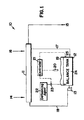
- Figure 1 is a block diagram of a schematic foam detection and control apparatus that uses thermal infrared emission to measure the temperature of a foam.
- the foam temperature is compared to the temperature of the aqueous medium to control addition of a foam control or defoaming agent.
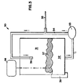
- Figure 3 is a sketch of a foam generating apparatus used to generate the data in Figure 2.
- Figure 5 is a graph showing effective control of foam using about 800 ppm of a silica/silicone/nonionic wetting agent combination defoaming material.
- Foam control agents or defoamers use foam characteristics to reduce foam.
- Foam is a non-equilibrium dispersion of gas bubbles or vapor in a relatively smaller volume of liquid.
- the gas content of a foam is greater than the volume of liquid required to produce the foam volume.
- An essential ingredient, in the liquid-based foam is materials that are dissolved or suspended in the liquid medium that have surface active, pseudo-surfactant or other surface properties that tend to support or promote foam generation. Such materials reside at the interface between gas and foam and are responsible for the tendency of the liquid foam and the stability of the resulting dispersion of bubbles.
- foam has certain desirable properties, unwanted generation of foam is a common problem affecting the efficiency and speed of a vast number of industrial processes involving mixing or agitating of multicomponent liquids. In all cases, control of foam rheology and stability is desired. These physical properties, in turn, are determined by both the physical chemistry of the liquid-gas or vapor interface and by the structure formed from the collection of gas bubbles. Foam made from a clear liquid often appears to be homogeneous and white. The foam often takes the color of the liquid medium. When observed more closely, however, foam has an intricate structure formed by the close packing of distinct gas or vapor bubbles. Foams often have a common distribution of large polyhedron bubbles in the top of a foam mass with smaller spherical bubbles at the bottom.
- Average bubble size is often around 1 to 2 millimeters depending upon aqueous composition and foam age. Liquid tends to drain from the top of a foam mass to the bottom resulting in the different bubble sizes and liquid concentration. Further, the bottom of a foam mass tends to be generally more wet, i.e., has greater amounts of aqueous liquid per volume of gas.
- non-equilibrium state of foam we mean that the foam generally tends to have a uniform bubble shape and size when generated, but after aging, the foam size and type tend to change to the common larger drier top structure with a smaller wetter bottom foam structure.
- the stability and rheology of a foam are closely inter-related with chemical composition and physical structure.
- the physical chemistry of the liquid-vapor interface in a modification by materials dissolved or suspended in the aqueous liquid plays a primary role in foam generation.
- Foaming is a surface phenomenon, anything that effects the surface causing foam can be considered a foaming surfactant.
- the interaction of defoaming processes and defoaming treatments at the foam aqueous liquid vapor interaction are critical. In foam production or reduction the behavior of individual molecules in solution and near a vapor liquid interface and the influence of these materials on interfacial forces is considered critical.
- the chemical constituents most commonly responsible for foaming are surfactants, i.e., surface active agents and other materials that tend to have a more hydrophilic portion of the molecule and a more hydrophobic portion of the molecule.
- surfactants i.e., surface active agents and other materials that tend to have a more hydrophilic portion of the molecule and a more hydrophobic portion of the molecule.
- the critical micelle concentration for the specific material, the molecules can align and promote foam formation.
- a large number of molecules in addition to synthetic surfactants can cause foaming.
- protein and peptide residues can contain relatively hydrophobic and relatively hydrophilic regions. Their presence suspended or dissolved in aqueous solutions can be foam producing.
- a large number of other components can also cause foaming including natural polysaccharide or cellulosic materials, natural fats such as phospholipids, partial esters of glycerol and a fatty acid, fatty acid molecules, and a large variety of other materials that can be derived from natural sources.
- Foams can be reduced in volume using three commonly understood mechanisms. Foams comprise liquid and vapor components that have different densities.
- the liquid material can drain from a liquid vapor interface region resulting in a thinner bubble wall.
- the fluid in the foam mass tends to drain by gravitational force to the bottom of the foam mass, typically the interface between the aqueous medium and the foam volume.
- the drainage proceeds until there is a vertical, hydrostatic pressure gradient that offsets the effective gravity on the liquid phase.
- Such drainage can increase the effect of defoaming processes or defoaming treatments since foam stability tends to be reduced in foams with reduced liquid content.
- Foam mass can also be reduced through film rupture. Foams evolve through the coalescents of neighboring bubbles via film rupture. Such rupture occurs if the nature of the surface active components or other materials dissolved or suspended in the liquid is such that the repulsive interactions and flow are not sufficient to keep neighboring bubbles apart. Bubble coalescents can increase as the liquid part of the foam drains and as reduced liquid content reduces the ability of the liquid to separate neighboring bubbles. Rupture can be increased by reducing the impact of surface active agents and other materials dissolved or suspended in the aqueous liquid by ensuring that the surface active agents cannot provide a sufficiently large barrier between bubbles. As the barrier is reduced by the effect of the foam, antifoam process or the defoaming treatment, bubble rupture then becomes more common.
- foams can continue to be thermal dynamically not in equilibrium because the gas inside foam bubbles can diffuse resulting in foam destruction. However, for most applications gas diffusion is a negligible component in foam stability.
- defoamers are also used to improve filtration, dewatering, washing and drainage of suspensions, mixtures or slurries. Examples of industrial operations that benefit from defoaming include oil well pumping, gas scrubbing at petro chemical plants, polymer and chemical synthesis and processing, textile dyeing and finishing, leather processing, paint and adhesive manufacture.
- Control of foam in aqueous media is used in a variety of chemical processing including aqueous media containing surfactant materials, crop residue, peptide residue, and any other material having surface active properties that can cause aqueous foam generation, control of waste water and sewage, food preparation, etc. is common.
- Most commonly available commercial defoamers are formulated specialty chemicals.
- a number of the specially formulated defoaming materials are discussed in J.C. Colberg, Foam and Emulsion Control Agents and Processes: Recent Developments, Noise Delta Corp., Parkridge, New Jersey (1981); and H. D. Kerner, Foam Control Agents, Noise Data Corp., Parkridge, New Jersey (1976).
- Other useful reviews of defoaming materials are those shown in R.
- Active ingredients in defoaming agents include liquid phase components comprising hydrocarbon defoamers, polyether defoamers, silica defoamers, silicone defoamers and fluorocarbon defoamers.
- hydrocarbon defoamers include kerosene and other paraffinic and naphthinic mineral oils, vegetable oils, oil derivatives such as ethoxylated rosin oil are known.
- Hydrocarbon defoamers also include organic polymers such as polyisobutylene, polyalkylene oxide, polyether, polyamines and others.
- the polyether group typically includes poly(alkylene oxide) homopolymers and copolymers. Both heteric and block copolymers comprising repeating portions derived from ethylene oxide and/or propylene oxide can be used to reduce foam in aqueous mixtures.
- high molecular weight adducts of propylene oxide with polyhydric alcohol such as ethylene glycol, glycerol, pentaerythritol, etc. can be useful.
- Silicone oils are known to be particularly effective in antifoaming activity.
- Polydimethylsiloxane is widely used in products for defoaming where thermal stability is important.
- fluorocarbon materials are expensive but effective antifoaming fluids.
- Fluorocarbon oils and fluorine containing amides such as N-(alkylaminotrimethylene) perfluoro octanamides are useful antifoaming additives.
- a number of antifoaming additives can cross lines between these identified classes such as fluorosilicones including polytrifluoropropylmethyl siloxanes and other fluorosilicones.
- the defoaming action of many active defoaming agents are enhanced through an interaction between the typically liquid defoaming composition and a solid particulate.
- polydimethylsiloxane is effective but has enhanced foam inhibiting activity in aqueous surfactant solutions when compounded with a hydrophobic silicon material.
- Three solid phase component classes are known hydrocarbon solids, silicone solids and fluorocarbon solids.
- Such defoamers can also contain ancillary agents that can maintain or improve defoaming activity.
- defoaming agents often comprise liquid and solid components, the defoaming agent can often require an emulsifier to maintain a single phase defoaming composition.
- defoaming compositions can be incorporated with carrier materials to produce an easily handleable, readily dispersible system for delivering the active defoaming components to the foaming system.
- a preferred defoamer comprises a mixture of a hydrophobic silica, a silicone and a nonionic wetting or compatibilizing agent.
- the defoamer acts to reduce foaming by enhancing the instability of the foam by increasing drainage effects, increasing gas diffusion between bubbles, reducing surface elasticity and by destabilizing other thin film effects.
- the amounts of the defoaming composition to be added to a foaming aqueous system is often empirically determined. Experiments are conducted with the defoamer composition and required defoaming concentrations in the aqueous media are determined simply by adding the defoamer in increasing amounts until the degree of required defoaming is obtained. In some processes little or no foaming can be tolerated. However, in most processes some amount of defoaming can be tolerated.
- a defoamer in an amount of about 50 to 2500 parts by weight of the defoamer composition per million parts by weight of the aqueous solution, preferably about 100 to 2000 or 200 to 1500 parts by weight per million parts by weight of the aqueous solution can be used initially. Such amounts can be adjusted after experience with a defoaming system is accumulated.
- the aqueous medium can contain a variety of components derived from agricultural processes associated with the fruits or vegetables.
- the materials include insecticides, herbicides, fertilizers, organic and inorganic vegetable/fruit matter, etc.
- One common material is an anti-microbial used to reduce the growth or numbers of microbs that can grow on the plant matter or in the aqueous medium.
- antimicrobials include active halogen materials, small molecule compounds, ozone, peroxy compounds, peracetic compounds, hydrogen peroxide, etc.
- the amount or volume of foam, or degree of defoaming is monitored using an infrared sensor or detector.
- infrared detectors fall into two classes, thermal and quantum (or photon) detectors.
- a thermal detector has a blackened surface that absorbs incident radiation at all wavelengths in which radiation manifests itself as heat. The resulting temperature change in the sensor element produces the detector signal.
- quantum detectors the infrared absorption excites the electrons, altering an electrical property of the detector, which is measured (photodetector properties).
- Thermal detectors have sensitivities that are independent of wavelength but are slow because the temperature change must occur. Quantum detectors are generally faster and more sensitive, but have a sensitivity that rises smoothly with increasing wavelength up to a long wavelength limit beyond which sensitivity drops rapidly.
- Infrared detectors are typically engineered for a particular temperature range.
- infrared detectors for high temperature processing such as manufacture of steel or other molten metals, can operate at a very high temperature range (1093,3-1648,9°C 2000-3000°F).
- Infrared sensors for use in this application are relatively low temperature infrared sensors that can detect the temperature of aqueous mediums typically below the boiling point of water (100°C).
- the preferred infrared sensors of the invention are sensors that detect common aqueous temperatures and are adapted to the acquisition of temperature data using modern computer or data processing techniques. Such infrared sensors can generate a signal that can be introduced into a computer through a conversion module.
- Such computers can be common lap top or desk top type computer systems.
- the infrared sensor can be mounted at any convenient location with respect to the aqueous medium at a site where foam accumulation is representative of foam generation in the aqueous system. Some empirical testing is required for optimal infrared sensor location.
- the sensor can be placed in a housing if necessary ensuring that the infrared transmission of the housing blocks no important quantity of infrared radiation. Commonly, the infrared sensor is positioned at a location above the aqueous medium such that the sensor remains above the level of any foam layer generated. Commonly, foam layers generated are less than 508 cm (200 inches), commonly less than 254 cm (100 inches) and often less than 152,4 cm (60 inches) in depth.
- the 0.7 to 14 ⁇ m (micron) band is commonly used for infrared measurement for convenience purposes, however, sensors can be engineered to detect infrared radiation throughout the infrared band.
- the temperature of a material is typically the source of infrared energy emitted by the object.
- the energy emitted by an object can be measured by infrared thermometer.
- Such a thermometer typically can be contacted by infrared energy that is obtained from the ambient environment, emitted from the system or transmitted through the system.
- An infrared sensor should be mounted in such a location such that the emitted energy of the system is measured. Adjustments to the thermometer can be made to remove the interference from the environment.
- the Raytek® Thermalert non-contact temperature sensors for process monitoring and control are preferred infrared sensing devices.
- the selection of an infrared sensor that has an appropriate focus on the foam generating site can be selected by one of ordinary skill in the art.
- the temperature of the aqueous medium can be determined using the infrared sensors of the invention or any other temperature generating measurement. Thermocouples, thermistors, bimetal strips, mercury thermometers, alcohol thermometers, etc. can all be used to measure the temperature of the aqueous medium. Such a temperature can be used in comparison to the infrared emission temperature of the foam for control of the addition of the foam control agent.
- the temperature of the aqueous medium can be read manually by the operator or can be measured electronically using a thermistor or thermocouple and such data can then be acquired by the computer/controller for comparison to the temperature of the foam layer. Such a measurement can be taken at any convenient place for measurement of the aqueous medium.
- the aqueous medium temperature can be measured in the process unit, an accumulation zone, a treatment zone, or in any line or pump convenient for measurement.
- the temperature of the aqueous medium can be controlled using common control equipment and that set point can be used as a program set point in the computer controller. In such an instance, a continuous measurement of the temperature is not required.
- the set point comprising the measurement required for addition of foam control agent.
- a control system to compare the temperature of the aqueous medium to the infrared emission of the foam layer generated on the aqueous medium can be used.
- Such a control system can comprise an operator comparing temperatures generated by the system.
- an automatic microprocessor-based control system is preferred such as those made by Chromalox® .
- Automatic control systems for dosing aqueous media with appropriate chemicals have been used for many years.
- Such control systems can be programmed with a predetermined temperature difference limit. When this temperature difference limit is exceeded, the system can cause the addition of the foam control agent into the aqueous medium.
- the amount of foam control agent can be pulsed into the aqueous medium or can be added continually until foam control is achieved.
- a constant amount of the foam control agent is pumped into the aqueous medium in a duty cycle such that during a ten minute cycle, (e.g.) the pulse will occur cyclically at every minute until foam control is achieved.
- Other duty cycles can be used such that during a one minute cycle, the pulse can have a ten, twenty, thirty or fifty second cycle. The cycle is repeated until foam control is achieved.
- the control system can add the defoamer material continually until foaming is controlled.
- a concentration of defoamer is achieved that ranges from about 50 to about 2500 ppm of defoaming agent in the aqueous medium, preferably about 100 to about 1000 ppm of foam control agent in the aqueous medium.
- a variety of commercial control systems are available and can be selected by one of ordinary skill in the art.
- Figure 1 shows a block diagram or a schematic of the infrared foam detection and control process and apparatus of the invention.
- a foam system and foam controller apparatus 10 comprising a flume 11 and an aqueous medium 24 in a treatment tank 12 for the addition of a defoaming agent to the aqueous medium.
- a flume is an device using a mobile stream of an aqueous liquid to transport a product stream such as agricultural produce from an unloading station into and through a processing plant.
- the foam control tank 12 contains the aqueous medium 24 that is moved through the flume 11 using pump 13. In the operation of the flume, aqueous medium from the tank 12 passes through pump 13 into the flume 11.
- the water in flume 11 and the tank 12 can generate substantial quantities of foam as a result of foreign matter, dirt, agricultural residue, antimicrobial materials, fertilizer, insecticide, fruit or vegetable matter and any other material arising in the agricultural location. Such material becomes dissolved or suspended in the flume liquid and requires foam control.
- the flume is maintained with an adequate supply of water by supplying make up water at make up inlet 16.
- the flume generally contains sufficient water to transport efficiently produce from truck or primary flume port 14 to processing port 15.
- the temperature of the aqueous medium, contained in the flume 11 or in the tank 12 or in any line 17 or 18 carrying aqueous medium in the process can be measured.
- the temperature of the medium 24 in tank 12 is measured using thermocouple or thermistor 25.
- any foam generated from the aqueous medium in any portion of the process equipment can be measured to control foam.
- Figure 1 shows a temperature measurement of foam 19 in tank 12 using a thermal infrared detector 20. We have found that the foam layer has an apparent temperature typically substantially less than the temperature of the aqueous medium.
- the infrared detector 20, or a series of detectors measures the temperature of the foam layer 19 if any and compares the temperature of the foam layer 19 to the temperature, as measured by thermistor or thermocouple 25, of the aqueous medium 24 in the tank 12.
- An electronic controller 21 compares the temperature of the foam layer 19 to the temperature of the aqueous medium 24 in the tank 12 and if that temperature is greater than a predetermined limit, the controller causes a source of defoaming agent 22, using a pump 23, to introduce an effective foam controlling concentration of the defoaming agent in the aqueous medium in tank 12.
- the foam control agent can be added to the aqueous medium at any point in the process stream, however, it is more convenient to add the foam control agent close to the IR sensor 20 that detects the foaming characteristics of the aqueous medium in the tank 12.
- This experiment utilized a heat detecting IR gun placed over a circulating aqueous potato effluent stream which generated a foam by mechanical circulation.
- the potato effluent had been obtained from a commercial potato processing plant.
- the data demonstrates the insulating effect, at various temperatures, for various foam heights generated in an aqueous transport system pumping potato water.
- Figure 3 shows the apparatus 30 used in generating the data shown in Figure 2.
- Figure 3 shows apparatus 30 comprising a holding chamber 31 containing about 3 liters of potato effluent 32.
- the potato effluent 32 is pumped using pump 33 through line 34 containing a column thermometer 35.
- the potato effluent is returned to the chamber 31 through outlet 36.
- a foam layer 37 is generated by the mechanical pumping and transfer of the potato effluent.
- An infrared detector 38 is installed in the holding chamber to detect the temperature of the foam layer 37.
- the effluent 32 can be heated or cooled using temperature control means 39.
- a commercial potato effluent defoamer was manually added to the commercial potato effluent.
- the defoamer used was GWPD-655 defoamer, which is a silica/silicone/nonionic mixture used at a concentration of about 500-1,000 ppm.
- the data shows that at about 21,1°C (70°F), there is a significant, greater than about 1,11°C (2°F) temperature difference, between the aqueous medium effluent and an approximately 2 centimeter foam layer. Below 21,1°C (70°F), some difference is shown even with thick foam heights. However, depending on food source, soil concentration and other aqueous components, the differences in temperature between the aqueous medium and the foam may not be sufficient to be used as a control indicator. However, at temperatures greater than about 21,1°C (70°F), the magnitude of difference in temperature between the foam and the aqueous medium is sufficient for control purposes.
- the transport flumes containing a defoamer composition were operated and a condition of freedom from substantial foam was attained.
- the temperature of the various flume effluents were measured, then the addition of a defoamer material was interrupted in order to generate foam.
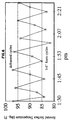
- Figure 4 shows data for three aqueous flumes including a potato peeler flume, a potato cutter flume and a potato inspection flume.
- the vertical dimension is temperature and the horizontal dimension is time.
- the data shows that for all three flumes, with a low level of foam (shown in Figure 4 as less than 2,54 cm (one inch) labile foam that is dynamically formed and broken, and thus acceptable for pump operation) that little heat difference is recorded when compared to the potato water (defoamed condition).
- the thin dynamic foam has little thermal insulating effect and does not trigger the addition of defoaming materials.
- the foam began to change in stability and character.
- a stable relatively dense foam layer began to foam shown as a 2,54-7,62 cm (1-3 inch) stable foam.
- this data shows a thermal insulating effect of about 2,78-6,11°C (5-11°F) difference between the foam and the aqueous medium was found. While this level of foam did not prevent the proper operation of the flume, we consider this level of foam to be sufficient to begin defoaming to ensure that no improper operation of the pumps or other aspects of the flume occurred. Without addition of defoamer, a considerable level of stable foam was formed in each of the flumes designated as a 7,62 cm (3+ inch) stable foam. An increased temperature difference between the aqueous medium (potato water) and the stable foam was noted (quantitatively about 7,78-12,78°C (14-23°F)).
- Figure 5 shows an experiment using two defoaming materials in defoaming potato peeler water in a commercial facility.
- Figure 5 shows the reduction in foam height resulting from the use of varying concentration of one of two defoamer materials. The curves show that as the defoaming material is added to the peeler water, the foam height is decreased to less than one inch at 400 ppm defoamer. The foam height reaches a constant height of about 0,64 cm (0.25 inch) at 800 ppm defoamer.
- a multiple set of foam/defoam cycles were performed to simulate a commercial foam control system.
- An infrared emission recorder was placed 2,44 m (8 feet) over the flume (foam layer) surface and the surface temperature was recorded.
- the flume foam was totally removed using the addition of about 800 parts of an aqueous defoamer composition (GWPD-655) per million parts of the flume water and the temperature was read after defoaming.
- GWPD-655 aqueous defoamer composition
- the defoamed aqueous medium had a surface temperature or emission of about 34,4-36,1°C (94-97°F).
- the foam was permitted to accumulate to produce a foaming layer about 7,62-15,24 cm (3-6 inches) in depth.
- the apparent temperature of the surface of the aqueous medium insulated by the foam substantially dropped greater than 5,56°C (10°F).
- the temperature changes from about 35,6°C (96°F) to about 28,89°C (84°F) producing a surface difference of about 4,44-8,33°C (8-15°F) difference.
- the foam was reduced in an intermediate step and totally defoamed as shown on the graphs. These cycles were repeated in a series of cycles to show the use of an infrared sensor to control defoamer composition addition and foam control.
- the figure shows that in foams generated in a warewashing machine having a foam that derives from milk and surfactant cleaning residues, relatively thin film layers can cause significant differences in measurement of temperature between bulk liquid and foam surface.
- the results of the experiment demonstrate that a foaming cycle where low levels of defoamed egg foam 0,25 cm (0.1 inch) have relatively low thermal difference (bulk solution phase versus IR emission from foam) while greater levels of added egg foam (rated as then 0,32 cm (0.125 inch) yield substantially increased temperature differences 3,89-13,89°C (7-25°F) when comparing the bulk aqueous liquid to the foam layer.
- the defoaming efficiency of the process of this invention and of comparative compositions was determined in a Glewwe Foam meter which provides a dynamic foam test rather than a static test (as in the case of the Ross-Miles foam test).
- a dynamic foam meter is considered more appropriate for simulation of industrial conditions, e.g. the conditions in a flume.
- the equipment and general procedure for the Glewwe form test is described in U.S. Pat. No. 3,899,387, column 12, line 45 et seq.
- the foam meter itself consists of a thermostated reservoir and a pump to recirculate the aqueous medium with foaming tendencies. The foam developed by the action of the aqueous stream impinging on the surface in the reservoir causes foam formation.
- the foam height is measured after various time intervals and provides a relative measure of the effectiveness of the defoamer added to the black liquor.
- 3,000 ml of the medium was used.
- the reservoir of this foam meter consists of a stainless steel laboratory beaker of 3,000 ml capacity. Sealed to this beaker by means of a silicone sealant is a clear Plexiglass tubing which snugly fits into the inner walls of the beaker. This enables the operator to measure the foam height above the liquor level.
- the beaker measures about 19 cm high by about 17 to 18 cm in diameter and the Plexiglass tube extends about 30 to 35 cm above the lip of this beaker. Detail regarding the Glewwe foam test is shown in Steindorf, U.S. Patent No. 5,447,648.
Landscapes
- Chemical & Material Sciences (AREA)
- Health & Medical Sciences (AREA)
- Toxicology (AREA)
- Dispersion Chemistry (AREA)
- Chemical Kinetics & Catalysis (AREA)
- Degasification And Air Bubble Elimination (AREA)
- Removal Of Floating Material (AREA)
- Radiation Pyrometers (AREA)
Claims (21)
- Verfahren zum Einstellen eines Schaums in einem wässrigen Medium, in dem eine Schäumung durchgeführt wird, wobei das Medium in einem System enthalten ist und das Verfahren folgende Schritte umfasst:(a) Messen der thermischen Infrarot-Emission eines Schaums, der aus dem wässrigen Medium abgeleitet wird;(b) Vergleichen einer Temperatur des wässrigen Mediums mit einer Temperatur, die abgeleitet ist aus der Messung der thermischen Infrarot-Emission des Schaums; und(c) Entschäumen des wässrigen Mediums wenn der Unterschied zwischen der Temperatur des wässrigen Mediums und der Temperatur des Schaums größer ist als ein vorgegebener Grenzwert.
- Verfahren nach Anspruch 1, bei dem das Entschäumen des wässrigen Mediums durchgeführt wird mittels einer Wasser-Behandlung, die in dem wässrigen Medium eine wirksame Konzentration eines Schaum-Einstellmittels erzeugt.
- Verfahren nach Anspruch 1, bei dem das Entschäumen des wässrigen Mediums erreicht wird unter Verwendung eines Entschäumverfahrens.
- Verfahren nach Anspruch 1, bei dem die Temperatur des wässrigen Mediums bestimmt wird durch eine Messung der thermischen Infrarot-Emission des wässrigen Mediums.
- Verfahren nach Anspruch 1, bei dem die Temperatur des wässrigen Mediums bestimmt wird durch Verwendung einer konstanten, vorgegebenen Temperatur, die durch das System gesetzt wird.
- Verfahren nach Anspruch 1, wobei der vorgegebene Grenzwert größer ist als 1,11°C (2°F) und wobei die wirksame Konzentration des Schaumeinstellmittels etwa bei 50 bis 2.500 Gewichtsteilen des Mittels pro 1 Million Gewichtsteile des Mediums beträgt.
- Verfahren nach Anspruch 1, wobei der vorgegebene Grenzwert größer ist als 2,78°C (5°F) und wobei die wirksame Konzentration des Schaumeinstellmittels bei etwa 50 bis 2.000 Gewichtsteilen des Mittels pro 1 Million Gewichtsteilen des Mediums beträgt.
- Verfahren nach Anspruch 1, wobei die Infrarot-Emission mit einem thermischen IR Detektor gemessen wird.
- Verfahren nach Anspruch 1, wobei das wässrige Medium auf einem konstanten Temperatur-Sollwert gehalten wird und wobei der Temperatur-Sollwert gewählt wird als Maß der Temperatur des Mediums.
- Verfahren nach Anspruch 1, wobei ein Teil des wässrigen Mediums mechanisch schaumfrei gehalten wird, um seine Temperatur zu messen unter Verwendung der thermischen Infrarot-Emission des wässrigen Mediums.
- Verfahren nach Anspruch 1, wobei die Temperatur des wässrigen Mediums mit einem Thermometer oder einem Thermistor gemessen wird, und wobei diese Temperatur verwendet wird, um ein Maß für die Temperatur des wässrigen Mediums zu erzeugen.
- Verfahren nach Anspruch 1, wobei das wässrige Medium ein landwirtschaftliches Produkt und eine antimikrobielle zusammensetzung enthält.
- Verfahren nach Anspruch 1, wobei die Temperatur des wässrigen Mediums erhalten wird durch Messung der Infrarot-Emission des wässrigen Mediums.
- Verfahren nach Anspruch 1, wobei die Differenz zwischen der Temperatur des wässrigen Mediums und der Temperatur des Schaums größer ist als 1,11°C (2°F) und die wirksame Konzentration des Schaumeinstellmittels bei etwa 50 bis 2.500 Gewichtsteilen des Schaumeinstellmittels pro 1 Million Gewichtsteile des wässrigen Mediums beträgt.
- Verfahren nach Anspruch 1, wobei die Differenz zwischen der Temperatur des wässrigen Mediums und der Temperatur des Schaums größer ist als 2,78°C (5°F) und die wirksame Konzentration des Schaumeinstellmittels bei etwa 100 bis 2.000 Gewichtsteilen Schaumeinstellmittel pro 1 Million Gewichtsteile des wässrigen Mediums beträgt.
- Verfahren nach Anspruch 1, wobei das wässrige Medium eine mobile wässrige Phase in einer Schwemmrille aufweist.
- Verfahren nach Anspruch 12, wobei das landwirtschaftliche Produkt ein frisch geerntetes Gemüse enthält.
- Verfahren nach Anspruch 12, wobei die antimikrobielle Zusammensetzung eine antimikrobielle Peroxy-Verbindung enthält.
- Verfahren nach Anspruch 1, wobei die antimikrobielle Zusammensetzung eine Peressigsäure oder eine WasserstoffPeroxid-Zusammensetzung enthält.
- Verfahren nach Anspruch 1, wobei die Temperatur bestimmt wird unter Verwendung eines Quecksilber- oder Alkohol-Säulenthermometers.
- Verfahren nach Anspruch 1, wobei die Temperatur bestimmt wird unter Verwendung eines Eichthermometers, das durch ein Thermoelement gespeist wird.
Applications Claiming Priority (3)
| Application Number | Priority Date | Filing Date | Title |
|---|---|---|---|
| US08/729,140 US5868859A (en) | 1996-10-11 | 1996-10-11 | Use of infrared radiation in detection methods to defoam aqueous systems |
| PCT/US1997/014569 WO1998016290A1 (en) | 1996-10-11 | 1997-08-20 | The use of infrared radiation in detection methods to defoam aqueous systems |
| US729140 | 2000-12-01 |
Publications (2)
| Publication Number | Publication Date |
|---|---|
| EP0946239A1 EP0946239A1 (de) | 1999-10-06 |
| EP0946239B1 true EP0946239B1 (de) | 2002-02-13 |
Family
ID=24929755
Family Applications (1)
| Application Number | Title | Priority Date | Filing Date |
|---|---|---|---|
| EP97938421A Expired - Lifetime EP0946239B1 (de) | 1996-10-11 | 1997-08-20 | Verwendung von infrarot strahlung für detektions methoden beim entschäumen wässriger systeme |
Country Status (10)
| Country | Link |
|---|---|
| US (1) | US5868859A (de) |
| EP (1) | EP0946239B1 (de) |
| JP (1) | JP2001502231A (de) |
| AR (1) | AR009965A1 (de) |
| AU (1) | AU4074697A (de) |
| CA (1) | CA2268081C (de) |
| DE (1) | DE69710489T2 (de) |
| MX (1) | MXPA99003370A (de) |
| WO (1) | WO1998016290A1 (de) |
| ZA (1) | ZA977953B (de) |
Families Citing this family (13)
| Publication number | Priority date | Publication date | Assignee | Title |
|---|---|---|---|---|
| US6435710B1 (en) * | 1998-08-26 | 2002-08-20 | Fauske & Associates, Inc. | Foam detector apparatus and method |
| US6461414B1 (en) | 1999-10-29 | 2002-10-08 | Baker Hughes Incorporated | Foam monitoring and control system |
| US6748793B2 (en) | 2001-12-28 | 2004-06-15 | E. I. Du Pont De Nemours And Company | Ultrasound sensing of concentration of methanol's aqueous solution |
| US6815682B2 (en) * | 2001-12-28 | 2004-11-09 | E. I. Du Pont De Nemours And Company | Infrared sensing of concentration of methanol's aqueous solution |
| WO2005098377A1 (en) * | 2004-03-16 | 2005-10-20 | Tribo Flow Separations, Llc | Instruments, related systems, and methods for monitoring or controlling foaming |
| US7988792B2 (en) * | 2005-05-13 | 2011-08-02 | Cm Quantum Technologies, Llc | Automatic egg washing apparatus |
| WO2011145083A2 (en) | 2010-05-20 | 2011-11-24 | Ecolab Usa Inc. | Rheology modified low foaming liquid antimicrobial compositions and methods of use thereof |
| US10271679B2 (en) * | 2013-04-10 | 2019-04-30 | William Westmore Purton | Espresso milk frother |
| AU2017268138A1 (en) * | 2016-05-17 | 2018-12-06 | Solenis Technologies, L.P. | Side-stream foam monitor and control system |
| EP3884072A4 (de) * | 2018-11-21 | 2022-08-17 | Buckman Laboratories International, Inc. | Wirksame schaumkontrolle bei prozesswasser zum waschen von rüben durch automatische anwendung eines entschäumers |
| US12184828B2 (en) | 2022-10-07 | 2024-12-31 | Global Life Sciences Solutions Usa Llc | Apparatus, system and method for foam detection utilizing stereo imaging |
| CN115656049B (zh) * | 2022-11-17 | 2025-03-21 | 太原理工大学 | 一种自动化泡沫性能检测装置及工作方法 |
| CN118403826B (zh) * | 2024-06-28 | 2024-10-29 | 山东中禾电缆科技有限公司 | 一种电缆清洁装置 |
Citations (1)
| Publication number | Priority date | Publication date | Assignee | Title |
|---|---|---|---|---|
| US5437842A (en) * | 1991-03-28 | 1995-08-01 | J. R. Simplot Company | Foam control system |
Family Cites Families (19)
| Publication number | Priority date | Publication date | Assignee | Title |
|---|---|---|---|---|
| JPS51122671A (en) * | 1975-04-19 | 1976-10-26 | Nippon Atom Ind Group Co Ltd | A method of inhibiting foaming in evaporators,etc. |
| US4392782A (en) * | 1980-11-13 | 1983-07-12 | Comact Pump Corporation | Liquid level controller |
| GB2146253A (en) * | 1983-09-12 | 1985-04-17 | Haden Drysys Int Ltd | A separation system including a flotation tank having level control means |
| US5026989A (en) * | 1985-10-07 | 1991-06-25 | Nordson Corporation | System for monitoring material dispensed onto a substrate |
| US4756670A (en) * | 1986-10-17 | 1988-07-12 | Andros Analyzers Incorporated | Detecting method and apparatus using heat sensitive devices |
| DE3737607A1 (de) * | 1987-11-05 | 1989-05-24 | Hoefelmayr Bio Melktech | Verfahren und vorrichtung zur durchfuehrung von messungen an einer schaeumenden fluessigkeit |
| DE8904504U1 (de) * | 1989-04-11 | 1989-05-18 | FAG Kugelfischer Georg Schäfer KGaA, 8720 Schweinfurt | Dichtung für Pendellager |
| US5167243A (en) * | 1991-02-28 | 1992-12-01 | Lorillard Tobacco Company | Disinfestation system for agricultural products |
| JP2641333B2 (ja) * | 1991-03-13 | 1997-08-13 | 日本碍子株式会社 | 熱式流量センサ |
| US5397028A (en) * | 1992-04-29 | 1995-03-14 | Jesadanont; Mongkol | Automatic fluid dispenser and method |
| US5273060A (en) * | 1992-06-26 | 1993-12-28 | Martin Marietta Corporation | Alcohol spray cleaning system |
| JPH07114955B2 (ja) * | 1992-08-31 | 1995-12-13 | 三洋化成工業株式会社 | 反応物横溢防止方法 |
| US5305915A (en) * | 1992-09-18 | 1994-04-26 | Sloan Valve Company | Liquid dispensing pump with splash minimizing adjustment and volume dispensing adjustment |
| US5263112A (en) * | 1992-11-02 | 1993-11-16 | The United States Of America As Represented By The Secretary Of The Army | Infrared fiber optic distribution sensor |
| US5409713A (en) * | 1993-03-17 | 1995-04-25 | Ecolab Inc. | Process for inhibition of microbial growth in aqueous transport streams |
| AU671746B2 (en) * | 1993-05-28 | 1996-09-05 | Ecolab Inc. | Low product alarm for solid products |
| US5390541A (en) * | 1993-10-12 | 1995-02-21 | Feller; Murray F. | Flow sensor incorporating cyclic relative motion between fluid flow and detecting element |
| JPH07114955A (ja) * | 1993-10-19 | 1995-05-02 | Fuji Electric Co Ltd | 電子装置のコネクタの固定構造 |
| US5446516A (en) * | 1994-02-23 | 1995-08-29 | Fischer Industries, Inc. | Replenisher system for x-ray film processor |
-
1996
- 1996-10-11 US US08/729,140 patent/US5868859A/en not_active Expired - Lifetime
-
1997
- 1997-08-20 AU AU40746/97A patent/AU4074697A/en not_active Abandoned
- 1997-08-20 WO PCT/US1997/014569 patent/WO1998016290A1/en not_active Ceased
- 1997-08-20 EP EP97938421A patent/EP0946239B1/de not_active Expired - Lifetime
- 1997-08-20 JP JP10518322A patent/JP2001502231A/ja active Pending
- 1997-08-20 DE DE69710489T patent/DE69710489T2/de not_active Expired - Lifetime
- 1997-08-20 CA CA002268081A patent/CA2268081C/en not_active Expired - Lifetime
- 1997-08-20 MX MXPA99003370A patent/MXPA99003370A/es active IP Right Grant
- 1997-09-04 ZA ZA977953A patent/ZA977953B/xx unknown
- 1997-10-10 AR ARP970104686A patent/AR009965A1/es unknown
Patent Citations (1)
| Publication number | Priority date | Publication date | Assignee | Title |
|---|---|---|---|---|
| US5437842A (en) * | 1991-03-28 | 1995-08-01 | J. R. Simplot Company | Foam control system |
Also Published As
| Publication number | Publication date |
|---|---|
| US5868859A (en) | 1999-02-09 |
| EP0946239A1 (de) | 1999-10-06 |
| MXPA99003370A (es) | 2004-09-07 |
| DE69710489D1 (de) | 2002-03-21 |
| WO1998016290A1 (en) | 1998-04-23 |
| AU4074697A (en) | 1998-05-11 |
| JP2001502231A (ja) | 2001-02-20 |
| DE69710489T2 (de) | 2002-10-10 |
| AR009965A1 (es) | 2000-05-17 |
| ZA977953B (en) | 1999-03-04 |
| CA2268081A1 (en) | 1998-04-23 |
| CA2268081C (en) | 2006-07-04 |
Similar Documents
| Publication | Publication Date | Title |
|---|---|---|
| EP0946239B1 (de) | Verwendung von infrarot strahlung für detektions methoden beim entschäumen wässriger systeme | |
| EP0662367A1 (de) | CO2-Sprühstrahlsystem mit einem thermischen CO2-Schneestromanzeiger | |
| US7777868B2 (en) | System for measuring non-volatile residue in ultra pure water | |
| Ruzicka et al. | Effect of surfactant on homogeneous regime stability in bubble column | |
| Ferrari et al. | Adsorption kinetics of alkylphosphine oxides at water/hexane interface: 1. Pendant drop experiments | |
| Malysa et al. | Foams under dynamic conditions | |
| CN109564149B (zh) | 侧流泡沫监测与控制系统 | |
| Samanta et al. | Coalescence of bubbles and stability of foams in aqueous solutions of Tween surfactants | |
| Myrvold et al. | Surface elasticity and viscosity from oscillating bubbles measured by automatic axisymmetric drop shape analysis | |
| Carey et al. | Properties of aqueous foams stabilized by dodecyltrimethylammonium bromide | |
| Jha et al. | Silicone antifoam performance: correlation with spreading and surfactant monolayer packing | |
| Micale et al. | Assessment of particle suspension conditions in stirred vessels by means of pressure gauge technique | |
| Saien et al. | Improving performance of liquid–liquid extraction with temperature for mass transfer resistance in both phases | |
| Hreczuch et al. | 2‐Ethylhexanol derivatives as nonionic surfactants: synthesis and properties | |
| Thiele et al. | Experimental investigations of foaming in a packed tower for sour water stripping | |
| Sonobe et al. | Salting out effect on Triton X-405 layer at the octane-water interface during microwave heating | |
| US3926044A (en) | Closed-loop water-washable inspection penetrant process | |
| McGee | Selecting chemical defoamers and antifoams | |
| Hashem et al. | Drop formation mass transfer coefficients in extraction columns | |
| Bungay et al. | Handling of antifoam oils for fermentations | |
| Uchida et al. | Flow regimes and mass transfer in counter‐current bubble columns | |
| AU2006271753A1 (en) | Method for controlling foaming in a process | |
| US5799676A (en) | Nonaqueous solvent regenerating apparatus for use in cleaning | |
| Storozhenko et al. | A study of the defoaming properties of dry silicone compositions | |
| Nakache et al. | Determination of a coalescence parameter related to the stability of emulsions with polymeric surfactants |
Legal Events
| Date | Code | Title | Description |
|---|---|---|---|
| PUAI | Public reference made under article 153(3) epc to a published international application that has entered the european phase |
Free format text: ORIGINAL CODE: 0009012 |
|
| 17P | Request for examination filed |
Effective date: 19990409 |
|
| AK | Designated contracting states |
Kind code of ref document: A1 Designated state(s): BE DE ES FR GB IT NL |
|
| 17Q | First examination report despatched |
Effective date: 19991123 |
|
| GRAG | Despatch of communication of intention to grant |
Free format text: ORIGINAL CODE: EPIDOS AGRA |
|
| GRAG | Despatch of communication of intention to grant |
Free format text: ORIGINAL CODE: EPIDOS AGRA |
|
| GRAH | Despatch of communication of intention to grant a patent |
Free format text: ORIGINAL CODE: EPIDOS IGRA |
|
| GRAH | Despatch of communication of intention to grant a patent |
Free format text: ORIGINAL CODE: EPIDOS IGRA |
|
| GRAA | (expected) grant |
Free format text: ORIGINAL CODE: 0009210 |
|
| REG | Reference to a national code |
Ref country code: GB Ref legal event code: IF02 |
|
| AK | Designated contracting states |
Kind code of ref document: B1 Designated state(s): BE DE ES FR GB IT NL |
|
| PG25 | Lapsed in a contracting state [announced via postgrant information from national office to epo] |
Ref country code: IT Free format text: LAPSE BECAUSE OF FAILURE TO SUBMIT A TRANSLATION OF THE DESCRIPTION OR TO PAY THE FEE WITHIN THE PRE;WARNING: LAPSES OF ITALIAN PATENTS WITH EFFECTIVE DATE BEFORE 2007 MAY HAVE OCCURRED AT ANY TIME BEFORE 2007. THE CORRECT EFFECTIVE DATE MAY BE DIFFERENT FROM THE ONE RECORDED.SCRIBED TIME-LIMIT Effective date: 20020213 Ref country code: BE Free format text: LAPSE BECAUSE OF FAILURE TO SUBMIT A TRANSLATION OF THE DESCRIPTION OR TO PAY THE FEE WITHIN THE PRESCRIBED TIME-LIMIT Effective date: 20020213 |
|
| REF | Corresponds to: |
Ref document number: 69710489 Country of ref document: DE Date of ref document: 20020321 |
|
| ET | Fr: translation filed | ||
| PG25 | Lapsed in a contracting state [announced via postgrant information from national office to epo] |
Ref country code: ES Free format text: LAPSE BECAUSE OF FAILURE TO SUBMIT A TRANSLATION OF THE DESCRIPTION OR TO PAY THE FEE WITHIN THE PRESCRIBED TIME-LIMIT Effective date: 20020829 |
|
| PLBE | No opposition filed within time limit |
Free format text: ORIGINAL CODE: 0009261 |
|
| STAA | Information on the status of an ep patent application or granted ep patent |
Free format text: STATUS: NO OPPOSITION FILED WITHIN TIME LIMIT |
|
| 26N | No opposition filed |
Effective date: 20021114 |
|
| PGFP | Annual fee paid to national office [announced via postgrant information from national office to epo] |
Ref country code: DE Payment date: 20130814 Year of fee payment: 17 |
|
| PGFP | Annual fee paid to national office [announced via postgrant information from national office to epo] |
Ref country code: NL Payment date: 20140809 Year of fee payment: 18 |
|
| PGFP | Annual fee paid to national office [announced via postgrant information from national office to epo] |
Ref country code: FR Payment date: 20140808 Year of fee payment: 18 Ref country code: GB Payment date: 20140820 Year of fee payment: 18 |
|
| REG | Reference to a national code |
Ref country code: DE Ref legal event code: R119 Ref document number: 69710489 Country of ref document: DE |
|
| REG | Reference to a national code |
Ref country code: DE Ref legal event code: R119 Ref document number: 69710489 Country of ref document: DE Effective date: 20150303 |
|
| PG25 | Lapsed in a contracting state [announced via postgrant information from national office to epo] |
Ref country code: DE Free format text: LAPSE BECAUSE OF NON-PAYMENT OF DUE FEES Effective date: 20150303 |
|
| GBPC | Gb: european patent ceased through non-payment of renewal fee |
Effective date: 20150820 |
|
| REG | Reference to a national code |
Ref country code: NL Ref legal event code: MM Effective date: 20150901 |
|
| REG | Reference to a national code |
Ref country code: FR Ref legal event code: ST Effective date: 20160429 |
|
| PG25 | Lapsed in a contracting state [announced via postgrant information from national office to epo] |
Ref country code: NL Free format text: LAPSE BECAUSE OF NON-PAYMENT OF DUE FEES Effective date: 20150901 |
|
| PG25 | Lapsed in a contracting state [announced via postgrant information from national office to epo] |
Ref country code: GB Free format text: LAPSE BECAUSE OF NON-PAYMENT OF DUE FEES Effective date: 20150820 |
|
| PG25 | Lapsed in a contracting state [announced via postgrant information from national office to epo] |
Ref country code: FR Free format text: LAPSE BECAUSE OF NON-PAYMENT OF DUE FEES Effective date: 20150831 |