EP0945973A2 - Control device for a single phase synchronous motor - Google Patents
Control device for a single phase synchronous motor Download PDFInfo
- Publication number
- EP0945973A2 EP0945973A2 EP99105656A EP99105656A EP0945973A2 EP 0945973 A2 EP0945973 A2 EP 0945973A2 EP 99105656 A EP99105656 A EP 99105656A EP 99105656 A EP99105656 A EP 99105656A EP 0945973 A2 EP0945973 A2 EP 0945973A2
- Authority
- EP
- European Patent Office
- Prior art keywords
- voltage
- control electronics
- rotor
- stator winding
- switch
- Prior art date
- Legal status (The legal status is an assumption and is not a legal conclusion. Google has not performed a legal analysis and makes no representation as to the accuracy of the status listed.)
- Granted
Links
Images


Classifications
-
- H—ELECTRICITY
- H02—GENERATION; CONVERSION OR DISTRIBUTION OF ELECTRIC POWER
- H02P—CONTROL OR REGULATION OF ELECTRIC MOTORS, ELECTRIC GENERATORS OR DYNAMO-ELECTRIC CONVERTERS; CONTROLLING TRANSFORMERS, REACTORS OR CHOKE COILS
- H02P6/00—Arrangements for controlling synchronous motors or other dynamo-electric motors using electronic commutation dependent on the rotor position; Electronic commutators therefor
- H02P6/20—Arrangements for starting
- H02P6/22—Arrangements for starting in a selected direction of rotation
-
- H—ELECTRICITY
- H02—GENERATION; CONVERSION OR DISTRIBUTION OF ELECTRIC POWER
- H02P—CONTROL OR REGULATION OF ELECTRIC MOTORS, ELECTRIC GENERATORS OR DYNAMO-ELECTRIC CONVERTERS; CONTROLLING TRANSFORMERS, REACTORS OR CHOKE COILS
- H02P1/00—Arrangements for starting electric motors or dynamo-electric converters
- H02P1/16—Arrangements for starting electric motors or dynamo-electric converters for starting dynamo-electric motors or dynamo-electric converters
- H02P1/46—Arrangements for starting electric motors or dynamo-electric converters for starting dynamo-electric motors or dynamo-electric converters for starting an individual synchronous motor
- H02P1/465—Arrangements for starting electric motors or dynamo-electric converters for starting dynamo-electric motors or dynamo-electric converters for starting an individual synchronous motor for starting an individual single-phase synchronous motor
Definitions
- the invention relates to a device for controlling the Start-up and operation of a non-self-starting Single-phase synchronous motor, at least one of which Stator winding via one of control electronics controlled switch to the AC voltage of a network is switchable.
- Such a device is for starting one Single-phase synchronous motor necessary because of its comparatively high power, for example> 50 W, due to the design when applying the AC voltage to the network does not start by itself and that in a certain Direction of rotation should start.
- Such synchronous motors will be for example in household machines, especially for Water pumps for dishwashers used.
- a device of the type mentioned is from the EP 0 654 890 B1 known. There is to capture the a position sensor is required for the respective position of the rotor, which is, for example, a Hall sensor. Dependent on from the sensor signal and the respective polarity of the AC voltage, the switch (triac) is ignited when the current based on the switched AC voltage with the respective orientation of the magnetic field of the Rotors a torque in the direction of the desired one Direction of rotation results.
- a position sensor is in terms of structure and the assembly is complex. It must be integrated in the engine and be connected to the control electronics.
- EP 0 691 732 B1 describes an inverter for one Single-phase synchronous motor described, for example can be used for the pump drive in a dishwasher is.
- DE 40 33 121 A1 describes a device for starting an electric single-phase synchronous motor known is only designed for comparatively small outputs and is self-starting.
- DE 40 33 121 A1 describes a way in a synchronous motor Desired direction of rotation without mechanical backstop to start.
- the device according to DE 40 33 121 A1 is unsuitable, because such due to their inertia Target speed could be accelerated and with small Movements with mains frequency stopped.
- EP 0 495 611 A2 describes a device for starting of a 3-phase motor for a magnetic disk described. The is only used to control the target speed induced voltage in the windings or the electromotive force evaluated.
- DE 44 18 721 A1 describes a control method for a lye circulation pump of a dishwasher known. It is not meant to promote the continuous self-priming pump can be monitored. Speed fluctuations and fluctuations in the motor current are processed to influence the program flow.
- the object of the invention is a device of to propose the type mentioned at the beginning, with which a not self-starting single-phase synchronous motor in correct direction of rotation can be started without a sensor is necessary, which detects the position of the rotor.
- the above object is characterized by the features of characterizing part of claim 1 solved.
- a torque is created in the desired direction of rotation then when the induced voltage and the respective Mains half wave or the corresponding current the same Have polarity. It can also be from the control electronics evaluated the slope of the induced voltage (EMF) to start up the motor to synchronous speed to even out.
- EMF induced voltage
- EMF induced voltage
- a single-phase synchronous motor 2 for example the Serves drive a water pump of a dishwasher, points a stator winding 1 on an electronic Switch 3, in particular triac or optically triggerable Triac, can be switched to the AC network 4.
- the Switch 3 controls control electronics 5 that for example with a microprocessor or Microcontroller works and is part of a program control device can be.
- the control electronics 5 evaluates the via an input 6 respective polarity of the respective network half-waves and via an input 7 to the stator winding 1 falling voltage Um or E as follows:
- the motor current I is the same Zero.
- the permanent magnetic rotor 8 does not remain stand immediately, but turns because of it Mass inertia continues, whereby in the stator winding 1 a voltage corresponding to the EMF is induced. At least their polarity is determined by the control electronics 5 evaluated.
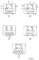
- the motor 2 has stator poles 9, 10 which form asymmetrical air gap constrictions 11, 12 (cf. Fig.2).
- the rotor 8 can thereby be de-energized the stator winding 1 only because of the reluctance moments one or the other rest position (cf. Fig. 2a or Fig.2b), but no dead center position.
- the desired starting position is shown in Figure 2d.
- To the Stator winding 1 is at least one voltage pulse one, for example negative, polarity. Stands the rotor 8 in the rest position a, then it rotates due to the voltage pulse by about 45 ° in the position of Figure 2c. Then in the currentless state the stator winding 1, the rotor 8 pivots about again 45 ° back (see Fig.2d). So at position a nothing changed in the end result that is appropriate because the rest position a and the start position d are the same.
- the voltage pulses required to reach the start position need not be whole half-waves. Around to avoid demagnetization of the rotor cut half waves.
- the first voltage pulses can have a smaller amplitude have voltage pulses as following so it doesn't overflowing the starting position comes what special could be the case from the rest position b.
- the voltage pulses mentioned are from the Control electronics 5 created via the switch 3.
- the Figures 3 and 4 show current and voltage diagrams for setting the starting position, starting and the Motor 2 starts up to synchronous speed.
- the control electronics 5 receives for example from a program control device Command to switch on the motor 2. Then at negative half-waves of switch 3, especially triac, ignited. This results in the stator winding 1 Current pulses of negative polarity, through which the rotor 8 to its starting position in the manner described above brought. In Figures 3 and 4 there are four such Current pulses shown. However, more can be done fewer current pulses are switched. Again switched so many current pulses that reaching the Starting position (see FIG. 2d) is safe.
- the control electronics 5 detects the in the de-energized state Stator winding 1, the induced voltage E and Network half-wave polarity. Have or reach them induced voltage E and the mains voltage U same Sign, then the switch 3 of the Control electronics 5 switched on, so that the Stator winding 1 is subjected to current accordingly. This is the case with the diagrams according to FIGS. 3, 4 Switch-on times t3 to t8 the case. At each Switch 3 blocks the next zero crossing of the current again. It follows that in successive half-waves of both polarities predominantly a torque in the correct direction of rotation of the engine 2 arises. To the engine-related Phase shift between current and voltage too the control electronics can take the slope into account the induced voltage and the switch switch ahead. This makes it possible to start up equalize the rotor.
- the control electronics 5 through the Evaluation of the induced voltage E (EMF) operation optimize for maximum efficiency. To do this, she measures the induced voltage E in the de-energized times of Stator winding 1 and calculates the phase position of the induced voltage E. The control of the switch 3 then takes place so that the fundamental wave of the motor current I assumes the same phase position as the induced voltage.
- EMF induced voltage
- characteristic data of the motor 2 and the load to be driven In the control electronics 5, characteristic data of the motor 2 and the load to be driven. About the Current pulse duration set at high efficiency the respective load state of the engine 2 be recognized. It can be done with the described measurement of the EMF of the motor 2 also Malfunctions, for example wrong direction of rotation or Detect running without load or blocking motor 2.
- the control electronics 5 can then special to remedy the fault Take action. For example, it can be an aggregate briefly activate the reversal of the direction of rotation of the Pump is used to remove their blockage. It is also possible that the control electronics 5 if they have a Blockage of the pump detects a restart of the pump activated.
- control electronics 5 if one Idling of the pump detects that the in currentless state affects measurable induced voltage a shutdown of the engine 2 and / or activation of another aggregate that counteracts your idling - refill water, for example - activated.
- Control electronics 5 can then be described in the Respond by stopping the engine 2 and / or another unit of the machine activates what counteracts this disorder.
Landscapes
- Engineering & Computer Science (AREA)
- Power Engineering (AREA)
- Control Of Motors That Do Not Use Commutators (AREA)
- Control Of Ac Motors In General (AREA)
- Motor And Converter Starters (AREA)
Abstract
Eine Vorrichtung zum Steuern des Anlaufs und des Betriebs eines nicht selbstanlaufenden Einphasen-Synchronmotors 2, dessen mindestens eine Statorwicklung 1 über einen von einer Steuerelektronik 5 gesteuerten Schalter 3 an das Wechselspannungsnetz 4 schaltbar ist, soll ohne Rotorlage-Sensor in richtiger Drehrichtung gestartet werden können. Die Steuerelektronik 5 erfaßt die Wechselspannungs-Polarität und im stromlosen Zustand der Statorwicklung 1 die in sie induzierte Spannung. Für eine definierte Startposition legt die Steuerelektronik 5 wenigstens einen Spannungspuls der einen Polarität an die Statorwicklung 1. Zum Anlauf des Rotors 8 legt die Steuerelektronik 5 wenigstens einen Spannungspuls der anderen Polarität an die Statorwicklung 1. Zum Hochlauf des Rotors 8 auf Synchrondrehzahl schließt die Steuerelektronik 5 den Schalter 3 jeweils dann, wenn die induzierte Spannung und die jeweilige Netzspannungshalbwelle zu einem Drehmoment in der gewünschten Drehrichtung führen. <IMAGE>A device for controlling the start-up and operation of a non-self-starting single-phase synchronous motor 2, the at least one stator winding 1 of which can be switched to the AC voltage network 4 via a switch 3 controlled by control electronics 5, should be able to be started in the correct direction of rotation without a rotor position sensor. The control electronics 5 detects the AC polarity and, in the de-energized state of the stator winding 1, the voltage induced in it. For a defined starting position, the control electronics 5 apply at least one voltage pulse of one polarity to the stator winding 1. To start the rotor 8, the control electronics 5 apply at least one voltage pulse of the other polarity to the stator winding 1. The control electronics 5 closes to start up the rotor 8 to synchronous speed the switch 3 each time the induced voltage and the respective mains voltage half-wave lead to a torque in the desired direction of rotation. <IMAGE>
Description
Die Erfindung betrifft eine Vorrichtung zum Steuern des Anlaufs und des Betriebs eines nicht selbstanlaufenden Einphasen-Synchronmotors, dessen mindestens eine Statorwicklung über einen von einer Steuerelektronik gesteuerten Schalter an die Wechselspannung eines Netzes schaltbar ist.The invention relates to a device for controlling the Start-up and operation of a non-self-starting Single-phase synchronous motor, at least one of which Stator winding via one of control electronics controlled switch to the AC voltage of a network is switchable.
Eine derartige Einrichtung ist zum Starten eines Einphasen-Synchronmotors nötig, der aufgrund seiner vergleichsweisen hohen Leistung, beispielsweise > 50 W, bauartbedingt beim Anlegen der Wechselspannung des Netzes nicht von selbst anläuft und der in einer bestimmten Drehrichtung anlaufen soll. Solche Synchronmotoren werden beispielsweise bei Haushaltsmaschinen, insbesondere für Wasserpumpen für Geschirrspülmaschinen, verwendet.Such a device is for starting one Single-phase synchronous motor necessary because of its comparatively high power, for example> 50 W, due to the design when applying the AC voltage to the network does not start by itself and that in a certain Direction of rotation should start. Such synchronous motors will be for example in household machines, especially for Water pumps for dishwashers used.
Eine Vorrichtung der eingangs genannten Art ist aus der EP 0 654 890 B1 bekannt. Dort ist zur Erfassung der jeweiligen Stellung des Rotors ein Stellungssensor nötig, der beispielsweise ein Hallsensor ist. In Abhängigkeit vom Sensorsignal und der jeweiligen Polarität der Wechselspannung wird der Schalter (Triac) gezündet, wenn der auf der geschalteten Wechselspannung beruhende Strom bei der jeweiligen Ausrichtung des Magnetfeldes des Rotors ein Drehmoment in Richtung der gewünschten Drehrichtung ergibt.A device of the type mentioned is from the EP 0 654 890 B1 known. There is to capture the a position sensor is required for the respective position of the rotor, which is, for example, a Hall sensor. Dependent on from the sensor signal and the respective polarity of the AC voltage, the switch (triac) is ignited when the current based on the switched AC voltage with the respective orientation of the magnetic field of the Rotors a torque in the direction of the desired one Direction of rotation results.
Ein Stellungssensor ist im Hinblick auf den Aufbau und die Montage aufwendig. Er muß im Motor integriert sein und mit der Steuerelektronik verbunden werden.A position sensor is in terms of structure and the assembly is complex. It must be integrated in the engine and be connected to the control electronics.
Weitere Vorrichtungen der eingangs genannten Art, die ebenfalls mit Stellungssensoren arbeiten, sind aus der EP 0 574 823 A2, der EP 0 682 404 A2, der DE 195 33 344 A1 bekannt.Other devices of the type mentioned, the also work with position sensors are from the EP 0 574 823 A2, EP 0 682 404 A2, the DE 195 33 344 A1 known.
In der EP 0 691 732 B1 ist ein Wechselrichter für einen Einphasen-Synchronmotor beschrieben, der beispielsweise für den Pumpenantrieb in einem Geschirrspüler verwendbar ist.EP 0 691 732 B1 describes an inverter for one Single-phase synchronous motor described, for example can be used for the pump drive in a dishwasher is.
Aus der DE 40 33 121 A1 ist eine Vorrichtung zum Starten eines elektrischen Einphasen-Synchronmotors bekannt, der nur für vergleichsweise kleine Leistungen ausgelegt ist und dabei selbstanlaufend ist. Die DE 40 33 121 A1 beschreibt eine Möglichkeit, einen Synchronmotor in gewünschter Drehrichtung ohne mechanische Rücklaufsperre zu starten. Für nicht selbstanlaufende Synchronmotoren ist die Vorrichtung nach der DE 40 33 121 A1 ungeeignet, da solche aufgrund ihrer Massenträgheit nicht auf Solldrehzahl beschleunigt werden könnten und mit kleinen Hin- und Herbewegungen mit Netzfrequenz stehenblieben.DE 40 33 121 A1 describes a device for starting an electric single-phase synchronous motor known is only designed for comparatively small outputs and is self-starting. DE 40 33 121 A1 describes a way in a synchronous motor Desired direction of rotation without mechanical backstop to start. For non-self-starting synchronous motors the device according to DE 40 33 121 A1 is unsuitable, because such due to their inertia Target speed could be accelerated and with small Movements with mains frequency stopped.
In der EP 0 495 611 A2 ist eine Vorrichtung zum Starten eines 3-phasigen Motors für eine Magnetplatte beschrieben. Nur zur Steuerung der Solldrehzahl wird die in den Wicklungen induzierte Spannung bzw. die elektromotorische Kraft ausgewertet.EP 0 495 611 A2 describes a device for starting of a 3-phase motor for a magnetic disk described. The is only used to control the target speed induced voltage in the windings or the electromotive force evaluated.
Aus der DE 44 18 721 A1 ist ein Steuerungsverfahren für eine Laugenumwälzpumpe einer Geschirrspülmaschine bekannt. Es soll das kontinuierliche Fördern der nicht selbstansaugenden Pumpe überwacht werden. Drehzahlschwankungen sowie Schwankungen des Motorstroms werden zur Beeinflussung des Programmablaufs verarbeitet. DE 44 18 721 A1 describes a control method for a lye circulation pump of a dishwasher known. It is not meant to promote the continuous self-priming pump can be monitored. Speed fluctuations and fluctuations in the motor current are processed to influence the program flow.
Aufgabe der Erfindung ist es, eine Vorrichtung der eingangs genannten Art vorzuschlagen, mit der ein an sich nicht selbstanlaufender Einphasen-Synchronmotor in richtiger Drehrichtung startbar ist, ohne daß ein Sensor nötig ist, der die Lage des Rotors erfaßt.The object of the invention is a device of to propose the type mentioned at the beginning, with which a not self-starting single-phase synchronous motor in correct direction of rotation can be started without a sensor is necessary, which detects the position of the rotor.
Erfindungsgemäß ist obige Aufgabe durch die Merkmale des
kennzeichnenden Teils des Anspruchs 1 gelöst.According to the invention, the above object is characterized by the features of
characterizing part of
Die Vorrichtung veranlaßt beim Einschalten wenigstens
folgende drei Vorgänge:
Ein Drehmoment in der gewünschten Drehrichtung entsteht dann, wenn die induzierte Spannung und die jeweilige Netzhalbwelle bzw. der entsprechende Strom die gleiche Polarität haben. Es kann auch von der Steuerelektronik die Steigung der induzierten Spannung (EMK) ausgewertet werden, um das Hochlaufen des Motors auf Synchrondrehzahl zu vergleichmäßigen.A torque is created in the desired direction of rotation then when the induced voltage and the respective Mains half wave or the corresponding current the same Have polarity. It can also be from the control electronics evaluated the slope of the induced voltage (EMF) to start up the motor to synchronous speed to even out.
Durch die Erfassung der induzierten Spannung (EMK) ist es auch möglich, weitere Betriebszustände, insbesondere Störungen, auszuwerten. Hierauf beziehen sich Unteransprüche.By detecting the induced voltage (EMF) it is also possible other operating states, in particular Disorders to evaluate. Refer to this Subclaims.
Ein Ausführungsbeispiel der Erfindung ergibt sich aus der
folgenden Beschreibung. In der Zeichnung zeigen:
Ein Einphasen-Synchronmotor 2, der beispielsweise dem
Antrieb einer Wasserpumpe einer Spülmaschine dient, weist
eine Statorwicklung 1 auf, die über einen elektronischen
Schalter 3, insbesondere Triac oder optisch triggerbarer
Triac, an das Wechselstromnetz 4 schaltbar ist. Den
Schalter 3 steuert eine Steuerelektronik 5, die
beispielsweise mit einem Mikroprozessor bzw.
Mikrocontroller arbeitet und Teil einer Programmsteuer-Einrichtung
sein kann.A single-phase
Die Steuerelektronik 5 wertet über einen Eingang 6 die
jeweilige Polarität der jeweiligen Netzhalbwellen und
über einen Eingang 7 die an der Statorwicklung 1
abfallende Spannung Um bzw. E folgendermaßen aus:The
Wenn der Schalter 3 sperrt, ist der Motorstrom I gleich
Null. Der permanentmagnetische Rotor 8 bleibt dabei nicht
sofort stehen, sondern dreht aufgrund seiner
Massenträgheit weiter, wodurch in die Statorwicklung 1
eine Spannung entsprechend der EMK induziert wird.
Zumindest deren Polarität wird von der Steuerelektronik 5
ausgewertet.If the switch 3 blocks, the motor current I is the same
Zero. The permanent
Der Motor 2 weist Ständerpole 9,10 auf, welche
unsymmetrische Luftspaltverengungen 11,12 bilden (vgl.
Fig.2). Der Rotor 8 kann dadurch im unbestromten Zustand
der Statorwicklung 1 wegen der Reluktanzmomente nur die
eine oder die andere Ruheposition (vgl. Fig. 2a oder
Fig.2b), jedoch keine Totpunktstellung, annehmen.The
In der Ruheposition a liegt der Nordpol N des Rotors 8
bei der Luftspaltverengung 11. In der Ruheposition b
liegt der Südpol S des Rotors 8 bei der
Luftspaltverengung 11. Die beiden möglichen
Ruhepositionen machen die Anlauf-Drehrichtung des Rotors
8 unsicher. Wie eine definierte Startposition des Rotors
8 erreicht wird, ist anhand von Figur 2 beschrieben.In the rest position a, the north pole N of the
Die gewünschte Startposition zeigt Figur 2d. An die
Statorwicklung 1 wird wenigstens ein Spannungspuls der
einen, beispielsweise negativen, Polarität gelegt. Steht
der Rotor 8 dabei in der Ruheposition a, dann dreht er
infolge des Spannungspulses um etwa 45° in die Stellung
der Figur 2c. Im dann anschließenden stromlosen Zustand
der Statorwicklung 1 schwenkt der Rotor 8 wieder um etwa
45° zurück (vgl. Fig.2d). An der Stellung a hat sich also
im Endergebnis nichts geändert, was sachgerecht ist, weil
die Ruheposition a und die Startposition d gleich sind.The desired starting position is shown in Figure 2d. To the
Stator winding 1 is at least one voltage pulse
one, for example negative, polarity. Stands
the
Steht jedoch der Rotor 8 in der Ruheposition b, dann
dreht er infolge des genannten Spannungspulses um etwa
135° in die Stellung der Figur 2c. Im dann anschließenden
stromlosen Zustand der Statorwicklung 1 schwenkt der
Nordpol N - um etwa 45° - zur Luftspaltverengung 11. Es
ist damit der Rotor 8 aus der Ruheposition b in die
Startposition d gebracht. However, if the
Um dann anschließend den Motor 2 zu starten, werden
Spannungspulse der anderen, im Beispielsfalle positiven,
Polarität an die Statorwicklung 1 gelegt, wodurch der
Rotor 8 in Richtung des Pfeiles der Figur 2e anläuft.In order to then start
Die Spannungspulse, die zum Erreichen der Startposition angelegt werden, müssen keine ganzen Halbwellen sein. Um eine Demagnetisierung des Rotors zu vermeiden, werden nur angeschnittene Halbwellen angelegt.The voltage pulses required to reach the start position need not be whole half-waves. Around to avoid demagnetization of the rotor cut half waves.
Mehrere Spannungspulse anzulegen, erhöht die Sicherheit des Erreichens der Startposition (vgl. Fig.2d). Die ersten Spannungspulse können eine kleinere Amplitude haben als folgende Spannungspulse, damit es nicht zu einem Überlaufen der Startposition kommt, was speziell aus der Ruheposition b der Fall sein könnte.Applying several voltage pulses increases security reaching the starting position (see Fig.2d). The first voltage pulses can have a smaller amplitude have voltage pulses as following so it doesn't overflowing the starting position comes what special could be the case from the rest position b.
Die genannten Spannungspulse werden von der
Steuerelektronik 5 über den Schalter 3 angelegt. Die
Figuren 3 und 4 Zeigen Strom- und Spannungsdiagramme für
das Einstellen der Startposition, das Starten und den
Hochlauf des Motors 2 auf Synchrondrehzahl.The voltage pulses mentioned are from the
Zu einem Zeitpunkt t0 erhält die Steuerelektronik 5,
beispielsweise von einer Programmsteuereinrichtung, einen
Befehl zum Einschalten des Motors 2. Daraufhin wird bei
negativen Halbwellen der Schalter 3, speziell Triac,
gezündet. Damit ergeben sich in der Statorwicklung 1
Stromimpulse negativer Polarität, durch die der Rotor 8
in der oben beschriebenen Weise in seine Startposition
gebracht wird. In den Figuren 3 und 4 sind vier solche
Stromimpulse gezeigt. Es können jedoch auch mehr oder
weniger Stromimpulse geschaltet werden. Jedenfalls werden
so viele Stromimpulse geschaltet, daß das Erreichen der
Startposition (vgl. Fig. 2d) sicher ist.At a time t0, the
Ab einem späteren Zeitpunkt t1 wird der Motor 2
gestartet. Hierzu werden mittels des Schalters 3 mehrere
Netzhalbwellen oder angeschnittene Netzhalbwellen der
anderen Polarität, im Beispielsfalle also positive
Netzhalbwellen, auf die Statorwicklung 1 geschaltet. Der
Rotor 8 beginnt nun in der gewünschten Drehrichtung zu
drehen. In den Figuren 3 und 4 sind für das Starten Zwei
positive Netzhalbwellen vorgesehen. Es können auch mehr
oder weniger solcher Netzhalbwellen für das Starten
verwendet werden.From a later point in time t1, the
Ab einem Zeitpunkt t2 wird das Beschleunigen (Hochlaufen)
des Rotors 8 auf Synchrondrehzahl durch Zünden des
Schalters 3 in aufeinanderfolgenden positiven und
negativen Halbwellen eingeleitet. Jeweils wenn der
Schalter 3 gesperrt ist, der Strom durch die
Statorwicklung 1 also Null ist, wird die sich durch den
aufgrund seiner Trägheit weiterdrehenden Rotor 8 in die
Statorwicklung 1 induzierte Spannung E (EMK) von der
Steuerelektronik 5 gemessen. In den Figuren 3 und 4 ist
die EMK E punktiert durchgehend angedeutet. Messen läßt
sie sich nur, wenn der Schalter 3 gesperrt ist. In Figur
4 ist, um dies zu verdeutlichen, die an der
Statorwicklung 1 abfallende, meßbare Spannung Um gezeigt.
Ersichtlich entspricht diese bei leitendem Schalter 3 der
Netzspannung und bei gesperrtem Schalter 3 der
induzierten Spannung E.From a time t2, the acceleration (ramp-up)
of the
Die Steuerelektronik 5 erfaßt im stromlosen Zustand der
Statorwicklung 1 die induzierte Spannung E und die
Polarität der Netzhalbwellen. Haben bzw. erreichen die
induzierte Spannung E und die Netzspannung U gleiches
Vorzeichen, dann wird der Schalter 3 von der
Steuerelektronik 5 leitend geschaltet, so daß die
Statorwicklung 1 entsprechend strombeaufschlagt wird.
Dies ist bei den Diagrammen nach den Figuren 3,4 in den
Einschaltzeitpunkten t3 bis t8 der Fall. Beim jeweils
nächsten Nulldurchgang des Stroms sperrt der Schalter 3
wieder. Es ergibt sich daraus, daß in
aufeinanderfolgenden Halbwellen beider Polaritäten
überwiegend ein Drehmoment in der richtigen Drehrichtung
des Motors 2 entsteht. Um die motorbedingte
Phasenverschiebung zwischen Strom und Spannung zu
berücksichtigen, kann die Steuerelektronik die Steigung
der induzierten Spannung erfassen und dem Schalter
voreilend schalten. Es läßt sich dadurch das Hochlaufen
des Rotors vergleichmäßigen.The
Ist der Rotor 8 auf Synchrondrehzahl hochgelaufen, was in
den Figuren 3 und 4 etwa nach dem Zeitpunkt t9 der Fall
ist, dann kann die Steuerelektronik 5 durch die
Auswertung der induzierten Spannung E (EMK) den Betrieb
auf maximalen Wirkungsgrad optimieren. Hierzu mißt sie
die induzierte Spannung E in den stromlosen Zeiten der
Statorwicklung 1 und errechnet daraus die Phasenlage der
induzierten Spannung E. Die Steuerung des Schalters 3
erfolgt dann so, daß die Grundwelle des Motorstroms I
dieselbe Phasenlage annimmt, wie die induzierte Spannung.If the
In der Steuerelektronik 5 können Kenndaten des Motors 2
und der anzutreibenden Last gespeichert sein. Über die
Stromimpulsdauer, die bei hohem Wirkungsgrad eingestellt
wird, kann der jeweilige Belastungszustand des Motors 2
erkannt werden. Es lassen sich damit durch die
beschriebene Messung der EMK des Motors 2 auch
Störzustände, beispielsweise falsche Drehrichtung oder
Laufen ohne Last oder Blockieren des Motors 2 erfassen.In the
Blockiert beispielsweise eine vom Motor 2 anzutreibende
Pumpe eines Haushaltsgeräts, wie Spülmaschine oder
Waschmaschine, dann ist im stromlosen Zustand der
Statorwicklung 1 keine induzierte Spannung meßbar, weil
der Rotor 8 nicht weiterdreht, obwohl dies die
Steuerelektronik 5 an sich erwartet. Die Steuerelektronik
5 kann hierauf zur Behebung der Störung besondere
Maßnahmen einleiten. Beispielsweise kann sie ein Aggregat
kurzzeitig aktivieren, das der Drehrichtungsumkehr der
Pumpe dient, um deren Blockierung zu beseitigen. Es ist
auch möglich, daß die Steuerelektronik 5, wenn sie eine
Blockierung der Pumpe erfaßt, einen Neustart der Pumpe
aktiviert.For example, blocks one to be driven by
Ähnlich kann die Steuerelektronik 5, wenn sie ein
Leerlaufen der Pumpe erfaßt, das sich auf die im
stromlosen Zustand meßbare induzierte Spannung auswirkt,
ein Abschalten des Motors 2 und/oder die Aktivierung
eines anderen Aggregats, das dein Leerlaufen entgegenwirkt
- beispielsweise Wasser nachfüllen -, aktiviert.Similarly, the
Auch bei einer Überlast des Motors 2 ist eine
ungewöhnliche Änderung der im stromlosen Zustand
gemessenen induzierten Spannung gegeben. Die
Steuerelektronik 5 kann hierauf in der beschriebenen
Weise dadurch reagieren, daß sie den Motor 2 stoppt
und/oder ein anderes Aggregat der Maschine aktiviert, was
dieser Störung entgegenwirkt.Even if the
Claims (8)
dadurch gekennzeichnet,
characterized,
dadurch gekennzeichnet,
characterized,
dadurch gekennzeichnet,
characterized,
dadurch gekennzeichnet,
characterized,
dadurch gekennzeichnet,
characterized,
dadurch gekennzeichnet,
characterized,
dadurch gekennzeichnet,
characterized,
dadurch gekennzeichnet,
characterized,
Applications Claiming Priority (2)
| Application Number | Priority Date | Filing Date | Title |
|---|---|---|---|
| DE19813095A DE19813095A1 (en) | 1998-03-25 | 1998-03-25 | Device for controlling a single-phase synchronous motor |
| DE19813095 | 1998-03-25 |
Publications (3)
| Publication Number | Publication Date |
|---|---|
| EP0945973A2 true EP0945973A2 (en) | 1999-09-29 |
| EP0945973A3 EP0945973A3 (en) | 2001-06-13 |
| EP0945973B1 EP0945973B1 (en) | 2002-06-26 |
Family
ID=7862248
Family Applications (1)
| Application Number | Title | Priority Date | Filing Date |
|---|---|---|---|
| EP99105656A Expired - Lifetime EP0945973B1 (en) | 1998-03-25 | 1999-03-19 | Control device for a single phase synchronous motor |
Country Status (3)
| Country | Link |
|---|---|
| EP (1) | EP0945973B1 (en) |
| DE (2) | DE19813095A1 (en) |
| ES (1) | ES2179568T3 (en) |
Cited By (22)
| Publication number | Priority date | Publication date | Assignee | Title |
|---|---|---|---|---|
| EP1443635A1 (en) * | 2003-01-21 | 2004-08-04 | Grundfos A/S | Method for driving a firing angle |
| EP1154558A3 (en) * | 2000-05-12 | 2004-11-17 | Aradex AG | Method for controlling a synchronous motor |
| WO2009001291A3 (en) * | 2007-06-26 | 2009-04-09 | Askoll P & C S R L | A control system without position sensors for a synchronous electric motor |
| EP1387087A3 (en) * | 2002-07-29 | 2009-10-28 | Wilo Ag | Method for determining the flow rate in a pump |
| JP2010503367A (en) * | 2006-09-04 | 2010-01-28 | ウェリントン ドライブ テクノロジーズ リミテッド | Control of synchronous electric machine |
| ITPD20080313A1 (en) * | 2008-10-29 | 2010-04-30 | Newa Tecno Ind S R L | ELECTRONIC START-UP AND CONTROL DEVICE FOR SINGLE-PHASE SYNCHRONOUS ELECTRIC MOTORS WITH PERMANENT MAGNET ROTOR |
| ITTO20090166A1 (en) * | 2009-03-04 | 2010-09-05 | Askoll P & C S R L | PROCEDURE FOR MONITORING THE LOAD OF A SYNCHRONOUS ELECTRIC CURRENT MOTOR WITH ALTERNATIVE CURRENT AND PERMANENT MAGNET ROTOR |
| FR2951267A1 (en) * | 2009-10-14 | 2011-04-15 | Peugeot Citroen Automobiles Sa | Device for detecting level of liquid in tank in motor vehicle i.e. automobile, has pump for extracting liquid from tank, and determination unit for determining level of liquid in tank according to comparison result |
| EP2410651A1 (en) * | 2010-07-23 | 2012-01-25 | Askoll Holding S.r.l. | Method for starting a permanent magnet single-phase synchronous electric motor and electronic device for implementing said method |
| EP2439840A1 (en) * | 2010-10-11 | 2012-04-11 | Askoll Holding S.r.l. | Method for controlling the discharge pump of a household appliance and processing unit for implementing said method |
| CN102904510A (en) * | 2011-07-25 | 2013-01-30 | 阿思科尔控股责任有限公司 | Starting method for permanent magnet single-phase synchronous motor and electronic device for implementing same |
| EP3222853A3 (en) * | 2016-03-22 | 2018-01-10 | Whirlpool Corporation | Multi-outlet fluid flow system for an appliance incorporating a bi-directional motor |
| EP3447903A1 (en) * | 2017-08-25 | 2019-02-27 | Johnson Electric International AG | Motor driving circuit, motor driving method, and motor utilizing the same |
| US10234065B2 (en) | 2015-10-27 | 2019-03-19 | Whirlpool Corporation | Collet securing device for joining two fluid lines and providing lateral support at the connection of the two fluid lines |
| US10480117B2 (en) | 2017-02-27 | 2019-11-19 | Whirlpool Corporation | Self cleaning sump cover |
| US10619289B2 (en) | 2017-02-27 | 2020-04-14 | Whirlpool Corporation | Self cleaning diverter valve |
| US10634412B2 (en) | 2017-04-10 | 2020-04-28 | Whirlpool Corporation | Concealed upstream air tower guide vanes |
| US10655266B2 (en) | 2016-11-30 | 2020-05-19 | Whirlpool Corporation | Lint processing fluid pump for a laundry appliance |
| US10662574B2 (en) | 2017-02-27 | 2020-05-26 | Whirlpool Corporation | Self cleaning heater exchanger plate |
| US10697700B2 (en) | 2018-01-17 | 2020-06-30 | Whirlpool Corporation | Refrigeration water dispensing system |
| IT202100026357A1 (en) * | 2021-10-15 | 2022-01-15 | Fise Spa | METHOD FOR STARTING AND CONTROLING A SINGLE-PHASE BRUSHLESS MOTOR |
| EP4156496A1 (en) * | 2021-09-28 | 2023-03-29 | Miele & Cie. KG | Propulsion system |
Family Cites Families (6)
| Publication number | Priority date | Publication date | Assignee | Title |
|---|---|---|---|---|
| JPS61240868A (en) * | 1985-04-16 | 1986-10-27 | Matsushita Seiko Co Ltd | Controller of synchronous motor |
| DE3638440A1 (en) * | 1986-11-11 | 1988-06-01 | Bosch Gmbh Robert | SINGLE PHASE MACHINE |
| FR2653613B1 (en) * | 1989-10-20 | 1994-11-18 | Eaton Controls Sa | METHOD AND DEVICE FOR STARTING A SINGLE PHASE SYNCHRONOUS ELECTRIC MOTOR. |
| ATE148600T1 (en) * | 1993-11-22 | 1997-02-15 | Siemens Ag | DEVICE FOR DRIVING A SINGLE-PHASE SYNCHRONOUS MOTOR, IN PARTICULAR FOR DRIVING A PUMP DRIVE IN A HOUSEHOLD APPLIANCE |
| AT402869B (en) * | 1994-02-03 | 1997-09-25 | Muehlegger Werner Dr | ELECTRONIC STARTING DEVICE FOR STARTING A SINGLE-PHASE SYNCHRONOUS MACHINE |
| IT1269755B (en) * | 1994-05-11 | 1997-04-15 | Sisme | ELECTRONIC DEVICE FOR STARTING AND CONTROL OF A SINGLE-PHASE SYNCHRONOUS MOTOR WITH PERMANENT MAGNETS |
-
1998
- 1998-03-25 DE DE19813095A patent/DE19813095A1/en not_active Withdrawn
-
1999
- 1999-03-19 ES ES99105656T patent/ES2179568T3/en not_active Expired - Lifetime
- 1999-03-19 EP EP99105656A patent/EP0945973B1/en not_active Expired - Lifetime
- 1999-03-19 DE DE59901834T patent/DE59901834D1/en not_active Expired - Lifetime
Cited By (42)
| Publication number | Priority date | Publication date | Assignee | Title |
|---|---|---|---|---|
| EP1154558A3 (en) * | 2000-05-12 | 2004-11-17 | Aradex AG | Method for controlling a synchronous motor |
| EP1387087A3 (en) * | 2002-07-29 | 2009-10-28 | Wilo Ag | Method for determining the flow rate in a pump |
| WO2004066484A1 (en) * | 2003-01-21 | 2004-08-05 | Grundfos A/S | Method for controlling the firing angle |
| EP1443635A1 (en) * | 2003-01-21 | 2004-08-04 | Grundfos A/S | Method for driving a firing angle |
| JP2010503367A (en) * | 2006-09-04 | 2010-01-28 | ウェリントン ドライブ テクノロジーズ リミテッド | Control of synchronous electric machine |
| EP2060002A4 (en) * | 2006-09-04 | 2010-08-11 | Wellington Drive Technologies | CONTROL OF SYNCHRONOUS ELECTRIC MACHINES |
| US8120297B2 (en) | 2006-09-04 | 2012-02-21 | Wellington Drive Technologies Limited | Control of synchronous electrical machines |
| KR101437716B1 (en) * | 2007-06-26 | 2014-09-18 | 아스콜 피 앤 씨 에스.알.엘. | A control system without position sensors for a synchronous electric motor |
| WO2009001291A3 (en) * | 2007-06-26 | 2009-04-09 | Askoll P & C S R L | A control system without position sensors for a synchronous electric motor |
| CN101711453B (en) * | 2007-06-26 | 2012-05-30 | 阿思科尔P&C责任有限公司 | Control system without position sensor for synchronous motor |
| US8222856B2 (en) | 2007-06-26 | 2012-07-17 | Askoll P&C S.R.L. | Control system without position sensors for a synchronous electric motor |
| ITPD20080313A1 (en) * | 2008-10-29 | 2010-04-30 | Newa Tecno Ind S R L | ELECTRONIC START-UP AND CONTROL DEVICE FOR SINGLE-PHASE SYNCHRONOUS ELECTRIC MOTORS WITH PERMANENT MAGNET ROTOR |
| ITTO20090166A1 (en) * | 2009-03-04 | 2010-09-05 | Askoll P & C S R L | PROCEDURE FOR MONITORING THE LOAD OF A SYNCHRONOUS ELECTRIC CURRENT MOTOR WITH ALTERNATIVE CURRENT AND PERMANENT MAGNET ROTOR |
| FR2951267A1 (en) * | 2009-10-14 | 2011-04-15 | Peugeot Citroen Automobiles Sa | Device for detecting level of liquid in tank in motor vehicle i.e. automobile, has pump for extracting liquid from tank, and determination unit for determining level of liquid in tank according to comparison result |
| EP2410651A1 (en) * | 2010-07-23 | 2012-01-25 | Askoll Holding S.r.l. | Method for starting a permanent magnet single-phase synchronous electric motor and electronic device for implementing said method |
| US8164286B2 (en) | 2010-07-23 | 2012-04-24 | Askoll Holding S.R.L. | Method for starting a permanent magnet single-phase synchronous electric motor and electronic device for implementing said method |
| CN102347723A (en) * | 2010-07-23 | 2012-02-08 | 阿思科尔控股责任有限公司 | Method for starting a permanent magnet single-phase synchronous electric motor and electronic device for implementing said method |
| CN102347723B (en) * | 2010-07-23 | 2015-06-10 | 阿思科尔控股责任有限公司 | Method for starting a permanent magnet single-phase synchronous electric motor and electronic device for implementing said method |
| US9065363B2 (en) | 2010-07-23 | 2015-06-23 | Askoll Holding S.R.L. | Method for starting a permanent magnet single-phase synchronous electric motor and electronic device for implementing said method |
| EP2421144A3 (en) * | 2010-07-23 | 2016-01-06 | Askoll Holding S.r.l. | Method for starting a permanent magnet single-phase synchronous electric motor and electronic device for implementing said method |
| CN102444570A (en) * | 2010-10-11 | 2012-05-09 | 艾斯科尔侯丁有限公司 | Method for controlling a discharge pump of a household appliance and processing unit for implementing the method |
| EP2439840A1 (en) * | 2010-10-11 | 2012-04-11 | Askoll Holding S.r.l. | Method for controlling the discharge pump of a household appliance and processing unit for implementing said method |
| US8766580B2 (en) | 2010-10-11 | 2014-07-01 | Askoll Holding S.R.L. | Method for controlling the discharge pump of a household appliance and processing unit for implementing said method |
| CN102904510A (en) * | 2011-07-25 | 2013-01-30 | 阿思科尔控股责任有限公司 | Starting method for permanent magnet single-phase synchronous motor and electronic device for implementing same |
| CN102904510B (en) * | 2011-07-25 | 2016-05-18 | 阿思科尔控股责任有限公司 | Permanent magnetism single-phase synchronous motor starting method and realize the electronic equipment of the method |
| US10234065B2 (en) | 2015-10-27 | 2019-03-19 | Whirlpool Corporation | Collet securing device for joining two fluid lines and providing lateral support at the connection of the two fluid lines |
| EP3222853A3 (en) * | 2016-03-22 | 2018-01-10 | Whirlpool Corporation | Multi-outlet fluid flow system for an appliance incorporating a bi-directional motor |
| US10557469B2 (en) | 2016-03-22 | 2020-02-11 | Whirlpool Corporation | Multi-outlet fluid flow system for an appliance incorporating a bi-directional motor |
| US10655266B2 (en) | 2016-11-30 | 2020-05-19 | Whirlpool Corporation | Lint processing fluid pump for a laundry appliance |
| US11603615B2 (en) | 2017-02-27 | 2023-03-14 | Whirlpool Corporation | Self cleaning sump cover |
| US10480117B2 (en) | 2017-02-27 | 2019-11-19 | Whirlpool Corporation | Self cleaning sump cover |
| US10619289B2 (en) | 2017-02-27 | 2020-04-14 | Whirlpool Corporation | Self cleaning diverter valve |
| US10662574B2 (en) | 2017-02-27 | 2020-05-26 | Whirlpool Corporation | Self cleaning heater exchanger plate |
| US11035073B2 (en) | 2017-02-27 | 2021-06-15 | Whirlpool Corporation | Self cleaning sump cover |
| US11802360B2 (en) | 2017-02-27 | 2023-10-31 | Whirlpool Corporation | Self cleaning sump cover |
| US10634412B2 (en) | 2017-04-10 | 2020-04-28 | Whirlpool Corporation | Concealed upstream air tower guide vanes |
| EP3447903A1 (en) * | 2017-08-25 | 2019-02-27 | Johnson Electric International AG | Motor driving circuit, motor driving method, and motor utilizing the same |
| US10707787B2 (en) | 2017-08-25 | 2020-07-07 | Johnson Electric International AG | Motor driving circuit, motor driving method, and motor utilizing the same |
| US10697700B2 (en) | 2018-01-17 | 2020-06-30 | Whirlpool Corporation | Refrigeration water dispensing system |
| US11592232B2 (en) | 2018-01-17 | 2023-02-28 | Whirlpool Corporation | Refrigeration water dispensing system |
| EP4156496A1 (en) * | 2021-09-28 | 2023-03-29 | Miele & Cie. KG | Propulsion system |
| IT202100026357A1 (en) * | 2021-10-15 | 2022-01-15 | Fise Spa | METHOD FOR STARTING AND CONTROLING A SINGLE-PHASE BRUSHLESS MOTOR |
Also Published As
| Publication number | Publication date |
|---|---|
| ES2179568T3 (en) | 2003-01-16 |
| EP0945973A3 (en) | 2001-06-13 |
| DE59901834D1 (en) | 2002-08-01 |
| EP0945973B1 (en) | 2002-06-26 |
| DE19813095A1 (en) | 1999-09-30 |
Similar Documents
| Publication | Publication Date | Title |
|---|---|---|
| EP0945973B1 (en) | Control device for a single phase synchronous motor | |
| DE69727651T2 (en) | Device for controlling a synchronous motor with a permanent magnet rotor | |
| DE69505298T2 (en) | Electronic circuit for starting and controlling a single-phase synchronous motor with permanent magnets. | |
| EP3413458B1 (en) | Control for 1-phase synchronous motor | |
| WO1998036123A2 (en) | Laundry treating equipment with a driving motor mounted on the drum shaft | |
| DE19701856A1 (en) | Electronic start-up and operation control for a single-phase synchronous motor | |
| EP0957570B1 (en) | Device for controlling a single phase synchronous motor | |
| DE19539656A1 (en) | Method for starting variable-speed electric drives | |
| EP0654890B2 (en) | Device for driving a single phase synchronous motor, especially for driving a pump in a household appliance | |
| DE2755333C2 (en) | ||
| DE602005004418T2 (en) | CONTROL UNIT FOR AN ELECTRIC SYNCHRONOUS MOTOR | |
| EP1443635B1 (en) | Method for controlling a firing angle and single phase AC fed electric motor | |
| DE10014174A1 (en) | Brake module | |
| DE102016114030A1 (en) | Integrated circuit, driver circuit for a motor, motor assembly and equipment therewith | |
| DE9407983U1 (en) | Device for driving a single-phase synchronous motor, in particular for driving a pump drive in a household appliance | |
| AT402869B (en) | ELECTRONIC STARTING DEVICE FOR STARTING A SINGLE-PHASE SYNCHRONOUS MACHINE | |
| DE69622515T2 (en) | Device and method for reducing iron losses in a switched reluctance machine | |
| DE19857695C2 (en) | Method and device for controlling the outlet of an induction machine | |
| EP1508810A1 (en) | Control circuit for a switched reluctance motor | |
| DE2217847A1 (en) | CIRCUIT ARRANGEMENT FOR REVERSING THE DIRECTION OF ROTATION OF AN ELECTRIC MOTOR, IN PARTICULAR A WASHING MACHINE | |
| BE1029031B1 (en) | Process for thermal monitoring of at least two-phase brushless motor | |
| DE3607162A1 (en) | AC motor especially for circulation pumps | |
| EP3331157B1 (en) | Method and control unit for controlling a switched reluctance motor | |
| EP3301807A1 (en) | Two strand synchronous drive | |
| DE1918257A1 (en) | Brushless and commutator-free 3-phase AC motor with variable speed |
Legal Events
| Date | Code | Title | Description |
|---|---|---|---|
| PUAI | Public reference made under article 153(3) epc to a published international application that has entered the european phase |
Free format text: ORIGINAL CODE: 0009012 |
|
| AK | Designated contracting states |
Kind code of ref document: A2 Designated state(s): DE ES FR GB IT |
|
| AX | Request for extension of the european patent |
Free format text: AL;LT;LV;MK;RO;SI |
|
| RAP1 | Party data changed (applicant data changed or rights of an application transferred) |
Owner name: DIEHL AKO STIFTUNG & CO. KG |
|
| PUAL | Search report despatched |
Free format text: ORIGINAL CODE: 0009013 |
|
| AK | Designated contracting states |
Kind code of ref document: A3 Designated state(s): AT BE CH CY DE DK ES FI FR GB GR IE IT LI LU MC NL PT SE |
|
| AX | Request for extension of the european patent |
Free format text: AL;LT;LV;MK;RO;SI |
|
| 17P | Request for examination filed |
Effective date: 20010509 |
|
| GRAG | Despatch of communication of intention to grant |
Free format text: ORIGINAL CODE: EPIDOS AGRA |
|
| 17Q | First examination report despatched |
Effective date: 20010905 |
|
| GRAG | Despatch of communication of intention to grant |
Free format text: ORIGINAL CODE: EPIDOS AGRA |
|
| GRAH | Despatch of communication of intention to grant a patent |
Free format text: ORIGINAL CODE: EPIDOS IGRA |
|
| AKX | Designation fees paid |
Free format text: DE ES FR GB IT |
|
| GRAH | Despatch of communication of intention to grant a patent |
Free format text: ORIGINAL CODE: EPIDOS IGRA |
|
| GRAA | (expected) grant |
Free format text: ORIGINAL CODE: 0009210 |
|
| AK | Designated contracting states |
Kind code of ref document: B1 Designated state(s): DE ES FR GB IT |
|
| REG | Reference to a national code |
Ref country code: GB Ref legal event code: FG4D Free format text: NOT ENGLISH |
|
| REF | Corresponds to: |
Ref document number: 59901834 Country of ref document: DE Date of ref document: 20020801 |
|
| GBT | Gb: translation of ep patent filed (gb section 77(6)(a)/1977) |
Effective date: 20020925 |
|
| ET | Fr: translation filed | ||
| REG | Reference to a national code |
Ref country code: ES Ref legal event code: FG2A Ref document number: 2179568 Country of ref document: ES Kind code of ref document: T3 |
|
| PLBE | No opposition filed within time limit |
Free format text: ORIGINAL CODE: 0009261 |
|
| STAA | Information on the status of an ep patent application or granted ep patent |
Free format text: STATUS: NO OPPOSITION FILED WITHIN TIME LIMIT |
|
| 26N | No opposition filed |
Effective date: 20030327 |
|
| PGFP | Annual fee paid to national office [announced via postgrant information from national office to epo] |
Ref country code: FR Payment date: 20050128 Year of fee payment: 7 |
|
| PGFP | Annual fee paid to national office [announced via postgrant information from national office to epo] |
Ref country code: ES Payment date: 20050301 Year of fee payment: 7 |
|
| PGFP | Annual fee paid to national office [announced via postgrant information from national office to epo] |
Ref country code: GB Payment date: 20050311 Year of fee payment: 7 |
|
| PG25 | Lapsed in a contracting state [announced via postgrant information from national office to epo] |
Ref country code: GB Free format text: LAPSE BECAUSE OF NON-PAYMENT OF DUE FEES Effective date: 20060319 |
|
| PG25 | Lapsed in a contracting state [announced via postgrant information from national office to epo] |
Ref country code: ES Free format text: LAPSE BECAUSE OF NON-PAYMENT OF DUE FEES Effective date: 20060321 |
|
| PGFP | Annual fee paid to national office [announced via postgrant information from national office to epo] |
Ref country code: IT Payment date: 20060331 Year of fee payment: 8 |
|
| GBPC | Gb: european patent ceased through non-payment of renewal fee |
Effective date: 20060319 |
|
| REG | Reference to a national code |
Ref country code: FR Ref legal event code: ST Effective date: 20061130 |
|
| REG | Reference to a national code |
Ref country code: ES Ref legal event code: FD2A Effective date: 20060321 |
|
| PG25 | Lapsed in a contracting state [announced via postgrant information from national office to epo] |
Ref country code: FR Free format text: LAPSE BECAUSE OF NON-PAYMENT OF DUE FEES Effective date: 20060331 |
|
| PG25 | Lapsed in a contracting state [announced via postgrant information from national office to epo] |
Ref country code: IT Free format text: LAPSE BECAUSE OF NON-PAYMENT OF DUE FEES Effective date: 20070319 |
|
| PGFP | Annual fee paid to national office [announced via postgrant information from national office to epo] |
Ref country code: DE Payment date: 20100519 Year of fee payment: 12 |
|
| PG25 | Lapsed in a contracting state [announced via postgrant information from national office to epo] |
Ref country code: DE Free format text: LAPSE BECAUSE OF NON-PAYMENT OF DUE FEES Effective date: 20111001 |
|
| REG | Reference to a national code |
Ref country code: DE Ref legal event code: R119 Ref document number: 59901834 Country of ref document: DE Effective date: 20111001 |