EP0945400A2 - Process for the preparation of nitric acid - Google Patents
Process for the preparation of nitric acid Download PDFInfo
- Publication number
- EP0945400A2 EP0945400A2 EP99105223A EP99105223A EP0945400A2 EP 0945400 A2 EP0945400 A2 EP 0945400A2 EP 99105223 A EP99105223 A EP 99105223A EP 99105223 A EP99105223 A EP 99105223A EP 0945400 A2 EP0945400 A2 EP 0945400A2
- Authority
- EP
- European Patent Office
- Prior art keywords
- compressor
- pressure
- gas
- shaft
- nitrous
- Prior art date
- Legal status (The legal status is an assumption and is not a legal conclusion. Google has not performed a legal analysis and makes no representation as to the accuracy of the status listed.)
- Granted
Links
Images


Classifications
-
- C—CHEMISTRY; METALLURGY
- C01—INORGANIC CHEMISTRY
- C01B—NON-METALLIC ELEMENTS; COMPOUNDS THEREOF; METALLOIDS OR COMPOUNDS THEREOF NOT COVERED BY SUBCLASS C01C
- C01B21/00—Nitrogen; Compounds thereof
- C01B21/20—Nitrogen oxides; Oxyacids of nitrogen; Salts thereof
- C01B21/24—Nitric oxide (NO)
- C01B21/26—Preparation by catalytic or non-catalytic oxidation of ammonia
-
- Y—GENERAL TAGGING OF NEW TECHNOLOGICAL DEVELOPMENTS; GENERAL TAGGING OF CROSS-SECTIONAL TECHNOLOGIES SPANNING OVER SEVERAL SECTIONS OF THE IPC; TECHNICAL SUBJECTS COVERED BY FORMER USPC CROSS-REFERENCE ART COLLECTIONS [XRACs] AND DIGESTS
- Y02—TECHNOLOGIES OR APPLICATIONS FOR MITIGATION OR ADAPTATION AGAINST CLIMATE CHANGE
- Y02P—CLIMATE CHANGE MITIGATION TECHNOLOGIES IN THE PRODUCTION OR PROCESSING OF GOODS
- Y02P20/00—Technologies relating to chemical industry
- Y02P20/10—Process efficiency
- Y02P20/129—Energy recovery, e.g. by cogeneration, H2recovery or pressure recovery turbines
Definitions
- the present invention is directed to a method for the production of nitric acid with integrated energy recovery.
- a process for the production of nitric acid specified by the two-printing process in which the Combustion of the ammonia used in a first, low pressure happens by means of compressed process air and the nitrous gas generated by the combustion at one second, comparatively higher pressure than the first is at least partially absorbed by water, whereby the nitric acid is created and the non-absorbed residual gas for the purpose of obtaining compression work in a residual gas expander relaxed from the second pressure to ambient pressure becomes.
- ammonia NH 3 is first reacted with air and nitrogen oxide NO is generated: 4 NH 3 + 5 O 2 ⁇ 4 NO + 6 H 2 O + 907.3 kJ.
- the resulting nitrogen oxide NO is then oxidized to nitrogen dioxide NO 2 : 2 NO + O 2 ⁇ 2 NO 2 + 113.1 kJ.
- the absorption takes place at elevated pressure. It is preferably absorbed at pressures between 4 and 14 bar.
- the one for the implementation of the ammonia used as raw material required oxygen is supplied as atmospheric oxygen.
- the process air is compressed and brought to a pressure, that of both the oxidation reaction and the absorption reaction is adjusted.
- the energy for compressing the air is partly by means of Relaxation of the residual gas emerging from the absorption to ambient pressure and otherwise through recycling of the heat released during the implementation.
- nitric acid plants are tailored to the specific requirements of their respective Adapted to the location.
- Single-strand nitric acid plants are usually included Nominal capacities between 100 and 1000 tons of daily production Nitric acid erected. When the reaction part is doubled can therefore produce up to 2000 tons of daily production in a single strand can be achieved.
- the nitric acid plant preferably by the mono high-pressure process executed. This procedure is done the combustion of ammonia and the absorption of nitrogen oxides at approximately the same pressure of approx. 10 bar.
- the used one is burned Ammoniaks at a first, and at, - compared with the absorption pressure -, lower pressure.
- the air compressor and the nitrous gas compressor of this nitric acid plant form a machine group by are driven from a common shaft. Driven this group is powered by a steam turbine on the one hand and a residual gas expander on the other hand.
- These four turbo machines coupled together to form a shaft train are designed in axial design.
- the conveying or driving fluids enforce the respective machine housing in the essentially in the axis-parallel direction. In their wave extension seen, these machines build long. Show this pictures 1 and 7 of the article.
- the space requirement of one such an elongated, coupled turbomachine set is disadvantageous because it is often the desired compact Construction of a nitric acid plant in the way. Also cause the transport and / or the alignment of the long machines sometimes problems.
- Gearbox turbocompressors are in a central gearbox a large gear wheel arranged by the drive, e.g. an electric motor that moves at the drive speed becomes.
- the toothing of the large gear wheel is engaged with the teeth of at least one pinion shaft, so that the Drive speed to a pinion shaft speed translated into fast is changed.
- Up to four can be located around the central gear wheel fast-running pinion shafts with different ratios be arranged in the gear housing.
- Multi-shaft gear turbo compressors can be tightly fitted adjust the required operating data.
- the thing to be compressed Medium is gradually brought to its final pressure.
- Each compression level is formed by its own impeller.
- the impellers are made according to the operational Requirements in different sizes and with different Blading used.
- the half-open Impellers have a high ability to swallow, they are spatially twisted and curved backwards. Impellers achieve peak efficiency in a closed position Execution.
- Multi-shaft gear turbo compressors are now in different versions have become known.
- German utility model registration G 92 01 858 is also a gearbox turbo compressor for higher pressure ratios described the larger 60 to 80 and more can be.
- This gearbox turbo compressor is also not very suitable for use in nitric acid plants, because in these systems such high pressure ratios do not occur.
- German laid-open specification DE 42 39 138 deals with a compressor system in which for the lower pressure levels Multi-shaft gear turbo compressors are used while the compressor high pressure stages by a separate Turbine are driven, which in turn by branching fed by process medium from one of the low pressure stages becomes.
- Such a compressor system is also for Not very suitable for use in a nitric acid plant, because in nitric acid plants these high pressure ratios are not needed.
- the compressor system according to DE 42 39 138 can for example from an electric motor, but also from a gas turbine or be driven by a steam turbine. With turbine drive it is possible to use the central large wheel if it is opposite the Turbine speed runs slower, via an additional reduction gear To drive pinion, that with the turbine shaft is coupled.
- This geared turbo compressor is also not in nitric acid plants usable.
- gearbox turbo compressors work with good efficiency, are they with energy cost sensitive systems like e.g. well established in mines or in air separation.
- Multi-shaft geared turbo compressors are also used to operate a telescopic pipe for the transport of gaseous nitrogen.
- the 8-stage geared turbo compressor delivers 55000 Nm 3 / h nitrogen at a final pressure of 80 bar [2].
- the three-stage geared turbo compressor has two pinion shafts with two ends each. On three ends of the pinion shafts a turbo compressor impeller is mounted, which means the three-stage air compression results to the Combustion air from atmospheric pressure to pressure the ammonia combustion of around 10 bar.
- the residual gas expander has two stages and an axial design executed. Its output shaft is directly with the fourth, impeller-free end of the pinion shafts of the transmission turbo compressor coupled. A pinion shaft speed and the speed of the residual gas expander are therefore identical.
- the object of the present invention is a method or to provide a plant for the production of nitric acid, which if the aforementioned are avoided or reduced Disadvantages of optimizing nitric acid production achieved by improving the production parameters and the material and energy balances.
- a convenient procedure can be that At least compression work generated by the residual gas expander partly for driving nitrous gas compressor stages and / or of air compressor stages of the multi-shaft transmission turbocompressor to use.
- Another embodiment of the invention is that that of one or more shaft ends on the output side of a residual gas expander generated compression work immediately and speed identical to at least one pinion shaft of a single multi-shaft geared turbo compressor is transmitted.
- Another embodiment of the invention is that from the low pressure stage of the air compressor on the multi-shaft geared turbo compressor the compressed air immediately is transferred to the high pressure stage, with further Design can also be provided that from the low pressure stage of the nitrous gas compressor of the multi-shaft geared turbo compressor the compressed nitrous gases are uncooled be transferred to the high pressure stage.
- the invention provides, starting from a plant for the production of nitric acid by the two-pressure process with an NH 3 burner for burning the ammonia used at a first, low pressure and a compressor for supplying the process air, an adsorption tower for partial adsorption of the nitrous gas by means of water and removal of the nitric acid with a residual gas expander to obtain compression work and relaxation from the second pressure level to ambient pressure, which is characterized in that a multi-shaft geared turbocompressor is provided in the system with a compressor for Compression of the process air to the first pressure and with a nitrous gas compressor to compress the nitrous gas to a second pressure.
- the one the only multi-shaft gear turbo compressor with four pinion shafts is equipped, the first and the third pinion shaft in the horizontal median plane through the Axis of the large wheel is set, are arranged second pinion shaft centered over the large wheel and the fourth Pinion shaft is arranged centrally under the large wheel.
- At least three pinion shafts can have two Have ends with impellers of compressors or expanders.
- One configuration of the system is, for example, that the first pinion shaft at one end with the impeller the low pressure stage of an air compressor and on your other end with the impeller of the low pressure stage one Residual gas radial expander is equipped, the second pinion shaft at one end with the impeller of the low pressure stage a nitro gas compressor and at its other end with the impeller of the high pressure stage of said nitrous gas compressor is equipped, the third pinion shaft on her one End with the impeller of a high pressure stage of said Residual gas radial expanders and at their other end with the Impeller of the high pressure stage of said air compressor equipped and the fourth pinion shaft at one end converting process heat from the output shaft end Steam turbine driven directly and with identical speed and is empty at its other end.
- the inflowing and outflowing mass flows are provided with three-digit reference numerals.
- the reference numeral 100 designates the entry of liquid NH 3 , 101 the entry of the process air, 104 the entry of the process water into the system and 103 the exit of the nitric acid from the system, the exhaust air being symbolically represented as a chimney and bearing the reference number 105.
- the NH 3 liquid entering at 100 acts on an NH 3 evaporator 1, an NH 3 gas preheater 2, then an NH 3 filter 3 and is then fed to an NH 3 air mixer 4.
- the process air 101 When entering the air mixer 4, the process air 101 first flowed through an air filter 105, then through an air compressor, generally designated 6, and thus enters the NH 3 -air mixer 4 with increased pressure.
- the NH 3 -air / air mixture is fed to an NH 3 burner with a LaMont waste heat boiler 7 and passed through a residual gas heater 8 in order to then be fed via a first nitrous gas cooler 9 to the two-stage nitrogas compressor, generally designated 10.
- a residual gas heater then follows in the flow path of the nitrous gas, a nitrous gas cooler 12, the nitrous gas then entering the adsorption tower 13 at the bottom, which is charged with process water 104 from above. Passed through the ENT 3 degasser 14, the nitric acid then leaves the process at 103.
- the residual gas is extracted from the dome of the absorption tower Residual gas heater 11 then over the residual gas heater 8 Residual gas radial expander, generally designated 15, supplied, to relax after the chimney 105 Environment.
- Fig. 1 The general is essential for the present invention with 19 designated multi-shaft gear turbo compressor, the is shown schematically simplified in Fig. 1, wherein there the large wheel designated 25 in FIG. 2 for reasons of illustration is not shown, in Fig. 1 are the shown with 21 to 24 designated pinion shafts.
- the pinion shaft 22 carries one step on each side of the nitrous gas compressor 10, the low pressure stage with 111 and the high pressure stage of the nitrous gas compressor or compressor is designated 112.
- the pinion shafts 21 and 23 carry two stages on one side of the residual gas radial expander 15 High pressure stage 152 and then the low pressure stage 151 from Residual gas is applied while the corresponding one the two stages of the air compressor on the other shaft ends 6 wear.
- the pinion shaft 21 carries the low pressure stage 61, while the pinion shaft 23 the high pressure stage 62 of the air compressor having.
- the wave 24 carries a condensing steam turbine 17, which from the steam the steam drum 16 is applied via the condenser 18 this steam drum 16 is supplied.
- nitric acid plant As an example of a possible machine set to be used the following information is given, with a nitric acid plant according to the two-printing process described here the basis is 900 tonnes of nitric acid per day based on a 100% concentration.
- the examples refer to a multi-shaft geared turbo compressor of the type described:
Abstract
Description
Die vorliegende Erfindung richtet sich auf ein Verfahren zur Herstellung von Salpetersäure mit integrierter Energierückgewinnung.The present invention is directed to a method for the production of nitric acid with integrated energy recovery.
Insbesondere wird ein Verfahren zur Herstellung von Salpetersäure nach dem Zwei-Druckverfahren angegeben, in der die Verbrennung des eingesetzten Ammoniaks bei einem ersten, niedrigem Druck mittels verdichteter Prozeßluft geschieht und das durch die Verbrennung gebildete Nitrosegas bei einem zweiten, vergleichsweise höheren Druck als dem ersten mindestens teilweise von Wasser absorbiert wird, wodurch die Salpetersäure entsteht, und das nicht absorbierte Restgas zwecks Gewinnung von Verdichterarbeit in einem Restgasexpander vom zweiten Druck auf Umgebungsdruck entspannt wird.In particular, a process for the production of nitric acid specified by the two-printing process in which the Combustion of the ammonia used in a first, low pressure happens by means of compressed process air and the nitrous gas generated by the combustion at one second, comparatively higher pressure than the first is at least partially absorbed by water, whereby the nitric acid is created and the non-absorbed residual gas for the purpose of obtaining compression work in a residual gas expander relaxed from the second pressure to ambient pressure becomes.
Zur Herstellung der Salpetersäure wird zunächst Ammoniak
NH3 mit Luft reaktiv umgesetzt und Stickstoffoxid NO
erzeugt:
Das dabei anfallende Stickstoffoxid NO wird dann zu Stickstoffdioxid
NO2 aufoxidiert:
Ahschließend wird das so gewonnene Stickstoffdioxid NO2 in
Wasser absorbiert und es entsteht die Salpetersäure:
Damit möglichst alles vom gewonnenen Stickstoffdioxid NO2 vom Wasser absorbiert wird, geschieht die Absorption bei erhöhtem Druck. Absorbiert wird vorzugsweise bei Drucken zwischen 4 bis 14 bar.So that as much as possible of the nitrogen dioxide NO 2 obtained is absorbed by the water, the absorption takes place at elevated pressure. It is preferably absorbed at pressures between 4 and 14 bar.
Der für die Umsetzung des als Rohstoff eingesetzten Ammoniaks benötigte Sauerstoff wird als Luftsauerstoff zugeführt. Dazu wird die Prozeßluft verdichtet und auf einen Druck gebracht, der sowohl der Oxidationsreaktion wie auch der Absorptionsreaktion angepaßt ist.The one for the implementation of the ammonia used as raw material required oxygen is supplied as atmospheric oxygen. The process air is compressed and brought to a pressure, that of both the oxidation reaction and the absorption reaction is adjusted.
Die Energie zur Kompression der Luft wird einesteils mittels Entspannung des aus der Absorption austretenden Restgases auf Umgebungsdruck und anderenteils durch die Verwertung der bei den Umsetzungen freigesetzten Wärmen gewonnen.The energy for compressing the air is partly by means of Relaxation of the residual gas emerging from the absorption to ambient pressure and otherwise through recycling of the heat released during the implementation.
Die in verschiedenen Ausführungen errichteten Salpetersäure-Anlagen sind an die speziellen Anforderungen ihres jeweiligen Standortes angepaßt.The various versions of nitric acid plants are tailored to the specific requirements of their respective Adapted to the location.
Einsträngige Salpetersäure-Anlagen werden üblicherweise mit Nenn-Kapazitäten zwischen 100 bis 1000 Tonnen Tagesproduktion Salpetersäure errichtet. Bei Verdoppelung des Reaktionsteils können somit einsträngig bis zu 2000 Tonnen Tagesproduktion erreicht werden.Single-strand nitric acid plants are usually included Nominal capacities between 100 and 1000 tons of daily production Nitric acid erected. When the reaction part is doubled can therefore produce up to 2000 tons of daily production in a single strand can be achieved.
Ist die geforderte Tagesproduktion gering oder besitzt ein Standort vergleichsweise niedrigere Energiepreise, so wird die Salpetersäure-Anlage vorzugsweise nach dem Mono-Hochdruck-Verfahren ausgeführt. Bei diesem Verfahren erfolgt die Verbrennung des Ammoniaks und die Absorption der Stickstoffoxide bei etwa gleichem Druck von ca. 10 bar.Is the required daily production low or has one Location comparatively lower energy prices, so the nitric acid plant preferably by the mono high-pressure process executed. This procedure is done the combustion of ammonia and the absorption of nitrogen oxides at approximately the same pressure of approx. 10 bar.
Sind große Nenn-Kapazitäten und/oder höhere Säurekonzentrationen gefordert, bietet eine nach dem Zwei-Druckverfahren ausgeführte Salpetersäure-Anlage die wirtschaftlichere Lösung.Are large nominal capacities and / or higher acid concentrations requested, offers one according to the two-printing process executed nitric acid plant the more economical Solution.
Beim Zwei-Druckverfahren geschieht die Verbrennung des eingesetzten Ammoniaks bei einem ersten, und bei, - verglichen mit dem Absorptionsdruck -, niedrigerem Druck. Die bei der Verbrennung gebildeten nitrosen Gase, -auch Nitrosegas genannt -, werden nach der Kühlung mittels Nitrosegasverdichtung auf den zweiten Druck, den Absorptionsdruck, gebracht.In the two-pressure process, the used one is burned Ammoniaks at a first, and at, - compared with the absorption pressure -, lower pressure. The at the Combustion formed nitrous gases, also called nitrous gas -, after cooling by means of nitrous gas compression brought to the second pressure, the absorption pressure.
In der Firmendruckschrift "Technische Rundschau Sulzer",
Heft 2, 1986, wird auf den Seiten 29 bis 31 der Beitrag von
W. Hänggeli mit dem Titel "Expansionsturbinen für die Herstellung
von Salpetersäure" veröffentlicht. In diesem Beitrag
ist in Abbildung 2 das Verfahrens-Fließbild einer Salpetersäure-Produktionsanlage
dargestellt. Gezeigt wird eine
Salpetersäure-Anlage, die nach dem Zwei-Druckverfahren arbeitet.In the company brochure "Technische Rundschau Sulzer",
Der Luftkompressor und der Nitrosegasverdichter dieser Salpetersäure-Anlage
bilden eine Maschinengruppe, indem sie
von einer gemeinsamen Welle aus angetrieben werden. Angetrieben
wird diese Gruppe durch eine Dampfturbine einerseits
und einen Restgasexpander andererseits. Diese vier
miteinander zu einem Wellenstrang gekuppelten Turbo-Maschinen
sind in Axial-Bauform ausgeführt. Die Förder- bzw. Antriebsfluide
durchsetzen das jeweilige Maschinengehäuse im
wesentlichen in achsparalleler Richtung. In ihrer Wellenerstreckung
gesehen, bauen diese Maschinen lang. Dies zeigen
die Bilder 1 und 7 des Beitrages. Der Platzbedarf eines
solchen langgestreckten, gekuppelten Turbomaschinensatzes
ist nachteilig, denn er steht oft der gewünschten kompakten
Bauweise einer Salpetersäure-Anlage im Wege. Auch verursachen
der Transport und/oder die Ausrichtung der langen Maschinen
manchmal Probleme.The air compressor and the nitrous gas compressor of this nitric acid plant
form a machine group by
are driven from a common shaft. Driven
this group is powered by a steam turbine on the one hand
and a residual gas expander on the other hand. These four
turbo machines coupled together to form a shaft train
are designed in axial design. The conveying or driving fluids
enforce the respective machine housing in the
essentially in the axis-parallel direction. In their wave extension
seen, these machines build long. Show this
Seit rund vier Jahrzehnten ist eine Rotations-Verdichterbauart bekannt, die in Wellenerstreckung gesehen wesentlich kürzer baut als die Axialbauform. Bei diesen sogenannten Getriebe-Turbokompressoren ist in einem zentralen Getriebegehäuse ein Getriebegroßrad angeordnet, das vom Antrieb, z.B. einem Elektromotor, mit der Antriebsdrehzahl bewegt wird. Die Verzahnung des Getriebegroßrads steht im Eingriff mit der Verzahnung mindestens einer Ritzelwelle, so daß die Antriebsdrehzahl zu einer ins Schnelle übersetzten Ritzelwellendrehzahl gewandelt wird.A rotary compressor design has been around for around four decades known, which is essential seen in wave extension builds shorter than the axial design. With these so-called Gearbox turbocompressors are in a central gearbox a large gear wheel arranged by the drive, e.g. an electric motor that moves at the drive speed becomes. The toothing of the large gear wheel is engaged with the teeth of at least one pinion shaft, so that the Drive speed to a pinion shaft speed translated into fast is changed.
Um das zentrale Getriebegroßrad herum können bis zu vier schnell-laufende Ritzelwellen mit unterschiedlichen Übersetzungen im Getriebegehäuse angeordnet werden.Up to four can be located around the central gear wheel fast-running pinion shafts with different ratios be arranged in the gear housing.
Auf den Enden der Ritzelwellen sind die radial/zentrifugal fördernden Turbokompressor-Laufräder montiert. Da die Laufräder fliegend angeordnet sind, bildet das Getriebegehäuse auch den Verdichterträger. Die Kompressorspiralgehäuse sind an das Getriebegehäuse angeflanscht. On the ends of the pinion shafts are radial / centrifugal promotional turbo compressor impellers mounted. Because the wheels are overhung, forms the gearbox also the compressor carrier. The compressor scroll housings are flanged to the gearbox.
An einer Mehrwellenmaschine mit einem Großrad lassen sich bis zu vier Ritzelwellen anordnen, davon zwei in der horizontalen Ebene und je eine über und unter dem Großrad. Damit ist theoretisch die Unterbringung von acht fliegend angeordneten Laufrädern möglich.On a multi-shaft machine with a large wheel, Arrange up to four pinion shafts, two of them horizontally Level and one above and under the big wheel. In order to is theoretically the accommodation of eight flying ones Impellers possible.
Mehrwellen-Getriebe-Turbokompressoren lassen sich eng an die geforderten Betriebsdaten anpassen. Das zu verdichtende Medium wird dabei stufenweise auf seinen Enddruck gebracht. Jede Verdichtungsstufe wird durch ein eigenes Laufrad gebildet. Die Laufräder werden entsprechend den betrieblichen Anforderungen in verschiedenen Größen und mit unterschiedlicher Beschaufelung eingesetzt. Die halboffen ausgeführten Laufräder besitzen eine hohe Schluckfähigkeit, sie sind räumlich verwunden und rückwärts gekrümmt beschaufelt. Spitzenwirkungsgrade erzielen Laufräder in geschlossener Ausführung.Multi-shaft gear turbo compressors can be tightly fitted adjust the required operating data. The thing to be compressed Medium is gradually brought to its final pressure. Each compression level is formed by its own impeller. The impellers are made according to the operational Requirements in different sizes and with different Blading used. The half-open Impellers have a high ability to swallow, they are spatially twisted and curved backwards. Impellers achieve peak efficiency in a closed position Execution.
Mehrwellen-Getriebe-Turbokompressoren sind inzwischen in unterschiedlichen Ausführungen bekannt geworden.Multi-shaft gear turbo compressors are now in different versions have become known.
In der europäischen Patentschrift EP-0 440 902-B1 ist ein Getriebe-Turbokompressor beschrieben, in dem dem zentralen Getriebegroßrad ein zusätzliches Zwischenzahnrad nachgeschaltet ist. Vom Getriebegroßrad werden vier Laufräder mittels zweier Ritzelwellen angetrieben. Vom Zwischenzahnrad werden weitere Ritzelwellen angetrieben. Mit einem solchen Getriebe-Turbokompressor lassen sich Druckverhältnisse von über 80 erzielen. In einer Anlage zur Herstellung von Salpetersäure kommen solch hohe Druckverhältnisse allerdings nicht vor.In European patent specification EP-0 440 902-B1 there is a Transmission turbo compressor described in the central Gear wheel an additional intermediate gear downstream is. The main gear wheel becomes four impellers driven by two pinion shafts. From the intermediate gear additional pinion shafts are driven. With one Gearbox turbo compressor can be pressure ratios achieve from over 80. In a plant for the production of However, nitric acid comes with such high pressure ratios not before.
In der deutschen Gebrauchsmuster-Eintragung G 92 01 858 ist ebenfalls ein Getriebe-Turbokompressor für höhere Druckverhältnisse beschrieben, die größer 60 bis zu 80 und mehr betragen können. Dieser Getriebe-Turbokompressor ist ebenfalls für den Einsatz in Salpetersäure-Anlagen wenig geeignet, weil in diesen Anlagen derart hohe Druckverhältnisse nicht auftreten.In the German utility model registration G 92 01 858 is also a gearbox turbo compressor for higher pressure ratios described the larger 60 to 80 and more can be. This gearbox turbo compressor is also not very suitable for use in nitric acid plants, because in these systems such high pressure ratios do not occur.
Die deutsche Offenlegungsschrift DE 42 39 138 behandelt eine Verdichteranlage, bei der für die niederen Druckstufen Mehrwellen-Getriebe-Turbokompressoren verwendet werden, während die Verdichter-Hochdruckstufen durch eine gesonderte Turbine angetrieben werden, die ihrerseits durch Abzweigung von Prozeßmedium aus einer der Niederdruckstufen gespeist wird.The German laid-open specification DE 42 39 138 deals with a compressor system in which for the lower pressure levels Multi-shaft gear turbo compressors are used while the compressor high pressure stages by a separate Turbine are driven, which in turn by branching fed by process medium from one of the low pressure stages becomes.
Eine derartige Verdichteranlage ist gleichfalls für die Verwendung in einer Salpetersäure-Anlage wenig geeignet, weil in Salpetersäure-Anlagen diese hohen Druckverhältnisse nicht benötigt werden. Such a compressor system is also for Not very suitable for use in a nitric acid plant, because in nitric acid plants these high pressure ratios are not needed.
Die Verdichteranlage nach DE 42 39 138 kann beispielsweise von einem Elektromotor, aber auch von einer Gasturbine oder einer Dampfturbine angetrieben sein. Bei Turbinenantrieb ist es möglich, das zentrale Großrad, wenn es gegenüber der Turbinendrehzahl langsamer läuft, über ein zusätzliches untersetzendes Ritzel anzutreiben, das mit der Turbinenwelle gekuppelt ist.The compressor system according to DE 42 39 138 can for example from an electric motor, but also from a gas turbine or be driven by a steam turbine. With turbine drive it is possible to use the central large wheel if it is opposite the Turbine speed runs slower, via an additional reduction gear To drive pinion, that with the turbine shaft is coupled.
Da in den mit dem Zwei-Druckverfahren betriebenen Salpetersäure-Anlagen sowohl der Dampfturbinen- als auch der Gasturbinen-Antrieb parallel und zusammengeschaltet genutzt wird, ist das in DE 42 39 138 vorgesehene Ein-Antriebskonzept für diese Anlagen ungeeignet.As in the nitric acid plants operated with the two-pressure process both the steam turbine and the gas turbine drive used in parallel and interconnected is, the one-drive concept provided in DE 42 39 138 unsuitable for these systems.
Noch ein Mehrwellen-Getriebe-Turbokompressor zur Förderung bei hohen Druckverhältnissen in der Größenordnung von 60 und mehr ist in der europäischen Patentschrift EP 0 602 491 dargestellt. Bei diesem besitzt die das Laufrad tragende Ritzelwelle die vom Sonnenrad eines Planetengetriebes erzeugte hohe Drehzahl.Another multi-shaft geared turbo compressor for promotion at high pressure ratios in the order of 60 and more is in European Patent EP 0 602 491 shown. In this has the wheel carrying the wheel Pinion shaft generated by the sun gear of a planetary gear high speed.
Auch dieser Getriebe-Turbokompressor ist so nicht in Salpetersäure-Anlagen verwendbar.This geared turbo compressor is also not in nitric acid plants usable.
Weil Getriebe-Turbokompressoren mit gutem Wirkungsgrad arbeiten, sind sie bei energiekosten-sensitiven Anlagen, wie z.B. in Bergwerken oder bei der Luftzerlegung, gut eingeführt.Because gearbox turbo compressors work with good efficiency, are they with energy cost sensitive systems like e.g. well established in mines or in air separation.
In einer weiteren Veröffentlichung wird über die Arbeitsluftversorgung eines Kalksteintagebaus mittels vier-stufigen Mehrwellen-Getriebe-Turbokompressoren berichtet [1].Another publication discusses the supply of working air of a limestone open-cast mine using four stages Multi-shaft gear turbocompressors reported [1].
Auch werden Mehrwellen-Getriebe-Turbokompressoren beim Betrieb einer Fernrohrleitung für den Transport von gasförmigem Stickstoff genutzt. Der 8-stufige Getriebe-Turbokompressor liefert 55000 Nm3/h Stickstoff bei einem Enddruck von 80 bar [2].Multi-shaft geared turbo compressors are also used to operate a telescopic pipe for the transport of gaseous nitrogen. The 8-stage geared turbo compressor delivers 55000 Nm 3 / h nitrogen at a final pressure of 80 bar [2].
In einem anderen Zeitschriftenbeitrag [3] wird ein Hinweis auf die Anwendung eines Mehrwellen-Getriebe-Turbokompressors in einer Salpetersäure-Anlage gegeben. In dieser Anlage wird die Salpetersäure nach dem Ein-Druckverfahren, d.h. nach dem Mono-Hochdruckverfahren, hergestellt. Der dabei genutzte dreistufige Getriebe-Turbokompressor dient ausschließlich für die Verdichtung der Verbrennungsluft. Als sein Antrieb ist ein Restgasexpander kombiniert mit Dampfturbine bzw. Elektromotor vorgesehen.In another journal article [3] there is a hint to the application of a multi-shaft gear turbo compressor given in a nitric acid plant. In this facility is the nitric acid after the one-pressure process, i.e. manufactured using the mono high pressure process. The one there used three-stage gear turbo compressor exclusively for the compression of the combustion air. As its drive, a residual gas expander is combined with Steam turbine or electric motor provided.
Der dreistufige Getriebe-Turbokompressor besitzt zwei Ritzelwellen mit je zwei Enden. Auf drei Enden der Ritzelwellen ist je ein Turbokompressor-Laufrad montiert, wodurch sich die Dreistufigkeit der Luftverdichtung ergibt, um die Verbrennungsluft von atmosphärischem Druck auf den Druck der Verbrennung des Ammoniaks von rund 10 bar zu bringen. Der Restgasexpander ist zweistufig und in axialer Bauform ausgeführt. Seine Abtriebswelle ist direkt mit dem vierten, laufradfreien Ende der Ritzelwellen des Getriebe-Turbokompressors gekuppelt. Eine Ritzelwellendrehzahl und die Drehzahl des Restgasexpanders sind damit identisch.The three-stage geared turbo compressor has two pinion shafts with two ends each. On three ends of the pinion shafts a turbo compressor impeller is mounted, which means the three-stage air compression results to the Combustion air from atmospheric pressure to pressure the ammonia combustion of around 10 bar. The residual gas expander has two stages and an axial design executed. Its output shaft is directly with the fourth, impeller-free end of the pinion shafts of the transmission turbo compressor coupled. A pinion shaft speed and the speed of the residual gas expander are therefore identical.
Bei diesem in [3] beschriebenen Mehrwellen-Getriebe-Turboverdichter ist es von Nachteil, daß er lediglich mit zwei Ritzelwellen ausgeführt ist und deswegen nicht für das Zwei-Druckverfahren zur Erzeugung von Salpetersäure eingesetzt werden kann. Das in [3] angegebene Verfahren kann also lediglich für vergleichsweise niedrige Tagesproduktionskapazitäten eingesetzt werden, was auch noch einen weiteren Nachteil darstellt.In this multi-shaft geared turbo compressor described in [3] it is a disadvantage that he only has two Pinion shafts is designed and therefore not for that Two-pressure process used to generate nitric acid can be. The procedure given in [3] can only for comparatively low daily production capacities be used, which also one represents another disadvantage.
Die Firmen-Gruppe namens "Atlas-Copco" gibt eine regelmäßig
erscheinende Publikation unter dem Titel "Applied Compressor
& Expander Technique" heraus. Im Jahrgang 1994, Vol. 3,
Issue 2, berichten auf Seiten 18 bis 21 die Herren Dr. Reza
Agabi und Dr. Bebrooz Ershaghi in ihrem Beitrag "Expander
Improvements in Ethylene Plants" über den Einsatz von Radial-Expandern
in Anlagen zur Herstellung von Ethylen. Ein
Hinweis, daß Radial-Expander mit einwärts auf die Rotorachse
hin gerichteter Strömungsführung im Expanderlaufrad
außer in Ethylen-Anlagen auch in Anlagen zur Herstellung
von Salpeter-Säure einzusetzen wären, wird nicht gegeben.The company group called "Atlas-Copco" gives a regular
appearing publication under the title "Applied Compressor
& Expander Technique ". Volume 1994, Vol. 3,
Es ist Aufgabe der vorliegenden Erfindung, ein Verfahren bzw. eine Anlage zur Salpetersäureherstellung bereitzustellen, welche bei Vermeidung bzw. Verminderung der vorgenannten Nachteile eine Optimierung der Salpetersäure-Herstellung erreicht bei Verbesserung der Produktionsparameter und der Stoff- und Energiebilanzen.The object of the present invention is a method or to provide a plant for the production of nitric acid, which if the aforementioned are avoided or reduced Disadvantages of optimizing nitric acid production achieved by improving the production parameters and the material and energy balances.
Mit einem Verfahren der eingangs bezeichneten Art wird diese Aufgabe gemäß der Erfindung dadurch gelöst, daß ein Mehrwellen-Getriebe-Turboverdichter getrennt von Prozeßluft und von Nitrosegas beaufschlagt wird, wobei die Prozeßluft auf den genannten ersten Druck verdichtet und das Nitrosegas auf den genannten zweiten Druck verdichtet wird.This is done using a method of the type described at the beginning Object achieved according to the invention in that a Multi-shaft geared turbo compressor separated from process air and is acted upon by nitrous gas, the process air compressed to the mentioned first pressure and the nitrous gas is compressed to said second pressure.
Mit der Erfindung wird erreicht, über einen einzigen Mehrwellen-Getriebe-Turboverdichter die zur Herstellung der Salpetersäure vorgesehenen Stoffströme zu verarbeiten und die geforderten Drücke in nur einer Maschine zu erreichen.With the invention is achieved via a single multi-shaft gear turbo compressor the to produce the Process and process nitric acid to achieve the required pressures in just one machine.
Ausgestaltungen der erfindungsgemäßen Verfahrensweise ergeben sich durch die Unteransprüche ebenso wie aus den Anlageansprüchen. Embodiments of the procedure according to the invention result themselves through the subclaims as well as from the investment claims.
Eine zweckmäßige Verfahrensweise kann darin bestehen, die vom Restgasexpander erzeugte Verdichtungsarbeit mindestens teilweise zum Antrieb von Nitrosegas-Verdichterstufen und/oder von Luft-Verdichterstufen des Mehrwellen-Getriebe-Turboverdichters zu verwenden.A convenient procedure can be that At least compression work generated by the residual gas expander partly for driving nitrous gas compressor stages and / or of air compressor stages of the multi-shaft transmission turbocompressor to use.
Eine weitere Ausgestaltung der Erfindung besteht darin, daß die von einem oder mehreren abtriebsseitigen Wellenenden eines Restgasexpanders erzeugte Verdichterarbeit unmittelbar und drehzahlidentisch an mindestens eine Ritzelwelle des einen einzigen Mehrwellen-Getriebe-Turboverdichters übertragen wird.Another embodiment of the invention is that that of one or more shaft ends on the output side of a residual gas expander generated compression work immediately and speed identical to at least one pinion shaft of a single multi-shaft geared turbo compressor is transmitted.
Grundsätzlich sind verschiedene Antriebsarten des Mehrwellen-Getriebe-Turboverdichters denkbar. Hier kann beispielsweise in Ausgestaltung nach der Erfindung ein Elektromotor, ein Dieselmotor oder eine Gas- oder eine Dampfturbine für den Antrieb des Großrades vorgesehen sein, wobei eine weitere Ausgestaltung darin bestehen kann, daß eine Ritzelwelle des Mehrwellen-Getriebe-Turboverdichters von einer Gas- oder Dampfturbine unmittelbar und drehzahlidentisch angetrieben wird. Über diesen Antrieb werden dann die weiteren Aggregate mit angetrieben.There are basically different types of drives for the multi-shaft geared turbo compressor conceivable. Here, for example in an embodiment according to the invention an electric motor, a diesel engine or a gas or steam turbine for the drive of the large wheel can be provided, with another Design may consist of a pinion shaft of the multi-shaft geared turbo compressor from a gas or Steam turbine driven directly and with identical speed becomes. The others are then via this drive Units with driven.
Eine weitere Ausgestaltung der Erfindung besteht darin, daß aus der Niederdruckstufe des Luftverdichters am Mehrwellen-Getriebe-Turboverdichter die verdichtete Luft unmittelbar in die Hochdruckstufe übergeleitet wird, wobei in weiterer Ausgestaltung auch vorgesehen sein kann, daß aus der Niederdruckstufe des Nitrosegasverdichters des Mehrwellen-Getriebe-Turboverdichters die verdichteten Nitrosegase ungekühlt in die Hochdruckstufe übergeleitet werden.Another embodiment of the invention is that from the low pressure stage of the air compressor on the multi-shaft geared turbo compressor the compressed air immediately is transferred to the high pressure stage, with further Design can also be provided that from the low pressure stage of the nitrous gas compressor of the multi-shaft geared turbo compressor the compressed nitrous gases are uncooled be transferred to the high pressure stage.
Zur Lösung der oben formulierten Aufgabe sieht die Erfindung, ausgehend von einer Anlage zur Herstellung von Salpetersäure nach dem Zwei-Druckverfahren mit einem NH3-Brenner zur Verbrennung des eingesetzten Ammoniaks bei einem ersten, niedrigen Druck sowie einem Verdichter zur Zuführung der Prozeßluft, einem Adsorptionsturm zur teilweisen Adsorbierung des Nitrosegases mittels Wasser und Abführung der Salpetersäure mit einem Restgasexpander zur Gewinnung von Verdichterarbeit und Entspannung von dem zweiten Druckniveau auf Umgebungsdruck, vor, die sich dadurch auszeichnet, daß in der Anlage ein Mehrwellen-Getriebe-Turboverdichter vorgesehen ist mit einem Verdichter zur Verdichtung der Prozeßluft auf den ersten Druck und mit einem Nitrosegasverdichter zur Verdichtung des Nitrosegases auf einen zweiten Druck.To achieve the object formulated above, the invention provides, starting from a plant for the production of nitric acid by the two-pressure process with an NH 3 burner for burning the ammonia used at a first, low pressure and a compressor for supplying the process air, an adsorption tower for partial adsorption of the nitrous gas by means of water and removal of the nitric acid with a residual gas expander to obtain compression work and relaxation from the second pressure level to ambient pressure, which is characterized in that a multi-shaft geared turbocompressor is provided in the system with a compressor for Compression of the process air to the first pressure and with a nitrous gas compressor to compress the nitrous gas to a second pressure.
Eine solche Anlage weist die weiter oben schon zur Verfahrenweise angegebenen Vorteile auf. Darüber hinaus läßt sie sich besonders kompakt bauen, da nur ein einziger Mehrwellen-Getriebe-Turboverdichter eingesetzt werden muß, um Kompressionen und Dekompressionen zu ermöglichen.Such a system already shows the procedure above stated advantages. In addition, it leaves are particularly compact because only a single multi-shaft geared turbo compressor is used must be used to compressions and enable decompression.
Ausgestaltungen der Anlage ergeben sich aus den weiteren Anlageansprüchen, wobei vorgesehen sein kann, daß der eine einzige Mehrwellen-Getriebe-Turboverdichter mit vier Ritzelwellen ausgestattet ist, die erste und die dritte Ritzelwelle in der horizontalen Mittelebene, die durch die Achse des Großrades festgelegt ist, angeordnet sind, die zweite Ritzelwelle zentrisch über dem Großrad und die vierte Ritzelwelle zentrisch unter dem Großrad angeordnet ist.Refinements of the system result from the others Investment claims, it can be provided that the one the only multi-shaft gear turbo compressor with four pinion shafts is equipped, the first and the third pinion shaft in the horizontal median plane through the Axis of the large wheel is set, are arranged second pinion shaft centered over the large wheel and the fourth Pinion shaft is arranged centrally under the large wheel.
Darüber hinaus können mindestens drei Ritzelwellen zwei Enden mit Laufrädern von Verdichtern bzw. Expandern aufweisen.In addition, at least three pinion shafts can have two Have ends with impellers of compressors or expanders.
Eine Ausgestaltung der Anlage besteht beispielsweise darin, daß die erste Ritzelwelle an ihrem einen Ende mit dem Laufrad der Niederdruckstufe eines Luftverdichters und an ihrem anderen Ende mit dem Laufrad der Niederdruckstufe eines Restgasradialexpanders bestückt ist, die zweite Ritzelwelle an ihrem einen Ende mit dem Laufrad der Niederdruckstufe eines Nitrosegasverdichters und an ihrem anderen Ende mit dem Laufrad der Hochdruckstufe des besagten Nitrosegasverdichters bestückt ist, die dritte Ritzelwelle an ihrem einen Ende mit dem Laufrad einer Hochdruckstufe des besagten Restgasradialexpanders und an ihrem anderen Ende mit dem Laufrad der Hochdruckstufe des besagten Luftverdichters bestückt ist und die vierte Ritzelwelle an ihrem einen Ende vom abtriebsseitigen Wellenende einer Prozeßwärme umsetzenden Dampfturbine unmittelbar und drehzahlidentisch angetrieben wird und an ihrem anderen Ende unbestückt ist.One configuration of the system is, for example, that the first pinion shaft at one end with the impeller the low pressure stage of an air compressor and on your other end with the impeller of the low pressure stage one Residual gas radial expander is equipped, the second pinion shaft at one end with the impeller of the low pressure stage a nitro gas compressor and at its other end with the impeller of the high pressure stage of said nitrous gas compressor is equipped, the third pinion shaft on her one End with the impeller of a high pressure stage of said Residual gas radial expanders and at their other end with the Impeller of the high pressure stage of said air compressor equipped and the fourth pinion shaft at one end converting process heat from the output shaft end Steam turbine driven directly and with identical speed and is empty at its other end.
Weitere Merkmale, Einzelheiten und Vorteile der Erfindung ergeben sich aufgrund der nachfolgenden Beschreibung sowie anhand der Zeichnung. Diese zeigt in
- Fig. 1
- ein Anlagenschaltbild mit einem vereinfacht wiedergebenen erfindungsgemäßen Mehrwellen-Getriebe-Turboverdichter und in
- Fig. 2
- eine schematische Darstellung der Anordnung der Ritzelwellen in bezug auf das Großrad des Mehrwellen-Getriebe-Turboverdichters.
- Fig. 1
- a plant diagram with a simplified reproduced multi-shaft transmission turbo compressor according to the invention and in
- Fig. 2
- is a schematic representation of the arrangement of the pinion shafts with respect to the large wheel of the multi-shaft gear turbo compressor.
In Fig. 1 sind die zu- und abströmenden Massenströme mit
dreistelligen Bezugszeichen versehen. So bezeichnet das
Bezugszeichen 100 den Eintritt von flüssigem NH3, 101 den
Eintritt der Prozeßluft, 104 den Eintritt des Prozeßwassers
in das System und 103 den Austritt der Salpetersäure aus
der Anlage, wobei die Abluft symbolisch als Kamin dargestellt
ist und das Bezugszeichen 105 trägt.In Fig. 1, the inflowing and outflowing mass flows are provided with three-digit reference numerals. The
Das bei 100 eintretende NH3-flüssig beaufschlagt einen NH3-Verdampfer 1, einen NH3-Gas-Vorwärmer 2, dann einen NH3-Filter 3 und wird dann einem NH3-Luftmischer 4 zugeführt.The NH 3 liquid entering at 100 acts on an NH 3 evaporator 1, an NH 3 gas preheater 2, then an NH 3 filter 3 and is then fed to an NH 3 air mixer 4.
Bei Eintritt in den Luftmischer 4 hat die Prozeßluft 101
zunächst einen Luftfilter 105 durchströmt, dann einen allgemein
mit 6 bezeichneten Luftverdichter und tritt somit
mit erhöhtem Druck in den NH3-Luftmischer 4 ein. Das NH3-Luft/Luftgemisch
wird einem NH3-Brenner mit LaMont-Abhitzekessel
7 zugeführt und über einen Restgaserhitzer 8 geleitet,
um dann über einen ersten Nitrosegaskühler 9 dem zweistufigen
Nitrogaskompressor, allgemein mit 10 bezeichnet,
zugeführt zu werden. Im Strömungsweg des Nitrosegases folgt
dann ein Restgaserhitzer, ein Nitrosegaskühler 12, wobei
dann das Nitrosegas unten in den Adsorptionsturm 13 eintritt,
der von oben mit Prozeßwasser 104 beaufschlagt ist.
Geleitet über den HNO3-Entgaser 14 verläßt dann bei 103 die
Salpetersäure den Prozeß.When entering the air mixer 4, the
Aus dem Dom des Absorptionsturmes wird das Restgas über den
Restgaserhitzer 11 dann über den Restgaserhitzer 8 dem
Restgasradialexpander, allgemein mit 15 bezeichnet, zugeführt,
um nach Entspannung über den Schornstein 105 an die
Umgebung abgegeben zu werden. The residual gas is extracted from the dome of the absorption tower
Wesentlich für die vorliegende Erfindung ist der allgemein mit 19 bezeichnete Mehrwellen-Getriebe-Turboverdichter, der in Fig. 1 schematisch vereinfacht dargestellt ist, wobei dort das in Fig. 2 mit 25 bezeichnete Großrad aus Darstellungsgründen nicht wiedergegeben ist, in Fig. 1 sind die mit 21 bis 24 bezeichneten Ritzelwellen dargestellt.The general is essential for the present invention with 19 designated multi-shaft gear turbo compressor, the is shown schematically simplified in Fig. 1, wherein there the large wheel designated 25 in FIG. 2 for reasons of illustration is not shown, in Fig. 1 are the shown with 21 to 24 designated pinion shafts.
Die Ritzelwelle 22 trägt auf beiden Seiten je eine Stufe
des Nitrosegasverdichters 10, wobei die Niederdruckstufe
mit 111 und die Hochdruckstufe des Nitrosegasverdichters
bzw. -kompressors mit 112 bezeichnet ist.The
Die Ritzelwellen 21 und 23 tragen auf einer Seite zwei Stufen
des Restgasradialexpanders 15. Dort wird zunächst die
Hochdruckstufe 152 und dann die Niederdruckstufe 151 vom
Restgas beaufschlagt, während die jeweils korrespondierenden
anderen Wellenenden die zwei Stufen des Luftverdichters
6 tragen. Die Ritzelwelle 21 trägt die Niederdruckstufe 61,
während die Ritzelwelle 23 die Hochdruckstufe 62 des Luftverdichters
aufweist.The
Zusätzlich zu den Ritzelwellen 21, 22 und 23 steht das
Großrad 25 des Mehrwellen-Getriebe-Turboverdichters 19 noch
mit einem Ritzel der Welle 24 im Eingriff. Die Welle 24
trägt eine Kondensationsdampfturbine 17, die vom Dampf aus
der Dampftrommel 16 beaufschlagt wird, der über den Kondensator
18 dieser Dampftrommel 16 zugeführt wird.This is in addition to the
In der räumlichen Zuordnung liegt die Ritzelwelle 22 des
Nitrosegaskompressors oben auf dem Großrad 25, die vierte
Ritzelwelle 24 der Kondensationsdampfturbine 17 unterhalb
des Großrades, während die Ritzel der Ritzelwelle 21 und 23
links und rechts neben dem Großrad 25 in einer gemeinsamen
horizontalen Mittelebene angeordnet sind, wie sich dies aus
Fig. 2 ergibt.The
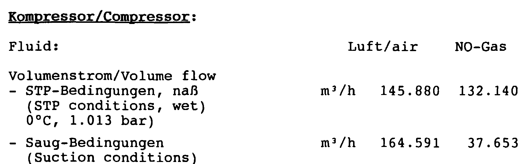
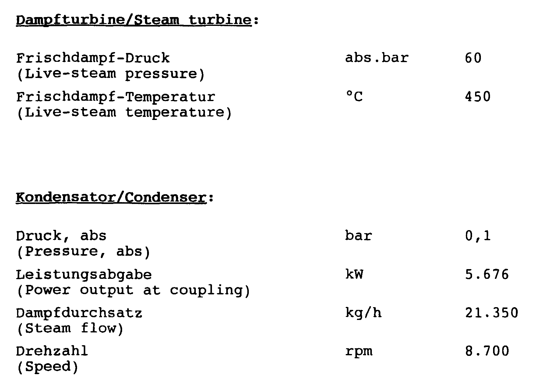
Als Beispiel für einen möglichen einzusetzenden Maschinensatz seien folgende Angaben gemacht, wobei eine Salpetersäure-Anlage nach dem hier beschriebenen Zwei-Druckverfahren zugrundegelegt wird mit 900 Tagestonnen Salpetersäure bezogen auf eine 100 %-ige Konzentration. Die Beispiele beziehen sich auf einen Mehrwellen-Getriebe-Turboverdichter der beschriebenen Art:As an example of a possible machine set to be used the following information is given, with a nitric acid plant according to the two-printing process described here the basis is 900 tonnes of nitric acid per day based on a 100% concentration. The examples refer to a multi-shaft geared turbo compressor of the type described:

- [1][1]
- J. Pruemper, Moderne vielstufige Getriebekompressoren und ihr Einsatz in der Industrie Konferenz-Einzelbericht: 6. Symposium Pumpen und Verdichter, TU Magdeburg, DDR, 11.-12.4.1989, Band 1 (1989) Apr, Seite 187-201 (15 Seiten, 19 Bilder).J. Pruemper, Modern multi-stage gear compressors and their use in industry Conference single report: 6th Symposium Pumps and Compressors, TU Magdeburg, GDR, April 11-12, 1989, Volume 1 (1989) Apr, page 187-201 (15 pages, 19 images).
- [2][2]
- H.-J. Pruemper, Getriebeverdichter für die Prozeßgasindustrie Zeitschriftenaufsatz: Energieanwendung, Band 42 (1993) Heft 4, Seite 198-200 (3 Seiten, 3 Bilder).H.-J. Pruemper, gear compressor for the process gas industry Journal article: energy application, Volume 42 (1993) Issue 4, pages 198-200 (3 pages, 3 Photos).
- [3][3]
- Uhde GmbH, The Compact Plant, NITROGEN, May-June 1995, p. 32/33.Uhde GmbH, The Compact Plant, NITROGEN, May-June 1995, p. 32/33.
- 11
- NH3-VerdampferNH 3 evaporator
- 22nd
- NH3-Gas-VorwärmerNH 3 gas preheater
- 33rd
- NH3-GasfilterNH 3 gas filter
- 44th
- NH3-LuftmischerNH 3 air mixer
- 55
- LuftfilterAir filter
- 66
- LuftverdichterAir compressor
- 77
- NH3-Brenner mit La Mont-AbhitzekesselNH 3 burner with La Mont waste heat boiler
- 88th
- Restgas-Erhitzer IIResidual gas heater II
- 99
- Nitrose-Gaskühler INitrous gas cooler I
- 1010th
- Nitrose-GaskompressorNitrose gas compressor
- 1111
- Restgas-Erhitzer IResidual gas heater I
- 1212th
- Nitrose-Gaskühler IINitrous gas cooler II
- 1313
- AbsorptionsturmAbsorption tower
- 1414
- HNO3-EntgaserENT 3 degasser
- 1515
- Restgas-Radial-ExpanderResidual gas radial expander
- 1616
- DampftrommelSteam drum
- 1717th
- KondensationsdampfturbineCondensing steam turbine
- 1818th
- Kondensatorcapacitor
- 1919th
- Mehrwellen-Getriebe-TurboverdichterMulti-shaft gear turbo compressor
- 2121
- erste Ritzelwellefirst pinion shaft
- 2222
- zweite Ritzelwellesecond pinion shaft
- 2323
- dritte Ritzelwellethird pinion shaft
- 2424th
- vierte Ritzelwellefourth pinion shaft
- 6161
- Niederdruckstufe des LuftverdichterLow pressure stage of the air compressor
- 6262
- Hochdruckstufe des LuftverdichterHigh pressure stage of the air compressor
- 100100
- NH3-flüssigNH 3 liquid
- 101101
- ProzeßluftProcess air
- 103103
- Salpetersäurenitric acid
- 104104
- ProzeßwasserProcess water
- 105105
- Restgas-SchornsteinResidual gas chimney
- 111111
- Niederdruckstufe des Nitrose-GaskompressorsLow pressure stage of the nitrose gas compressor
- 112112
- Hochdruckstufe des Nitrose-GaskompressorsHigh pressure stage of the nitrose gas compressor
- 151151
- Niederdruckstufe des Restgas-Radial-ExpandersLow pressure stage of the residual gas radial expander
- 152152
- Hochdruckstufe des Restgas-Radial-ExpandersHigh-pressure stage of the residual gas radial expander
Claims (11)
dadurch gekennzeichnet,
daß ein Mehrwellen-Getriebe-Turboverdichter getrennt von Prozeßluft und von Nitrosegas beaufschlagt wird, wobei die Prozeßluft auf den genannten ersten Druck verdichtet und das Nitrosegas auf den genannten zweiten Druck verdichtet wird.Process for the production of nitric acid by the two-pressure process, in which the ammonia used is burned at a first, low pressure by means of compressed process air and the nitrous gas formed by the combustion is at least partially absorbed by water at a second, comparatively higher pressure than the first whereby the nitric acid is formed and the non-absorbed residual gas is expanded from the second pressure to ambient pressure in order to obtain compression work in a residual gas expander,
characterized,
that a multi-shaft geared turbocompressor is charged separately from process air and from nitrous gas, the process air being compressed to said first pressure and the nitrous gas being compressed to said second pressure.
dadurch gekennzeichnet,
daß die vom Restgasexpander erzeugte Verdichterarbeit mindestens teilweise zum Antrieb von Nitrosegas-Verdichterstufen und/oder von Luft-Verdichterstufen des Mehrwellen-Getriebe-Turboverdichters verwendet wird. Method according to claim 1,
characterized,
that the compressor work generated by the residual gas expander is used at least in part to drive nitrous gas compressor stages and / or air compressor stages of the multi-shaft geared turbo compressor.
dadurch gekennzeichnet,
daß die von einem oder mehreren abtriebsseitigen Wellenenden eines Restgasexpanders erzeugte Verdichterarbeit unmittelbar und drehzahlidentisch an mindestens eine Ritzelwelle des einen einzigen Mehrwellen-Getriebe-Turboverdichters übertragen wird.The method of claim 1 or 2,
characterized,
that the compressor work generated by one or more shaft ends of a residual gas expander on the output side is transmitted directly and at identical speed to at least one pinion shaft of the single multi-shaft geared turbocompressor.
dadurch gekennzeichnet,
daß das Großrad des einen einzigen Mehrwellen-Getriebe-Turboverdichters entweder von einem Elektromotor, einem Dieselmotor, oder einer Gas- oder einer Dampfturbine angetrieben wird.Method according to one of the preceding claims,
characterized,
that the large wheel of a single multi-shaft geared turbocompressor is driven either by an electric motor, a diesel engine, or a gas or a steam turbine.
dadurch gekennzeichnet,
daß eine Ritzelwelle des einen einzigen Mehrwellen-Getriebe-Turboverdichters von einer Gas- oder einer Dampfturbine unmittelbar und drehzahlidentisch angetrieben wird.Method according to one of the preceding claims,
characterized,
that a pinion shaft of a single multi-shaft geared turbocompressor is driven directly and identically by a gas or steam turbine.
dadurch gekennzeichnet,
daß aus der Niederdruckstufe des Luftverdichters des Mehrwellen-Getriebe-Turboverdichters die verdichtete Luft ungekühlt in die Hochdruckstufe übergeleitet wird. Method according to one of the preceding claims,
characterized,
that the compressed air is transferred uncooled from the low pressure stage of the air compressor of the multi-shaft geared turbo compressor to the high pressure stage.
dadurch gekennzeichnet,
daß aus der Niederdruckstufe des Nitrosegasverdichters des Mehrwellen-Getriebe-Turboverdichters die verdichteten Nitrosegase ungekühlt in die Hochdruckstufe übergeleitet werden.Method according to one of the preceding claims,
characterized,
that from the low-pressure stage of the nitrous gas compressor of the multi-shaft geared turbocompressor, the compressed nitrous gases are transferred uncooled to the high-pressure stage.
dadurch gekennzeichnet,
daß in der Anlage ein Mehrwellen-Getriebe-Turboverdichter (19) vorgesehen ist mit einem Verdichter zur Verdichtung der Prozeßluft auf den ersten Druck und mit einem Nitrosegasverdichter zur Verdichtung des Nitrosegases auf einen zweiten Druck.Plant for the production of nitric acid by the two-pressure process with an NH 3 burner (7) for burning the ammonia used at a first, low pressure and a compressor for supplying the process air, an adsorption tower (13) for the partial adsorption of the nitrous gas by means of water and removal of the nitric acid with a residual gas expander to obtain compression work and to relax the residual gas from the second pressure level to ambient pressure,
characterized,
that in the system a multi-shaft geared turbocompressor (19) is provided with a compressor for compressing the process air to the first pressure and with a nitrous gas compressor for compressing the nitrous gas to a second pressure.
dadurch gekennzeichnet,
daß der eine einzige Mehrwellen-Getriebe-Turboverdichter (19) mit vier Ritzelwellen (21-24) ausgestattet ist, die erste (21) und die dritte Ritzelwelle (23) in der horizontalen Mittelebene, die durch die Achse des Großrades (25) festgelegt ist, angeordnet sind, die zweite Ritzelwelle (22) zentrisch über dem Großrad (25) und die vierte Ritzelwelle (25) zentrisch unter dem Großrad angeordnet ist (Fig. 2).System according to claim 8,
characterized,
that the one multi-shaft geared turbo-compressor (19) is equipped with four pinion shafts (21-24), the first (21) and the third pinion shaft (23) in the horizontal median plane, which is determined by the axis of the large wheel (25) is arranged, the second pinion shaft (22) is arranged centrally above the large wheel (25) and the fourth pinion shaft (25) centrally below the large wheel (FIG. 2).
dadurch gekennzeichnet,
daß mindestens drei Ritzelwellen zwei Enden mit Laufrädern von Verdichtern bzw. Expandern aufweisen.System according to claim 8 or 9,
characterized,
that at least three pinion shafts have two ends with impellers of compressors or expanders.
dadurch gekennzeichnet,
characterized,
Applications Claiming Priority (2)
| Application Number | Priority Date | Filing Date | Title |
|---|---|---|---|
| DE19813223 | 1998-03-26 | ||
| DE19813223 | 1998-03-26 |
Publications (3)
| Publication Number | Publication Date |
|---|---|
| EP0945400A2 true EP0945400A2 (en) | 1999-09-29 |
| EP0945400A3 EP0945400A3 (en) | 2000-05-17 |
| EP0945400B1 EP0945400B1 (en) | 2002-06-05 |
Family
ID=7862325
Family Applications (1)
| Application Number | Title | Priority Date | Filing Date |
|---|---|---|---|
| EP99105223A Expired - Lifetime EP0945400B1 (en) | 1998-03-26 | 1999-03-13 | Process and plant for the preparation of nitric acid |
Country Status (5)
| Country | Link |
|---|---|
| US (1) | US6264910B1 (en) |
| EP (1) | EP0945400B1 (en) |
| JP (1) | JP4469437B2 (en) |
| DE (1) | DE59901589D1 (en) |
| ES (1) | ES2177162T3 (en) |
Cited By (6)
| Publication number | Priority date | Publication date | Assignee | Title |
|---|---|---|---|---|
| WO2001068520A1 (en) * | 2000-03-10 | 2001-09-20 | Uhde Gmbh | Method for producing nitric acid |
| WO2003070634A1 (en) * | 2002-02-22 | 2003-08-28 | Uhde Gmbh | Method for the production of nitric acid |
| WO2011054928A1 (en) * | 2009-11-06 | 2011-05-12 | Basf Se | Method for producing nitric acid by means of a load-controllable production system |
| CN102502541A (en) * | 2011-10-21 | 2012-06-20 | 天津华景化工新技术开发有限公司 | Production method of high-concentration dilute nitric acid |
| WO2014180688A1 (en) | 2013-05-08 | 2014-11-13 | Voith Patent Gmbh | Transmission and compressor system for a transmission |
| EP4140947A1 (en) * | 2021-08-25 | 2023-03-01 | Yara International ASA | Mono pressure system for producing nitric acid and method of operating thereof |
Families Citing this family (12)
| Publication number | Priority date | Publication date | Assignee | Title |
|---|---|---|---|---|
| DE102008027232B3 (en) * | 2008-06-06 | 2009-09-03 | Uhde Gmbh | Blocking of the NO compressor and the residual gas expander in a nitric acid plant |
| DE202016002126U1 (en) | 2016-04-06 | 2016-04-24 | Man Diesel & Turbo Se | Machine train for the production of nitric acid |
| DE102016003950A1 (en) | 2016-04-06 | 2017-10-12 | Man Diesel & Turbo Se | Machine train for the production of nitric acid |
| DE102017201180A1 (en) * | 2017-01-25 | 2018-07-26 | Thyssenkrupp Ag | Process for the preparation of nitric acid and suitable plant |
| EP3372556A1 (en) * | 2017-03-07 | 2018-09-12 | Casale Sa | A plant for the production of nitric acid, a related process and method of revamping |
| EP4238932A1 (en) * | 2022-03-03 | 2023-09-06 | Yara International ASA | Dual pressure system for producing nitric acid and method of operating thereof |
| EP4209453A1 (en) * | 2022-01-11 | 2023-07-12 | Yara International ASA | Dual pressure system for producing nitric acid and method of operating thereof |
| AU2022334886A1 (en) * | 2021-08-25 | 2023-12-14 | Yara International Asa | Dual pressure system for producing nitric acid and method of operating thereof |
| AU2022334801A1 (en) * | 2021-08-25 | 2023-12-14 | Yara International Asa | Dual pressure system for producing nitric acid and method of operating thereof |
| WO2023152293A1 (en) | 2022-02-11 | 2023-08-17 | Thyssenkrupp Industrial Solutions Ag | Nitric acid plant for producing nitric acid |
| BE1030268B1 (en) | 2022-02-11 | 2023-09-11 | Thyssenkrupp Ag | Nitric acid plant for the production of nitric acid |
| DE102022201476A1 (en) | 2022-02-11 | 2023-08-17 | Thyssenkrupp Ag | Nitric acid plant for the production of nitric acid |
Citations (3)
| Publication number | Priority date | Publication date | Assignee | Title |
|---|---|---|---|---|
| DE4239138A1 (en) * | 1992-11-20 | 1994-05-26 | Bhs Voith Getriebetechnik Gmbh | Multiple arrangement of compressors - has one compressor unit driven by turbine unit separated from transmission system |
| EP0602491A1 (en) * | 1992-12-07 | 1994-06-22 | BHS-Bayerische Berg-, Hütten- und Salzwerke Aktiengesellschaft | Transmission and compressor system |
| EP0440902B1 (en) * | 1990-02-06 | 1994-06-22 | Deutsche Babcock- Borsig Aktiengesellschaft | Transmission and centrifugal compressor |
Family Cites Families (1)
| Publication number | Priority date | Publication date | Assignee | Title |
|---|---|---|---|---|
| DE2856589B1 (en) | 1978-12-29 | 1980-03-27 | Davy Internat Ag | Method and device for the time-limited drive of the turbine (s) coupled with the air and / or the nitrous gas compressor in a plant for the production of nitric acid |
-
1999
- 1999-03-13 DE DE59901589T patent/DE59901589D1/en not_active Expired - Lifetime
- 1999-03-13 ES ES99105223T patent/ES2177162T3/en not_active Expired - Lifetime
- 1999-03-13 EP EP99105223A patent/EP0945400B1/en not_active Expired - Lifetime
- 1999-03-25 JP JP08229499A patent/JP4469437B2/en not_active Expired - Fee Related
-
2001
- 2001-03-26 US US09/277,389 patent/US6264910B1/en not_active Expired - Lifetime
Patent Citations (3)
| Publication number | Priority date | Publication date | Assignee | Title |
|---|---|---|---|---|
| EP0440902B1 (en) * | 1990-02-06 | 1994-06-22 | Deutsche Babcock- Borsig Aktiengesellschaft | Transmission and centrifugal compressor |
| DE4239138A1 (en) * | 1992-11-20 | 1994-05-26 | Bhs Voith Getriebetechnik Gmbh | Multiple arrangement of compressors - has one compressor unit driven by turbine unit separated from transmission system |
| EP0602491A1 (en) * | 1992-12-07 | 1994-06-22 | BHS-Bayerische Berg-, Hütten- und Salzwerke Aktiengesellschaft | Transmission and compressor system |
Non-Patent Citations (2)
| Title |
|---|
| H[NGGELI W. : "EXPANSIONSTURBINEN F]R DIE HERSTELLUNG VON SALPETERSA]RE" TECHNISCHE RUNDSCHAU SULZER, Bd. 2, 1986, Seite 29-31 XP002132897 * |
| UHDE GMBH: "THE COMPACT PLANT" NITROGEN,1995, Seiten 32--33, XP002132898 * |
Cited By (8)
| Publication number | Priority date | Publication date | Assignee | Title |
|---|---|---|---|---|
| WO2001068520A1 (en) * | 2000-03-10 | 2001-09-20 | Uhde Gmbh | Method for producing nitric acid |
| WO2003070634A1 (en) * | 2002-02-22 | 2003-08-28 | Uhde Gmbh | Method for the production of nitric acid |
| US7258849B2 (en) | 2002-02-22 | 2007-08-21 | Uhde Gmbh | Method for the production of nitric acid |
| WO2011054928A1 (en) * | 2009-11-06 | 2011-05-12 | Basf Se | Method for producing nitric acid by means of a load-controllable production system |
| CN102502541A (en) * | 2011-10-21 | 2012-06-20 | 天津华景化工新技术开发有限公司 | Production method of high-concentration dilute nitric acid |
| WO2014180688A1 (en) | 2013-05-08 | 2014-11-13 | Voith Patent Gmbh | Transmission and compressor system for a transmission |
| EP4140947A1 (en) * | 2021-08-25 | 2023-03-01 | Yara International ASA | Mono pressure system for producing nitric acid and method of operating thereof |
| WO2023025871A1 (en) * | 2021-08-25 | 2023-03-02 | Yara International Asa | Mono pressure system for producing nitric acid and method of operating thereof |
Also Published As
| Publication number | Publication date |
|---|---|
| JPH11314907A (en) | 1999-11-16 |
| EP0945400A3 (en) | 2000-05-17 |
| JP4469437B2 (en) | 2010-05-26 |
| US6264910B1 (en) | 2001-07-24 |
| EP0945400B1 (en) | 2002-06-05 |
| ES2177162T3 (en) | 2002-12-01 |
| DE59901589D1 (en) | 2002-07-11 |
Similar Documents
| Publication | Publication Date | Title |
|---|---|---|
| EP0945400B1 (en) | Process and plant for the preparation of nitric acid | |
| EP1726814B1 (en) | Jet engine | |
| EP2569542B1 (en) | Multi-stage integrally geared compressor | |
| DE4416497C1 (en) | Geared multi-shaft turbo-compressor and geared multi-shaft radial expander | |
| DE102008031116B4 (en) | Geared turbomachine for a machine train, machine train with and gear for geared turbomachine | |
| EP2285739B1 (en) | Sealing the no compressor and the residual gas expander in a nitric acid plant | |
| DE69817638T2 (en) | Compression system for a turbomachine | |
| DE102005023161A1 (en) | Preparation of nitric acid comprises combusting ammonia by passing air at low pressure in a compressor, forming nitrogen gas at high pressure and partially introducing water to nitrogen gas | |
| WO2011023690A2 (en) | Compressor | |
| EP2496519B1 (en) | Method for producing nitric acid by means of a load-controllable production system | |
| CH665452A5 (en) | COMBINED GAS / STEAM TURBINE POWER PLANT WITH CO COMBUSTION. | |
| EP4087820B1 (en) | Process and plant for preparing nitric acid | |
| EP2794470B1 (en) | Process and apparatus for preparation of nitric acid | |
| DE2440287A1 (en) | AIR COMPRESSION SYSTEM | |
| DE102016003950A1 (en) | Machine train for the production of nitric acid | |
| DE202016002126U1 (en) | Machine train for the production of nitric acid | |
| DE4239138A1 (en) | Multiple arrangement of compressors - has one compressor unit driven by turbine unit separated from transmission system | |
| DE1813335B2 (en) | Multi-stage turbo compressor | |
| BE1030268B1 (en) | Nitric acid plant for the production of nitric acid | |
| DE102008026025A1 (en) | Drive train for motor vehicle, has exhaust-gas turbine arranged in flow direction of exhaust gas behind fresh air compressor, where direction inflow of compressor corresponds to direction of outflow of another compressor | |
| DE2848030A1 (en) | MULTI-STAGE COMPRESSOR | |
| DE102017124689A1 (en) | Axial compressor, comprising juxtaposed rotors that rotate in opposite directions | |
| DE2241202A1 (en) | GAS TURBINE SYSTEM WITH HEAT EXCHANGER | |
| WO2000077364A1 (en) | Internal combustion engine | |
| DE102022201476A1 (en) | Nitric acid plant for the production of nitric acid |
Legal Events
| Date | Code | Title | Description |
|---|---|---|---|
| PUAI | Public reference made under article 153(3) epc to a published international application that has entered the european phase |
Free format text: ORIGINAL CODE: 0009012 |
|
| AK | Designated contracting states |
Kind code of ref document: A2 Designated state(s): CH DE ES FR GB IT LI NL SE |
|
| AX | Request for extension of the european patent |
Free format text: AL;LT;LV;MK;RO;SI |
|
| RAP1 | Party data changed (applicant data changed or rights of an application transferred) |
Owner name: MAN TURBOMASCHINEN AG GHH BORSIG Owner name: KRUPP UHDE GMBH |
|
| PUAL | Search report despatched |
Free format text: ORIGINAL CODE: 0009013 |
|
| RIC1 | Information provided on ipc code assigned before grant |
Free format text: 7C 01B 21/00 A, 7C 01B 21/28 B |
|
| AK | Designated contracting states |
Kind code of ref document: A3 Designated state(s): AT BE CH CY DE DK ES FI FR GB GR IE IT LI LU MC NL PT SE |
|
| AX | Request for extension of the european patent |
Free format text: AL;LT;LV;MK;RO;SI |
|
| 17P | Request for examination filed |
Effective date: 20000811 |
|
| AKX | Designation fees paid |
Free format text: CH DE ES FR GB IT LI NL SE |
|
| GRAG | Despatch of communication of intention to grant |
Free format text: ORIGINAL CODE: EPIDOS AGRA |
|
| GRAG | Despatch of communication of intention to grant |
Free format text: ORIGINAL CODE: EPIDOS AGRA |
|
| GRAH | Despatch of communication of intention to grant a patent |
Free format text: ORIGINAL CODE: EPIDOS IGRA |
|
| RTI1 | Title (correction) |
Free format text: PROCESS AND PLANT FOR THE PREPARATION OF NITRIC ACID |
|
| 17Q | First examination report despatched |
Effective date: 20010907 |
|
| GRAH | Despatch of communication of intention to grant a patent |
Free format text: ORIGINAL CODE: EPIDOS IGRA |
|
| GRAA | (expected) grant |
Free format text: ORIGINAL CODE: 0009210 |
|
| AK | Designated contracting states |
Kind code of ref document: B1 Designated state(s): CH DE ES FR GB IT LI NL SE |
|
| REG | Reference to a national code |
Ref country code: GB Ref legal event code: FG4D Free format text: NOT ENGLISH |
|
| REG | Reference to a national code |
Ref country code: CH Ref legal event code: EP |
|
| REF | Corresponds to: |
Ref document number: 59901589 Country of ref document: DE Date of ref document: 20020711 |
|
| GBT | Gb: translation of ep patent filed (gb section 77(6)(a)/1977) |
Effective date: 20020705 |
|
| ET | Fr: translation filed | ||
| REG | Reference to a national code |
Ref country code: CH Ref legal event code: PFA Free format text: MAN TURBOMASCHINEN AG GHH BORSIG;KRUPP UHDE GMBH TRANSFER- MAN TURBOMASCHINEN AG GHH BORSIG;UHDE GMBH * MAN TURBOMASCHINEN AG GHH BORSIG,BAHNHOFSTRASSE 66,46145 OBERHAUSEN (DE);UHDE GMBH,FRIEDRICH-UHDE-STRASSE 15,44141 DORTMUND (DE) TRANSFER- MAN TURBOMASCHINEN AG GHH BORSIG,STEINBRINKSTRASSE 1,46145 OBERHAUSEN (DE);UHDE GMBH,FRIEDRICH-UHDE-STRASSE 15,44141 DORTMUND (DE) Ref country code: CH Ref legal event code: NV Representative=s name: BOVARD AG PATENTANWAELTE |
|
| RAP2 | Party data changed (patent owner data changed or rights of a patent transferred) |
Owner name: MAN TURBOMASCHINEN AG GHH BORSIG Owner name: UHDE GMBH |
|
| REG | Reference to a national code |
Ref country code: ES Ref legal event code: FG2A Ref document number: 2177162 Country of ref document: ES Kind code of ref document: T3 |
|
| NLT1 | Nl: modifications of names registered in virtue of documents presented to the patent office pursuant to art. 16 a, paragraph 1 |
Owner name: MAN TURBOMASCHINEN AG GHH BORSIG;UHDE GMBH |
|
| NLT2 | Nl: modifications (of names), taken from the european patent patent bulletin |
Owner name: UHDE GMBH EN MAN TURBOMASCHINEN AG GHH BORSIG |
|
| PLBE | No opposition filed within time limit |
Free format text: ORIGINAL CODE: 0009261 |
|
| STAA | Information on the status of an ep patent application or granted ep patent |
Free format text: STATUS: NO OPPOSITION FILED WITHIN TIME LIMIT |
|
| REG | Reference to a national code |
Ref country code: FR Ref legal event code: CD |
|
| 26N | No opposition filed |
Effective date: 20030306 |
|
| REG | Reference to a national code |
Ref country code: GB Ref legal event code: 732E |
|
| NLS | Nl: assignments of ep-patents |
Owner name: MAN TURBO AG Effective date: 20060621 |
|
| NLT1 | Nl: modifications of names registered in virtue of documents presented to the patent office pursuant to art. 16 a, paragraph 1 |
Owner name: MAN TURBO AG Owner name: UHDE GMBH Owner name: MAN TURBOMASCHINEN AG |
|
| REG | Reference to a national code |
Ref country code: CH Ref legal event code: PUEA Owner name: UHDE GMBH Free format text: UHDE GMBH#FRIEDRICH-UHDE-STRASSE 15#44141 DORTMUND (DE) $ MAN DIESEL & TURBO SE#STADTBACHSTRASSE 1#86153 AUGSBURG (DE) -TRANSFER TO- UHDE GMBH#FRIEDRICH-UHDE-STRASSE 15#44141 DORTMUND (DE) Ref country code: CH Ref legal event code: PFA Owner name: UHDE GMBH Free format text: MAN TURBOMASCHINEN AG GHH BORSIG#STEINBRINKSTRASSE 1#46145 OBERHAUSEN (DE) $ UHDE GMBH#FRIEDRICH-UHDE-STRASSE 15#44141 DORTMUND (DE) -TRANSFER TO- UHDE GMBH#FRIEDRICH-UHDE-STRASSE 15#44141 DORTMUND (DE) $ MAN DIESEL & TURBO SE#STADTBACHSTRASSE 1#86153 AUGSBURG (DE) |
|
| REG | Reference to a national code |
Ref country code: CH Ref legal event code: PFA Owner name: UHDE GMBH Free format text: UHDE GMBH#FRIEDRICH-UHDE-STRASSE 15#44141 DORTMUND (DE) -TRANSFER TO- UHDE GMBH#FRIEDRICH-UHDE-STRASSE 15#44141 DORTMUND (DE) |
|
| REG | Reference to a national code |
Ref country code: ES Ref legal event code: PC2A Owner name: UHDE GMBH Effective date: 20110607 |
|
| REG | Reference to a national code |
Ref country code: DE Ref legal event code: R082 Ref document number: 59901589 Country of ref document: DE Representative=s name: KUTZENBERGER WOLFF & PARTNER PATENTANWALTSPART, DE Effective date: 20120426 Ref country code: DE Ref legal event code: R081 Ref document number: 59901589 Country of ref document: DE Owner name: THYSSENKRUPP INDUSTRIAL SOLUTIONS AG, DE Free format text: FORMER OWNERS: KRUPP UHDE GMBH, 44141 DORTMUND, DE; MAN TURBOMASCHINEN AG GHH BORSIG, 46145 OBERHAUSEN, DE Effective date: 20120426 Ref country code: DE Ref legal event code: R081 Ref document number: 59901589 Country of ref document: DE Owner name: THYSSENKRUPP UHDE GMBH, DE Free format text: FORMER OWNERS: KRUPP UHDE GMBH, 44141 DORTMUND, DE; MAN TURBOMASCHINEN AG GHH BORSIG, 46145 OBERHAUSEN, DE Effective date: 20120426 Ref country code: DE Ref legal event code: R081 Ref document number: 59901589 Country of ref document: DE Owner name: MAN DIESEL & TURBO SE, DE Free format text: FORMER OWNERS: KRUPP UHDE GMBH, 44141 DORTMUND, DE; MAN TURBOMASCHINEN AG GHH BORSIG, 46145 OBERHAUSEN, DE Effective date: 20120426 Ref country code: DE Ref legal event code: R081 Ref document number: 59901589 Country of ref document: DE Owner name: MAN DIESEL & TURBO SE, DE Free format text: FORMER OWNER: KRUPP UHDE GMBH, MAN TURBOMASCHINEN AG GHH BORSI, , DE Effective date: 20120426 Ref country code: DE Ref legal event code: R081 Ref document number: 59901589 Country of ref document: DE Owner name: THYSSENKRUPP UHDE GMBH, DE Free format text: FORMER OWNER: KRUPP UHDE GMBH, MAN TURBOMASCHINEN AG GHH BORSI, , DE Effective date: 20120426 |
|
| REG | Reference to a national code |
Ref country code: FR Ref legal event code: CD Owner name: MAN DIESEL & TURBO SE Effective date: 20120613 |
|
| REG | Reference to a national code |
Ref country code: GB Ref legal event code: 732E Free format text: REGISTERED BETWEEN 20121101 AND 20121107 |
|
| REG | Reference to a national code |
Ref country code: DE Ref legal event code: R082 Ref document number: 59901589 Country of ref document: DE Representative=s name: KUTZENBERGER WOLFF & PARTNER PATENTANWALTSPART, DE |
|
| REG | Reference to a national code |
Ref country code: FR Ref legal event code: PLFP Year of fee payment: 17 |
|
| REG | Reference to a national code |
Ref country code: DE Ref legal event code: R082 Ref document number: 59901589 Country of ref document: DE Representative=s name: KUTZENBERGER WOLFF & PARTNER PATENTANWALTSPART, DE Ref country code: DE Ref legal event code: R081 Ref document number: 59901589 Country of ref document: DE Owner name: THYSSENKRUPP INDUSTRIAL SOLUTIONS AG, DE Free format text: FORMER OWNERS: MAN DIESEL & TURBO SE, 86153 AUGSBURG, DE; THYSSENKRUPP UHDE GMBH, 44141 DORTMUND, DE Ref country code: DE Ref legal event code: R081 Ref document number: 59901589 Country of ref document: DE Owner name: MAN DIESEL & TURBO SE, DE Free format text: FORMER OWNERS: MAN DIESEL & TURBO SE, 86153 AUGSBURG, DE; THYSSENKRUPP UHDE GMBH, 44141 DORTMUND, DE |
|
| REG | Reference to a national code |
Ref country code: FR Ref legal event code: PLFP Year of fee payment: 18 |
|
| REG | Reference to a national code |
Ref country code: FR Ref legal event code: PLFP Year of fee payment: 19 |
|
| PGFP | Annual fee paid to national office [announced via postgrant information from national office to epo] |
Ref country code: DE Payment date: 20170322 Year of fee payment: 19 Ref country code: SE Payment date: 20170321 Year of fee payment: 19 Ref country code: NL Payment date: 20170321 Year of fee payment: 19 Ref country code: CH Payment date: 20170322 Year of fee payment: 19 Ref country code: FR Payment date: 20170322 Year of fee payment: 19 |
|
| PGFP | Annual fee paid to national office [announced via postgrant information from national office to epo] |
Ref country code: GB Payment date: 20170322 Year of fee payment: 19 |
|
| PGFP | Annual fee paid to national office [announced via postgrant information from national office to epo] |
Ref country code: ES Payment date: 20170315 Year of fee payment: 19 |
|
| PGFP | Annual fee paid to national office [announced via postgrant information from national office to epo] |
Ref country code: IT Payment date: 20170323 Year of fee payment: 19 |
|
| REG | Reference to a national code |
Ref country code: DE Ref legal event code: R119 Ref document number: 59901589 Country of ref document: DE |
|
| PG25 | Lapsed in a contracting state [announced via postgrant information from national office to epo] |
Ref country code: SE Free format text: LAPSE BECAUSE OF NON-PAYMENT OF DUE FEES Effective date: 20180314 |
|
| REG | Reference to a national code |
Ref country code: CH Ref legal event code: PL |
|
| REG | Reference to a national code |
Ref country code: NL Ref legal event code: MM Effective date: 20180401 |
|
| GBPC | Gb: european patent ceased through non-payment of renewal fee |
Effective date: 20180313 |
|
| PG25 | Lapsed in a contracting state [announced via postgrant information from national office to epo] |
Ref country code: NL Free format text: LAPSE BECAUSE OF NON-PAYMENT OF DUE FEES Effective date: 20180401 |
|
| PG25 | Lapsed in a contracting state [announced via postgrant information from national office to epo] |
Ref country code: DE Free format text: LAPSE BECAUSE OF NON-PAYMENT OF DUE FEES Effective date: 20181002 |
|
| PG25 | Lapsed in a contracting state [announced via postgrant information from national office to epo] |
Ref country code: GB Free format text: LAPSE BECAUSE OF NON-PAYMENT OF DUE FEES Effective date: 20180313 Ref country code: LI Free format text: LAPSE BECAUSE OF NON-PAYMENT OF DUE FEES Effective date: 20180331 Ref country code: CH Free format text: LAPSE BECAUSE OF NON-PAYMENT OF DUE FEES Effective date: 20180331 Ref country code: IT Free format text: LAPSE BECAUSE OF NON-PAYMENT OF DUE FEES Effective date: 20180313 |
|
| PG25 | Lapsed in a contracting state [announced via postgrant information from national office to epo] |
Ref country code: FR Free format text: LAPSE BECAUSE OF NON-PAYMENT OF DUE FEES Effective date: 20180331 |
|
| REG | Reference to a national code |
Ref country code: ES Ref legal event code: FD2A Effective date: 20190904 |
|
| PG25 | Lapsed in a contracting state [announced via postgrant information from national office to epo] |
Ref country code: ES Free format text: LAPSE BECAUSE OF NON-PAYMENT OF DUE FEES Effective date: 20180314 |