EP0944522B1 - Hovering aircraft - Google Patents
Hovering aircraft Download PDFInfo
- Publication number
- EP0944522B1 EP0944522B1 EP97954630A EP97954630A EP0944522B1 EP 0944522 B1 EP0944522 B1 EP 0944522B1 EP 97954630 A EP97954630 A EP 97954630A EP 97954630 A EP97954630 A EP 97954630A EP 0944522 B1 EP0944522 B1 EP 0944522B1
- Authority
- EP
- European Patent Office
- Prior art keywords
- blades
- blade
- vertical axis
- tips
- hovering aircraft
- Prior art date
- Legal status (The legal status is an assumption and is not a legal conclusion. Google has not performed a legal analysis and makes no representation as to the accuracy of the status listed.)
- Expired - Lifetime
Links
Images


Classifications
-
- B—PERFORMING OPERATIONS; TRANSPORTING
- B64—AIRCRAFT; AVIATION; COSMONAUTICS
- B64B—LIGHTER-THAN AIR AIRCRAFT
- B64B1/00—Lighter-than-air aircraft
- B64B1/06—Rigid airships; Semi-rigid airships
- B64B1/24—Arrangement of propulsion plant
- B64B1/30—Arrangement of propellers
- B64B1/32—Arrangement of propellers surrounding hull
Definitions
- This invention relates to specialized aircraft having a hovering capability, and particularly to aircraft deriving at least part of their lift through the rotation of airfoils about a generally vertical axis.
- a composite aircraft for aerial logging is known from Document US4482110.
- a semi-buoyant composite aircraft for aerial logging is described in U.S. Patent 5,082,205.
- the semi-buoyant aircraft comprises a large non-rotating balloon surrounded by a rotatable frame carrying propellers, and adjustable horizontal and vertical airfoils.
- a non-buoyant airborne Station Keeping Optical Observation Platform also has been proposed as an aircraft having the capabilities of efficient hovering and precision station keeping.
- the SKOOP combines a conventional helicopter type main rotor with vertical airfoil surfaces mounted at the tip of each main rotor blade for direct force control in the horizontal plane to provide precision positioning capability, which cannot be achieved easily by a conventional helicopter.
- a disadvantage of the hybrid aerial logging aircraft, and of the SKOOP, is that the vertical surfaces, along with the required bracing cables, substantially increase the aircraft's profile power losses.
- This invention addresses the foregoing problems by an aircraft which combines two main rotors, preferably with one coned and the other drooped, positioned one above the other and joined at a radial station.
- This configuration provides a hovering aircraft with efficient direct horizontal and vertical force control without necessitating large pitch and roll attitude changes as with helicopters.
- VectoRotor For convenience, the invention will be referred to by the term "VectoRotor.”
- the VectoRotor can be visualized in either of two ways.
- the two rotors are positioned one above the other with upper and lower blades joined at a location spaced radially from the axis of rotation.
- the concept does not entail a specified number of blades except that the number of blades should be the same for the upper and lower rotors.
- the VectoRotor can be viewed as composed of blade pairs.
- Each blade pair consists of an upper and a lower blade, each with a certain cone or droop angle, located vertically above one another and joined at a radial station.
- the VectoRotor consists of at least two blade pairs and preferably at least three.
- FIGs. 1 and 2 show an aircraft having three blade pairs 10, 12 and 14 mounted for rotation about a central vertical support 16, which may be attached to a cab (not shown) as in the case of Patent 5,082,205, the disclosure of which is incorporated by reference.
- Blade pair 10 comprises an upper blade 18 and a lower blade 20, having a thrust-producing propeller 22 on a motor 24 mounted on a strut 26 between the blades at a location radially spaced from the central support but inboard from the blade tips.
- a thrust-producing propeller 22 on a motor 24 mounted on a strut 26 between the blades at a location radially spaced from the central support but inboard from the blade tips.
- Each of the other blade pairs has a similar propeller.
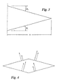
- the VectoRotor was symmetric about a horizontal axis with upper and lower blades joined at the tips as in FIG. 3.
- the lower blade is coned through an angle ⁇ L and the upper blade is drooped through an angle ⁇ U , which is negative since the blade is drooped) .
- ⁇ U - ⁇ L
- the blades are joined at the tips, and the blades are directly above one another.
- none of these three conditions is essential to the VectoRotor's production of direct force in the horizontal plane.
- changes in these three aspects can provide advantages in performance and structural design. These changes are discussed below.
- All of the blades have adjustable lift which can be achieved, for example, by blade pitch adjustment, or by incorporating adjustable control surfaces in the blades.
- Cyclic and collective controls similar to those of a conventional helicopter, are provided to control vertical and horizontal thrust as well as roll and pitch moments.
- the specifications of blade airfoil shape and planform are design variables as in the case of a conventional helicopter rotor.
- the power plant can be tip-driven as shown in FIGs. 1 and 2, or powered from the non-rotating support as in a conventional helicopter.
- an anti-torque device such as a helicopter tail rotor is required.
- the blades can be joined at a radial location inboard of the tips while still taking advantage of the bracing provided by the structural triangulation effected by this joining.
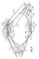
- FIG. 4 is a cross-sectional schematic of the VectoRotor with arrows representing the net aerodynamic force on each blade.
- the dashed arrows show the trimmed case with zero net lateral force and zero net rolling moment.
- Solid arrows show forces modulated to produce a net force to the right while maintaining the same net vertical thrust as in the trimmed case with zero net rolling moment.
- force vectors on the upper and lower rotors are shown as equal.
- differential collective pitch between upper and lower rotors would be used to distribute these forces to produce the required thrust while optimizing performance.
- FIG. 5 is a rear view of one blade pair (half of FIG. 3) where F U and F L are net aerodynamic forces in the x-y plane, r U and r L are radial locations of the blade aerodynamic centers, and h U and h L are the vertical locations of the blade aerodynamic centers. Both ⁇ U and h U have negative values.
- the upper blades are drooped by an amount equal to the amount which the lower blades are coned.
- this is not a requirement, and the angles ⁇ U and ⁇ L can be varied independently, depending upon direct force control requirements, performance and structural considerations.
- FIGs. 6, 7 and 8 are schematics showing three possible alternative arrangements.
- both blades are coned ( ⁇ U and ⁇ L are both positive but not equal).
- the upper blades of the VectoRotor are not required to be located directly above the lower blades. Instead, some performance advantages may be realized by constructing the VectoRotor with fore and aft spacing of its upper and lower blades in a manner analogous to the stagger of the upper and lower wings of a biplane. This would entail a combination of upper and lower blade roots staggered in azimuth with blade sweep.
- the rotor structure is similar to that in FIGS. 1 and 2. However, lift resulting from rotation of the rotors is augmented by the buoyant lift of a large, centrally located, helium-filled cell 28.
- the rotor structure comprises a set of three upper blades 30, 32 and 34, and a set of lower blades, two of which are seen at 36 and 38.
- the blades are supported from a large vertical mast 40 which extends through the helium cell 28.
- the upper and lower sets of blades can be mounted on bearings on the mast so that they can rotate about the mast.
- the blades can be fixed to the mast and the entire mast can rotate in a vertical passage through the helium cell. In the latter case, thrust bearings (not shown) in the vertical passage sustain the vertical forces exerted by the helium cell on mast 40 and vice versa.
- a control cab 42 is mounted at the lower end of the mast 40.
- a rotor (not shown) providing counter-rotating thrust, or another suitable anti-torque device, such as the anti-torque motor described in U.S. Patent 5,082,205, may be provided to prevent the mast, the control cab and the helium cell from rotating with the blades.
- Similar provisions can be made, in the case in which the entire mast rotates, to prevent the control cab and the helium cell from rotating.
- the control cab can be provided with a cargo hoist.
- the blades are connected to the mast 40 through struts shown at 44, 46, 48, 50 and 52, and these struts are rigidified by cables 54, 56, 58, 60, 62 and 64.
- Additional struts e.g. struts 66 and 68, are provided to support cables used to hold the blades in the upper set in fixed relationship to one another and also to hold the blades in the lower set in fixed relationship to one another.
- cables 70 and 72 extend from the tip of strut 66 to the engines 74 and 76
- cables 78 and 80 extend from the tip of strut 66 to the outer ends of struts 44 and 48.
- a blade pitch actuator 82 is connected between blade 38 and engine support 84.
- Blade 38 is connected to engine support 84 through a bearing 86 which allows the actuator 82 to adjust the blade's angle of attack.
- the other blades have similar blade pitch actuators. These actuators are used to maintain and control both cyclic and collective pitch of the blades for control of vertical lift, pitch and roll, and for propulsion of the aircraft in any desired direction.
- the separate actuators can be controlled in such a way as to reduce non-first harmonic components of airload, thereby reducing vibrations in the aircraft.
- Fuel may be delivered to the engines from a centrally located fuel tank through the blades.
- the motors can be electric motors or fluid motors receiving electric or fluid power from a centrally located generator or pump.
- the aircraft of FIG. 9 operates on the same principles as the aircraft of FIGs. 1 and 2, except that the aerodynamic lift produced by rotation of the blades is augmented by the buoyant lift of the helium cell.
- the additional lift increases the payload and decreases fuel costs.
- the buoyant lift provides support for the rotor structure while the aircraft is on the ground.
- the rotor structure comprising a coned set of lower blades and a drooped set of upper blades lends itself particularly well to use with a buoyant gas cell.
- the blades of the upper set can have their tips located below the level of the uppermost part of the gas-containing cell, and the blades of the lower set can have their tips located above the level of the lowermost part of the gas-containing cell.
- a large gas cell can be situated between the upper and lower sets of blades without interfering with their rotation, and without seriously impairing their aerodynamic performance.
- the invention is useful for applications such as aerial observation and aerial logging, among others.
Description
- This invention relates to specialized aircraft having a hovering capability, and particularly to aircraft deriving at least part of their lift through the rotation of airfoils about a generally vertical axis.
- A composite aircraft for aerial logging is known from Document US4482110.
- A semi-buoyant composite aircraft for aerial logging is described in U.S. Patent 5,082,205. The semi-buoyant aircraft comprises a large non-rotating balloon surrounded by a rotatable frame carrying propellers, and adjustable horizontal and vertical airfoils. A non-buoyant airborne Station Keeping Optical Observation Platform (SKOOP) also has been proposed as an aircraft having the capabilities of efficient hovering and precision station keeping. The SKOOP combines a conventional helicopter type main rotor with vertical airfoil surfaces mounted at the tip of each main rotor blade for direct force control in the horizontal plane to provide precision positioning capability, which cannot be achieved easily by a conventional helicopter.
- A disadvantage of the hybrid aerial logging aircraft, and of the SKOOP, is that the vertical surfaces, along with the required bracing cables, substantially increase the aircraft's profile power losses.
- This invention addresses the foregoing problems by an aircraft which combines two main rotors, preferably with one coned and the other drooped, positioned one above the other and joined at a radial station. This configuration provides a hovering aircraft with efficient direct horizontal and vertical force control without necessitating large pitch and roll attitude changes as with helicopters.
-
- FIG. 1 is a top plan view of a hovering aircraft in accordance with the invention;
- FIG. 2 is a fragmentary elevational view thereof;
- FIGs. 3-8 are diagrams illustrating the operation of the aircraft; and
- FIG. 9 is a perspective view of a semi-buoyant aircraft in accordance with the invention.
-
- For convenience, the invention will be referred to by the term "VectoRotor." The VectoRotor can be visualized in either of two ways.
- First, it can be viewed as two helicopter rotors, each with its blades fixed at some coned or drooped position. (Coning or drooping describes a condition in which all blades are positioned with their tips an equal amount above (coned) or below (drooped) the blade roots.) The two rotors are positioned one above the other with upper and lower blades joined at a location spaced radially from the axis of rotation. As with a conventional helicopter rotor, the concept does not entail a specified number of blades except that the number of blades should be the same for the upper and lower rotors. Alternatively, the VectoRotor can be viewed as composed of blade pairs. Each blade pair consists of an upper and a lower blade, each with a certain cone or droop angle, located vertically above one another and joined at a radial station. The VectoRotor consists of at least two blade pairs and preferably at least three.
- FIGs. 1 and 2 show an aircraft having three
blade pairs vertical support 16, which may be attached to a cab (not shown) as in the case of Patent 5,082,205, the disclosure of which is incorporated by reference. -
Blade pair 10 comprises anupper blade 18 and alower blade 20, having a thrust-producingpropeller 22 on amotor 24 mounted on astrut 26 between the blades at a location radially spaced from the central support but inboard from the blade tips. Each of the other blade pairs has a similar propeller. - In its original conception, the VectoRotor was symmetric about a horizontal axis with upper and lower blades joined at the tips as in FIG. 3. The lower blade is coned through an angle βL and the upper blade is drooped through an angle βU, which is negative since the blade is drooped) . In FIG. 3, βU = -βL, the blades are joined at the tips, and the blades are directly above one another. However, none of these three conditions is essential to the VectoRotor's production of direct force in the horizontal plane. In fact, changes in these three aspects can provide advantages in performance and structural design. These changes are discussed below.
- All of the blades have adjustable lift which can be achieved, for example, by blade pitch adjustment, or by incorporating adjustable control surfaces in the blades. Cyclic and collective controls, similar to those of a conventional helicopter, are provided to control vertical and horizontal thrust as well as roll and pitch moments.
- The specifications of blade airfoil shape and planform are design variables as in the case of a conventional helicopter rotor. The power plant can be tip-driven as shown in FIGs. 1 and 2, or powered from the non-rotating support as in a conventional helicopter. Especially in the latter configuration, an anti-torque device such as a helicopter tail rotor is required. The blades can be joined at a radial location inboard of the tips while still taking advantage of the bracing provided by the structural triangulation effected by this joining.
- FIG. 4 is a cross-sectional schematic of the VectoRotor with arrows representing the net aerodynamic force on each blade. The dashed arrows show the trimmed case with zero net lateral force and zero net rolling moment. Solid arrows show forces modulated to produce a net force to the right while maintaining the same net vertical thrust as in the trimmed case with zero net rolling moment. In the trim case, force vectors on the upper and lower rotors are shown as equal. In actuality, differential collective pitch between upper and lower rotors would be used to distribute these forces to produce the required thrust while optimizing performance.
- FIG. 5 is a rear view of one blade pair (half of FIG. 3) where FU and FL are net aerodynamic forces in the x-y plane, rU and rL are radial locations of the blade aerodynamic centers, and hU and hL are the vertical locations of the blade aerodynamic centers. Both βU and hU have negative values. The equations for vertical force, lateral force and roll moment are:
- In the case where βU = -βL., hU = -hL and rU = rL., these equations become:
- In FIGs. 1-5, the upper blades are drooped by an amount equal to the amount which the lower blades are coned. However, this is not a requirement, and the angles βU and βL can be varied independently, depending upon direct force control requirements, performance and structural considerations.
- FIGs. 6, 7 and 8 are schematics showing three possible alternative arrangements. In FIG. 6 the lower blade is not coned. (βL = 0°). In FIG. 7, the upper blade has no droop (βU = 0°). In FIG. 8, both blades are coned (βU and βL are both positive but not equal).
- One consideration in choosing βU and βL is structural design. For the case of a coned rotor blade, flapping moments due to aerodynamic force work to offset flapping moments due to centrifugal force, which eases structural requirements. The opposite is true with a drooped blade. Thus configurations similar to FIG. 7 or 8 would have distinct advantages in this respect over configurations such as that of FIG. 6.
- In forward flight of an aircraft having a VectoRotor configuration with blades joined at the tips as shown in FIG. 3 spanwise flow will produce undesirable aerodynamic effects. By appropriate vertical spacing of the blade roots, the tips of the blades can be spaced as shown in FIG. 1. This requires additional structural stiffening, e.g. by vertical struts, which would increase profile power. However, even with the additional structure, the VectoRotor would still possess considerably lower profile power than known alternative configurations.
- The upper blades of the VectoRotor are not required to be located directly above the lower blades. Instead, some performance advantages may be realized by constructing the VectoRotor with fore and aft spacing of its upper and lower blades in a manner analogous to the stagger of the upper and lower wings of a biplane. This would entail a combination of upper and lower blade roots staggered in azimuth with blade sweep.
- In the semi-buoyant version of the hovering aircraft, as shown in FIG. 9, the rotor structure is similar to that in FIGS. 1 and 2. However, lift resulting from rotation of the rotors is augmented by the buoyant lift of a large, centrally located, helium-filled
cell 28. - The rotor structure comprises a set of three
upper blades vertical mast 40 which extends through thehelium cell 28. The upper and lower sets of blades can be mounted on bearings on the mast so that they can rotate about the mast. Alternatively, the blades can be fixed to the mast and the entire mast can rotate in a vertical passage through the helium cell. In the latter case, thrust bearings (not shown) in the vertical passage sustain the vertical forces exerted by the helium cell onmast 40 and vice versa. - A
control cab 42 is mounted at the lower end of themast 40. In the case in which the blade assemblies rotate relative to the mast and the control cab is fixed to the mast, a rotor (not shown) providing counter-rotating thrust, or another suitable anti-torque device, such as the anti-torque motor described in U.S. Patent 5,082,205, may be provided to prevent the mast, the control cab and the helium cell from rotating with the blades. Similar provisions can be made, in the case in which the entire mast rotates, to prevent the control cab and the helium cell from rotating. The control cab can be provided with a cargo hoist. - The blades are connected to the
mast 40 through struts shown at 44, 46, 48, 50 and 52, and these struts are rigidified bycables example cables strut 66 to theengines cables strut 66 to the outer ends ofstruts - A
blade pitch actuator 82 is connected betweenblade 38 andengine support 84.Blade 38 is connected toengine support 84 through abearing 86 which allows theactuator 82 to adjust the blade's angle of attack. The other blades have similar blade pitch actuators. These actuators are used to maintain and control both cyclic and collective pitch of the blades for control of vertical lift, pitch and roll, and for propulsion of the aircraft in any desired direction. The separate actuators can be controlled in such a way as to reduce non-first harmonic components of airload, thereby reducing vibrations in the aircraft. - Fuel may be delivered to the engines from a centrally located fuel tank through the blades. Alternatively, the motors can be electric motors or fluid motors receiving electric or fluid power from a centrally located generator or pump.
- The aircraft of FIG. 9 operates on the same principles as the aircraft of FIGs. 1 and 2, except that the aerodynamic lift produced by rotation of the blades is augmented by the buoyant lift of the helium cell. The additional lift increases the payload and decreases fuel costs. Moreover, the buoyant lift provides support for the rotor structure while the aircraft is on the ground.
- The rotor structure comprising a coned set of lower blades and a drooped set of upper blades lends itself particularly well to use with a buoyant gas cell. The blades of the upper set can have their tips located below the level of the uppermost part of the gas-containing cell, and the blades of the lower set can have their tips located above the level of the lowermost part of the gas-containing cell. A large gas cell can be situated between the upper and lower sets of blades without interfering with their rotation, and without seriously impairing their aerodynamic performance.
- The invention is useful for applications such as aerial observation and aerial logging, among others.
Claims (9)
- A hovering aircraft having an airfoil blade structure rotatable about a vertical axis, the blade structure comprising a set of upper blades (30, 32, 34) and a set of lower blades (36, 38), all having variable lift, each of said blades having a root and a tip, the root and tip moving substantially in horizontal circles about said vertical axis as the blade structure rotates, the root of each blade being closer than the tip to said vertical axis, and the upper blades converging toward the lower blades from root to tip, so that the vertical spacing between the roots of the upper and lower blades is greater than the vertical spacing between the tips of the upper and lower blades.
- A hovering aircraft having an airfoil blade structure rotatable about a vertical axis, the blade structure comprising a set of upper blades (30, 32, 34) and a set of lower blades (36, 38), all having variable lift, the upper blades converging toward the lower blades from root to tip, and also having interconnecting means (84) for connecting each upper blade with a lower blade, the interconnecting means being at a location spaced inwardly toward said vertical axis from the tips of the upper and lower blades which it interconnects.
- A hovering aircraft according to claim 2, in which the interconnecting means (84) maintains the tips of the upper and lower blades which it interconnects at a sufficient spacing from each other to reduce interference effects.
- A hovering aircraft according to claim 1 having a cell (28) containing a lighter-than-air gas located between the upper and lower sets of blades.
- A hovering aircraft having a support (40) extending along a vertical axis, an airfoil blade structure rotatable about said vertical axis, the blade structure comprising a set of upper blades (30, 32, 34), each upper blade extending outwardly from said vertical axis and being connected to said support, and a set of lower blades (36, 38), each lower blade also extending outwardly from said vertical axis and being connected to said support, all the blades of the upper and lower sets having variable lift, and the upper blades converging toward the lower blades from root to tip.
- A hovering aircraft according to claim 5 having interconnecting means (84) for connecting each upper blade with a lower blade, the interconnecting means being at a location spaced inwardly toward said vertical axis from the tips of the upper and lower blades which it interconnects.
- A hovering aircraft according to claim 5 having interconnecting means (84) for connecting each upper blade with a lower blade, the interconnecting means being at a location spaced inwardly toward said vertical axis from the tips of the upper and lower blades which it interconnects, and maintaining the tips of the upper and lower blades which it interconnects at a sufficient spacing from each other to reduce interference effects.
- A hovering aircraft according to claim 5 having a cell (28) containing a lighter-than-air gas located between the upper and lower sets of blades.
- A hovering aircraft according to claim 5 in which the blades (30, 32, 34) of the upper set are drooping blades and in which the blades (36, 38) of the lower set are coned blades, and having a cell (28) containing a lighter-than-air gas located between the upper and lower sets of blades, the blades of the upper set having tips located below the level of the uppermost part of the gas-containing cell, and the blades of the lower set having tips located above the level of the lowermost part of the gas-containing cell.
Applications Claiming Priority (5)
| Application Number | Priority Date | Filing Date | Title |
|---|---|---|---|
| US3238396P | 1996-12-19 | 1996-12-19 | |
| US32383P | 1996-12-19 | ||
| US08/991,560 US5931411A (en) | 1996-12-19 | 1997-12-16 | Hovering aircraft |
| US991560 | 1997-12-16 | ||
| PCT/US1997/023921 WO1998026980A2 (en) | 1996-12-19 | 1997-12-17 | Hovering aircraft |
Publications (3)
| Publication Number | Publication Date |
|---|---|
| EP0944522A2 EP0944522A2 (en) | 1999-09-29 |
| EP0944522A4 EP0944522A4 (en) | 2000-05-24 |
| EP0944522B1 true EP0944522B1 (en) | 2003-03-12 |
Family
ID=26708345
Family Applications (1)
| Application Number | Title | Priority Date | Filing Date |
|---|---|---|---|
| EP97954630A Expired - Lifetime EP0944522B1 (en) | 1996-12-19 | 1997-12-17 | Hovering aircraft |
Country Status (7)
| Country | Link |
|---|---|
| US (1) | US5931411A (en) |
| EP (1) | EP0944522B1 (en) |
| JP (1) | JP3813992B2 (en) |
| BR (1) | BR9713964A (en) |
| CA (1) | CA2272413C (en) |
| DE (1) | DE69719794T2 (en) |
| WO (1) | WO1998026980A2 (en) |
Families Citing this family (8)
| Publication number | Priority date | Publication date | Assignee | Title |
|---|---|---|---|---|
| WO2004074091A2 (en) * | 2003-02-24 | 2004-09-02 | Charles Raymond Luffman | Air vehicle |
| CA2557893A1 (en) * | 2006-08-29 | 2008-02-29 | Skyhook International Inc. | Hybrid lift air vehicle |
| US7905447B2 (en) * | 2007-11-16 | 2011-03-15 | Lockheed Martin Corporation | System, method and apparatus for aircraft having counter-rotating, ring-winged rotors |
| CN103332294B (en) * | 2013-07-03 | 2016-04-20 | 济南弘毅格致科贸有限公司 | A kind of lifting airscrew |
| JP2019006361A (en) * | 2017-06-28 | 2019-01-17 | 嘉幸 小林 | Buoyancy adjuster and drone with gas-closed vessel |
| CN109649646A (en) * | 2018-09-19 | 2019-04-19 | 徐成栋 | A kind of 3-D Dynamic aircraft |
| RU204528U1 (en) * | 2020-11-25 | 2021-05-28 | Михаил Зеликович Боярер | Jet rotary carrier-thrust propeller of high-speed wingless short take-off and landing aircraft |
| CN114476043A (en) * | 2021-12-31 | 2022-05-13 | 中国航天空气动力技术研究院 | Electronic distributing type rotor unmanned transport plane |
Family Cites Families (6)
| Publication number | Priority date | Publication date | Assignee | Title |
|---|---|---|---|---|
| US1419962A (en) * | 1920-11-06 | 1922-06-20 | Denham William Leslie | Aeroplane |
| US2389798A (en) * | 1943-01-13 | 1945-11-27 | David W Main | Pitch control device for rotor blades |
| US2717131A (en) * | 1954-05-06 | 1955-09-06 | Roger M Barrett | Aircraft with fixed and rotary wings |
| US3976265A (en) * | 1973-05-07 | 1976-08-24 | All American Industries, Inc. | Semibuoyant composite aircraft |
| ZA792253B (en) * | 1978-05-30 | 1980-05-28 | A Crimmins | A composite aircraft |
| US5082205A (en) * | 1990-08-09 | 1992-01-21 | Caufman Robert L | Semi-buoyant composite aircraft with non-rotating aerostat |
-
1997
- 1997-12-16 US US08/991,560 patent/US5931411A/en not_active Expired - Lifetime
- 1997-12-17 CA CA002272413A patent/CA2272413C/en not_active Expired - Fee Related
- 1997-12-17 JP JP52803998A patent/JP3813992B2/en not_active Expired - Fee Related
- 1997-12-17 EP EP97954630A patent/EP0944522B1/en not_active Expired - Lifetime
- 1997-12-17 BR BR9713964-5A patent/BR9713964A/en not_active IP Right Cessation
- 1997-12-17 WO PCT/US1997/023921 patent/WO1998026980A2/en active IP Right Grant
- 1997-12-17 DE DE69719794T patent/DE69719794T2/en not_active Expired - Lifetime
Also Published As
| Publication number | Publication date |
|---|---|
| EP0944522A4 (en) | 2000-05-24 |
| EP0944522A2 (en) | 1999-09-29 |
| WO1998026980A3 (en) | 1999-02-25 |
| DE69719794D1 (en) | 2003-04-17 |
| CA2272413A1 (en) | 1998-06-25 |
| BR9713964A (en) | 2000-08-08 |
| JP3813992B2 (en) | 2006-08-23 |
| JP2002514149A (en) | 2002-05-14 |
| US5931411A (en) | 1999-08-03 |
| DE69719794T2 (en) | 2003-11-20 |
| WO1998026980A2 (en) | 1998-06-25 |
| WO1998026980B1 (en) | 1999-03-25 |
| CA2272413C (en) | 2004-03-30 |
Similar Documents
| Publication | Publication Date | Title |
|---|---|---|
| US20230192293A1 (en) | Distributed propulsion system | |
| US10301016B1 (en) | Stabilized VTOL flying apparatus and aircraft | |
| US20200108919A1 (en) | Quiet Redundant Rotorcraft | |
| US3350035A (en) | Vtol with cylindrical wing | |
| EP2265495B1 (en) | Coaxial rotor aircraft | |
| US4482110A (en) | Cyclorotor composite aircraft | |
| EP3483064B1 (en) | Tilting proprotor with segmented duct | |
| US3976265A (en) | Semibuoyant composite aircraft | |
| US6575401B1 (en) | Vertical-lift and horizontal flight aircraft | |
| EP3243750B1 (en) | Distributed propulsion | |
| US3039719A (en) | Vertical take-off airplane | |
| JP2005502540A (en) | Optimal speed tilt rotor | |
| US5082205A (en) | Semi-buoyant composite aircraft with non-rotating aerostat | |
| WO2018175606A1 (en) | Vertical takeoff and landing aircraft | |
| US11919631B2 (en) | Vertical take-off and landing aircraft with aft rotor tilting | |
| EP0944522B1 (en) | Hovering aircraft | |
| CN111942581B (en) | Distributed lift force duck-type layout vertical take-off and landing unmanned aerial vehicle and control method | |
| CN116101478B (en) | Single-layer variable-pitch structure for miniature coaxial double-oar unmanned aerial vehicle and control method | |
| RU2407675C1 (en) | Tandem-rotor helicopter | |
| EP0619792B1 (en) | Hybrid aircraft | |
| RU2753444C1 (en) | High-speed hybrid coaxial electric helicopter | |
| EP4339109A1 (en) | Vertical takeoff and landing aerial vehicles | |
| CN114802711A (en) | Unmanned aerial vehicle with single duct at tail part |
Legal Events
| Date | Code | Title | Description |
|---|---|---|---|
| PUAI | Public reference made under article 153(3) epc to a published international application that has entered the european phase |
Free format text: ORIGINAL CODE: 0009012 |
|
| 17P | Request for examination filed |
Effective date: 19990709 |
|
| AK | Designated contracting states |
Kind code of ref document: A2 Designated state(s): DE FR GB |
|
| A4 | Supplementary search report drawn up and despatched |
Effective date: 20000410 |
|
| AK | Designated contracting states |
Kind code of ref document: A4 Designated state(s): DE FR GB |
|
| RIC1 | Information provided on ipc code assigned before grant |
Free format text: 7B 64C 27/00 A, 7B 64C 37/02 B, 7B 64B 1/32 B |
|
| GRAH | Despatch of communication of intention to grant a patent |
Free format text: ORIGINAL CODE: EPIDOS IGRA |
|
| GRAH | Despatch of communication of intention to grant a patent |
Free format text: ORIGINAL CODE: EPIDOS IGRA |
|
| GRAA | (expected) grant |
Free format text: ORIGINAL CODE: 0009210 |
|
| AK | Designated contracting states |
Designated state(s): DE FR GB |
|
| REG | Reference to a national code |
Ref country code: GB Ref legal event code: FG4D |
|
| REF | Corresponds to: |
Ref document number: 69719794 Country of ref document: DE Date of ref document: 20030417 Kind code of ref document: P |
|
| ET | Fr: translation filed | ||
| PLBE | No opposition filed within time limit |
Free format text: ORIGINAL CODE: 0009261 |
|
| STAA | Information on the status of an ep patent application or granted ep patent |
Free format text: STATUS: NO OPPOSITION FILED WITHIN TIME LIMIT |
|
| 26N | No opposition filed |
Effective date: 20031215 |
|
| PGFP | Annual fee paid to national office [announced via postgrant information from national office to epo] |
Ref country code: DE Payment date: 20140228 Year of fee payment: 17 |
|
| PGFP | Annual fee paid to national office [announced via postgrant information from national office to epo] |
Ref country code: GB Payment date: 20140325 Year of fee payment: 17 |
|
| PGFP | Annual fee paid to national office [announced via postgrant information from national office to epo] |
Ref country code: FR Payment date: 20140227 Year of fee payment: 17 |
|
| REG | Reference to a national code |
Ref country code: DE Ref legal event code: R119 Ref document number: 69719794 Country of ref document: DE |
|
| GBPC | Gb: european patent ceased through non-payment of renewal fee |
Effective date: 20141217 |
|
| REG | Reference to a national code |
Ref country code: FR Ref legal event code: ST Effective date: 20150831 |
|
| PG25 | Lapsed in a contracting state [announced via postgrant information from national office to epo] |
Ref country code: GB Free format text: LAPSE BECAUSE OF NON-PAYMENT OF DUE FEES Effective date: 20141217 Ref country code: DE Free format text: LAPSE BECAUSE OF NON-PAYMENT OF DUE FEES Effective date: 20150701 |
|
| PG25 | Lapsed in a contracting state [announced via postgrant information from national office to epo] |
Ref country code: FR Free format text: LAPSE BECAUSE OF NON-PAYMENT OF DUE FEES Effective date: 20141231 |