EP0943848A2 - A method of producing a spiral wound gasket and a device for producing the same - Google Patents
A method of producing a spiral wound gasket and a device for producing the same Download PDFInfo
- Publication number
- EP0943848A2 EP0943848A2 EP99104312A EP99104312A EP0943848A2 EP 0943848 A2 EP0943848 A2 EP 0943848A2 EP 99104312 A EP99104312 A EP 99104312A EP 99104312 A EP99104312 A EP 99104312A EP 0943848 A2 EP0943848 A2 EP 0943848A2
- Authority
- EP
- European Patent Office
- Prior art keywords
- hoop material
- checking
- core drum
- stepped
- outer periphery
- Prior art date
- Legal status (The legal status is an assumption and is not a legal conclusion. Google has not performed a legal analysis and makes no representation as to the accuracy of the status listed.)
- Granted
Links
Images


Classifications
-
- F—MECHANICAL ENGINEERING; LIGHTING; HEATING; WEAPONS; BLASTING
- F16—ENGINEERING ELEMENTS AND UNITS; GENERAL MEASURES FOR PRODUCING AND MAINTAINING EFFECTIVE FUNCTIONING OF MACHINES OR INSTALLATIONS; THERMAL INSULATION IN GENERAL
- F16J—PISTONS; CYLINDERS; SEALINGS
- F16J15/00—Sealings
- F16J15/02—Sealings between relatively-stationary surfaces
- F16J15/06—Sealings between relatively-stationary surfaces with solid packing compressed between sealing surfaces
- F16J15/10—Sealings between relatively-stationary surfaces with solid packing compressed between sealing surfaces with non-metallic packing
- F16J15/12—Sealings between relatively-stationary surfaces with solid packing compressed between sealing surfaces with non-metallic packing with metal reinforcement or covering
- F16J15/121—Sealings between relatively-stationary surfaces with solid packing compressed between sealing surfaces with non-metallic packing with metal reinforcement or covering with metal reinforcement
- F16J15/125—Sealings between relatively-stationary surfaces with solid packing compressed between sealing surfaces with non-metallic packing with metal reinforcement or covering with metal reinforcement generally perpendicular to the surfaces
-
- B—PERFORMING OPERATIONS; TRANSPORTING
- B21—MECHANICAL METAL-WORKING WITHOUT ESSENTIALLY REMOVING MATERIAL; PUNCHING METAL
- B21D—WORKING OR PROCESSING OF SHEET METAL OR METAL TUBES, RODS OR PROFILES WITHOUT ESSENTIALLY REMOVING MATERIAL; PUNCHING METAL
- B21D11/00—Bending not restricted to forms of material mentioned in only one of groups B21D5/00, B21D7/00, B21D9/00; Bending not provided for in groups B21D5/00 - B21D9/00; Twisting
- B21D11/06—Bending into helical or spiral form; Forming a succession of return bends, e.g. serpentine form
-
- Y—GENERAL TAGGING OF NEW TECHNOLOGICAL DEVELOPMENTS; GENERAL TAGGING OF CROSS-SECTIONAL TECHNOLOGIES SPANNING OVER SEVERAL SECTIONS OF THE IPC; TECHNICAL SUBJECTS COVERED BY FORMER USPC CROSS-REFERENCE ART COLLECTIONS [XRACs] AND DIGESTS
- Y10—TECHNICAL SUBJECTS COVERED BY FORMER USPC
- Y10T—TECHNICAL SUBJECTS COVERED BY FORMER US CLASSIFICATION
- Y10T29/00—Metal working
- Y10T29/49—Method of mechanical manufacture
- Y10T29/49826—Assembling or joining
- Y10T29/49879—Spaced wall tube or receptacle
Definitions
- the present invention relates to a method of producing a spiral wound gasket for sealing fluid such as liquid including water and oil, and gaseous body including vapor and gas.
- the present invention relates to a device for producing the spiral wound gasket.
- a gasket is disposed between a pair of flanges, the each flange is fastened by a bolt, and the gasket is closely fitted in the each flange, thereby preventing a fluid flowing inside the pipe from leaking to outside.
- the spiral wound gasket is usually employed.
- the spiral wound gasket has a structure wherein a filler material 92 made of a asbestos paper, an expanded graphite tape, a 4-fluorinated ethylene resin tape, or the like is stuck on a hoop material 91 made of a long and thin stainless plate having a wave shaped or chevron shaped section so that they may be wound in a spiral state.
- the tip portion of the hoop material 91 is folded and inserted in a checking groove 93a of the outer periphery of a core drum 93, whereby the hoop material 91 is stopped by connecting it to the core drum 93.
- the core drum 93 is rotated so that only the hoop material 91 is wound around the outer periphery of the core drum 93 once at least.
- the filler material 92 is stuck on the hoop material 91 so as to be wound in a spiral state. Thereafter, only the hoop material 91 is further wound twice to thrice.
- the hoop material 91 and the filler material 92 wound in a spiral state are removed from the core drum 93, thereby cutting off the folded area on the tip portion of the hoop material 91, which is inserted in the checking groove 93a of the core drum 93.
- An initial portion of the hoop material 91 to be wound is fixed in a predetermined zone of the hoop material 91 by spot welding or the like.
- a last portion of the hoop material 91 to be wound is fixed in a predetermined zone of the preceding-round of the wound hoop material 91 by the welding spot or the like.
- the conventional producing method mentioned above requires that the hoop material 91 and the filler material 92 wound in a spiral state are removed from the core drum 93, before positioning a step for cutting off the tip portion of the hoop material 91 inserted in the checking groove 93a of the core drum 93. Consequently, the number of steps is increased, and it is required to manually perform a cutting operation, thereby incurring an expensive production cost. Moreover, the cut-off portion of the hoop material 91 has to be wasted, which results in a problem wherein a yield of the hoop material 91 is worse.
- FIG. 12 a method shown in FIG. 12 is proposed as below.
- a pressing force is applied to the tip portion of the hoop material 91, thereby forming a flat portion 91a.
- a checking hole 91b is piercingly formed on the flat portion 91a.
- the core drum 93 is provided with a checking pin 94 whose tip can protrude or retract elastically from the outer periphery of the core drum 93.
- the checking pin 94 catches the checking hole 91b of the hoop material 91, thus winding the hoop material 91 around the core drum 93.
- the step of cutting off the tip portion of the hoop material 91 is not required. However, it is required to form the flat portion 91a for providing the checking hole 91b by a step of applying the pressure or the like to the tip portion.
- a width of the tip portion after forming the flat portion 91a is greater than one of the rest portion thereof, whereby local unevenness is generated on the sealing surface of the completed gasket owing to a shape of the tip portion thereof. As a result, there is a fear wherein the unevenness adversely affects the sealing property.
- the second-round hoop material 91 directly wound around the outer periphery thereof unforcedly presses the checking pin 94 to move downwardly, the operation of winding the first-round hoop material 91 is not fully completed at the time when the checking pin 94 is pressed to move downwardly.
- the hoop material 91 is intensively drawn, thereby increasing the contact pressure between the checking pin 94 and the checking hole 91b.
- the unforced friction between the tip portion thereof and the checking hole 91b greatly damages the tip portion of the checking pin 94, when the checking pin 94 is pressed to move downwardly, with the result that there are problems wherein durability of the device is bad and the operation for often refilling the checking pin 94 is required.
- the present invention has been accomplished in view of the above circumstances.
- An object of the present invention is to provide a method of producing a spiral wound gasket for ensuring excellent sealing property and a device for producing the same.
- Another object of the present invention is to provide a method of producing a spiral wound gasket wherein there is no fear in which a tip portion of a hoop material is separated from an outer periphery of the hoop material, and a device for producing the same.
- a further object of the present invention is to provide a method of producing a spiral wound gasket which is excellent in durability, and a device for producing the same.
- a method of producing a spiral wound gasket of the present invention wherein a tip portion of a hoop material having a chevron or wave shaped section is stopped by connecting it to a core drum for winding the hoop material, the core drum is rotated so as to wind the hoop material around an outer periphery of the core drum once at least, thereby overlapping a filler material onto the hoop material so that both of them are wound in a spiral state, comprises the steps of:
- the checking stepped-portion for being caught by the checking pawl is formed by cutting and raising the chevron portion or the valley portion of the tip portion of the hoop material. Therefore, it is not required to form a flat portion on the tip portion of the hoop material.
- This enables a width of the tip portion of the hoop material to correspond to one of the rest portion thereof, thereby preventing local unevenness from being generated on the sealing surface of the gasket. Furthermore, this never generates a great gap between the tip portion of the hoop material and the hoop material wound around the outer periphery thereof, thereby making it possible to surely weld the tip portion of the hoop material to the hoop material of the outer periphery thereof.
- the checking pawl is recessed from the outer periphery of the core drum with the result that the checking pawl can be separated from the checking stepped-portion in a state of decreasing the contact pressure between the checking pawl and the checking stepped-portion. Consequently, there is no fear wherein the friction between it and the hoop material greatly damages the checking pawl.
- the step of cutting and raising chevron portions of the tip portion of the hoop material or a valley portion thereof is performed at the same time while a step of separating a preceding hoop material from a following hoop material by cutting is performed.
- the hoop material is provided with the plural chevron portions, and the checking stepped-portion may be formed on at least one of the plural chevron portions of the hoop material. Alternatively, the checking stepped-portions may be formed on all of plural chevron portions of the hoop material. When the checking stepped-portion is formed in this manner, the tip portion of the hoop material is surely and firmly stopped by connecting it to the checking pawl.
- the step of cutting and raising the chevron portion of the tip portion of the hoop material or the valley portion thereof is performed after the hoop material having the flat section is shaped into one having a chevron or wave shaped section, and before the core drum 2 is supplied with the shaped hoop material.
- the checking stepped-portion forming means makes the tip portion of the hoop material to be cut and raised, thereby making it possible to form the checking stepped-portion.
- the checking pawl driving means makes the tip portion of the checking pawl protrude from the outer periphery of the core drum, whereby the checking stepped-portion of the hoop material can be caught by the tip portion of the checking pawl.
- the core drum is rotated thereby making it possible to wind the hoop material around the outer periphery of the core drum once at least. Thereafter, the filler material is stuck on the hoop material. This can lead to alternatively winding them around it in a spiral state.
- the checking pawl driving means makes the checking pawl retract from the outer periphery of the core drum, thereby enabling the checking pawl to be separated from the checking stepped-portion.
- the device of producing the spiral wound gasket does not require to form the flat portion on the tip portion of the hoop material, because the gasket has a structure wherein the checking stepped-portion formed by cutting and raising the chevron portion or the valley portion of the tip portion of the hoop material catches the checking pawl. Therefore, the axial width of the tip portion of the hoop material can be kept to correspond to one of the rest portion with the result that local unevenness is not generated on the sealing surface of the gasket, and a great gap is not generated between the tip portion of the hoop material and the second-round hoop material directly wound around the outer periphery thereof.
- the tip portion of the hoop material can be surely fixed in the predetermined portion of the second-round hoop material on the outer periphery thereof by the spot welding or the like. Furthermore, at the predetermined time after winding the hoop material around the outer periphery of the core drum once at least, the checking pawl is structurally retracted from the outer periphery of the core drum so as to separate the checking pawl from the checking stepped-portion. Consequently, in the state wherein the contact pressure between the hoop material and the checking pawl is decreased, the checking pawl can be separated from the checking stepped-portion. Therefore, there is no fear wherein the checking pawl is damaged by the forced friction between it and the hoop material.
- the checking pawl driving means includes:
- the rotative shaft makes the eccentric cam rotate thereby moving the slider to a radial direction of the core drum and enabling the checking pawl to be protruded or retracted from the outer periphery of the core drum. Therefore, a simple mechanism enables the checking pawl to be protruded or retracted from the outer periphery of the core drum.
- the checking stepped-portion forming means includes:
- FIG. 2 is a schematic front view of a producing device for producing a spiral wound gasket.
- the producing device is used for winding both a hoop material A and a filler material B shown in FIG. 5, which are overlapped with each other, in a spiral state.
- a main portion of the producing device comprises a checking stepped-portion forming means 1 for forming checking stepped-portions A1 shown in FIG.
- the hoop material A has a flat sectional shape when it is drawn from a wound roll. Such a hoop material A is shaped so as to have a wave shaped section including two chevron portions m, m formed by means of a pair rollers R. (See FIG. 3). The hoop material A is subjected to such a shaping process, before the core drum 2 is supplied to the hoop material A.
- the quality of the material of the hoop material A is selected from among stainless steel including SUS 304, Inconel, aluminum or the like. Stainless steel is particularly preferable in view of heat-resistance and cost.
- the checking stepped-portion forming means 1 includes a forming punch 1a being vertically movable by a driving portion which is not shown in the figures, and a receiving die 1b disposed so as to be opposite to the forming punch 1a.
- the forming punch 1a and the receiving die 1b are positioned between the core drum 2 and the roller R.
- the two chevron portions m, m of the tip portion of the hoop material A are respectively cut and raised in an inwardly inclined state, thereby forming the checking stepped-portions A1 shown in FIGs. 3A and 3B.
- a checking surface of the each checking stepped-portion A1 is cut and raised at right angles to a longitudinal direction of the hoop material A, so as to be easily caught by the tip portion of the checking pawl 3.
- the receiving die 1b is provided with two chevron portions 1c, 1c so as to correspond to the shape of the inner surface of the hoop material A.
- a cutting blade 6a and a receiving blade 6b for separating the preceding hoop material A from the following hoop material A by cutting are attachably or detachably disposed.
- the cutting blade 6a is fixed in the driving portion so as to accompany with the forming punch 1a of the checking stepped-portion forming means 1 and move vertically.
- the receiving blade 6b is integrated with the receiving die 1b of the checking stepped-portion forming means 1.
- the core drum 2 is annular, whose outer diameter and width respectively correspond to an inner diameter and a width of a gasket G to be produced (cf. FIG. 6), and whose inner periphery is integrated with a hollow supporting body 21.
- the supporting body 21 is rotatably supported by an axial box (not shown) via a bearing 22, and rotatively driven in a clockwise direction on FIG. 2 by the driving portion (not shown).
- the inside of the core drum 2 is provided with a slit 23 for introducing a slider 41 described as below from the outer periphery side to an axial core portion.
- the checking pawl 3 has a substantially parallelepiped base portion 31 whose tip portion is provided with two checking protrusive-portions 32, 32 for checking the each checking stepped-portion A1 of the hoop material.
- a checking end surface 32a of the checking projecting portion 32 is orientated in a substantial radial direction of the core drum 2.
- the checking pawl 3 is slidably introduced into a recessed groove 24 formed from the outer periphery of the core drum 2 to either side surface.
- the checking pawl driving means 4 includes the slider 41 housed in the core drum 2, an eccentric cam 42 engaged with the slider 41, and a rotative shaft 43 for rotating the eccentric cam 42 at a predetermined angle.
- the slider 41 is like a flat plate, which is fitted into the slit 23 formed on the core drum 2 so as to be slidable in a radial direction of the core drum 2. Moreover, a base end portion of the slider 41 has an engaging hole 41a being a long hole, and the engaging hole 41a is relatively rotatably fitted into the eccentric cam 42. Furthermore, one of the angled portions of the tip ends of the slider 41 is provided with a recessed portion 41b (see FIG. 2), and the checking pawl 3 is fixed in the recessed portion 41b.
- the rotative shaft 43 is aligned with the supporting body 21 in the hollow inside of the supporting body 21.
- the rotative shaft 43 is relatively rotatably supported by the supporting body 21 via a bearing 44. Additionally, independently of the supporting body 21, it is rotatable owing to the driving portion not shown.
- the eccentric cam 42 is integrally and rotatably fixed in the rotative shaft 43 in a state wherein the eccentric cam 42 is eccentric to the axial core of supporting body 21 in a predetermined amount.
- the rotative shaft 43 is rotated, thereby making it possible to slide the slider 41 in a radial direction of the core drum 2 via the eccentric cam 42.
- the hoop material A drawn from the wound roll is shaped by a pair of the rollers R so as to have a wave shaped section, before the each of two chevron portions m, m of the tip portion of the hoop material A is cut and raised by the forming punch 1a and the receiving die 1b of the checking stepped-portion forming means 1, thus forming the checking stepped-portions A1. (See FIGs. 2 and 3.)
- the core drum 2 is drivingly rotated, thereby winding the hoop material A around the outer periphery of the core drum 2 once at least.
- the each checking stepped-portion A1 formed on the each chevron portion m of the hoop material A is stopped to connect it to the checking protrusive-portion 32 of the checking pawl 3.
- the tip portion of the hoop material A can be surely and firmly caught and stopped by the checking pawl 3. Therefore, the hoop material A can be surely wound.
- an initial portion of the hoop material A to be wound i.e., the tip portion
- a spot welding for welding the initial portion thereof to a predetermined position of the second-round hoop material A wound around the outer periphery for the second time.
- the sectional surface of the tip portion of the hoop material A including the checking stepped-portions A1 is kept wave-shaped, whereby the tip portion of the hoop material A can fit onto the second-round thereof without any great gap. Therefore, the both of them can be easily and surely welded to each other.
- the filler material B is selected from among ceramic, expanded graphite, asbestos, 4-fluorinated ethylene resin or the like. Particularly, ceramic is preferable in view of strength.
- the preceding hoop material A is cut and separated from the following hoop material A by the cutting blade 6a and the receiving blade 6b, at the same time while the each checking stepped-portion A1 is formed on the tip portion of the following hoop material A by the forming punch 1a and the receiving die 1b.
- cutting the hoop material A and forming the checking stepped-portions A1 are simultaneously performed, thereby improving productivity in comparison with a case of performing them separately in a staggering state.
- a last portion of the preceding hoop material A to be wound i.e., a back end portion
- a wound portion of the hoop material A which directly underlies the last portion of the hoop material A, thereby applying the spot welding to the both of them. Consequently, the spiral wound gasket G shown in FIG. 6 is obtained.
- the rotative shaft 43 is rotated, thereby protruding or retracting the checking protrusive-portion 32 of the checking pawl 3 from the outer periphery of the core drum 2 as shown in FIG. 6, with the result that the checking pawl 3 can be separated from the checking stepped-portion A1 of the hoop material A.
- the hoop material A is wound around the core drum 2 once at least while applying an appropriate tensile force (preferably, 40 to 60Kg/cm 2 ) thereto. Therefore, in making the checking projecting portion 32 protrude or retract from the outer periphery of the core drum 2, the portion already wound around the core drum 2 in the hoop material A is more firmly wound around the outer periphery of the core drum 2 by the friction force. In other words, it prevents the hoop material A from slipping off the core drum 2.
- an appropriate tensile force preferably, 40 to 60Kg/cm 2
- the checking protrusive-portion 32 is smoothly retracted in an inside of the core drum 2, the checking pawl 3 can be cut and separated from the checking stepped-portions A1.
- the checking pawl 3 and the checking stepped-portions A1 are firmly touched with each other, they are separated, thereby preventing forced friction or the like from being caused. This can prevent the checking pawl 3 from being early damaged, and enhance durability of the device.
- the tip portion of the hoop material A can be caught by the checking pawl 3 without forming a flat portion on the tip portion of the hoop material A owing to applying pressure, whereby the width of the tip portion of the hoop material A can be adjusted so as to correspond to one of the rest portion.
- this can prevent local unevenness from being generated on the sealing surface of the gasket G, and ensure an excellent sealing property.
- the above embodiment illustrates a case wherein the checking stepped-portions A1 are respectively formed on the two chevron portions m, m of the hoop material A.
- the checking stepped-portion A1 may be formed on at least one of the plural chevron portions m, m.
- the checking stepped-portion A1 may be formed by cutting and raising a valley portion t of the tip portion of the hoop material A upwardly.
- the checking pawl driving means 4 has a structure wherein, instead of the eccentric cam 42, a wedge drivingly slidable in an axial direction of the supporting body 21 may be used so that the slider 41 can be slid in a radial direction of the core drum 2 by the wedge.
- different kinds of modified designs including a structure wherein the checking stepped-portion forming means 1 comprises a pair of rollers can be applied.
- the present invention can be applied to the hoop material A having a chevron shaped section as shown in FIG. 8.
Landscapes
- Engineering & Computer Science (AREA)
- General Engineering & Computer Science (AREA)
- Mechanical Engineering (AREA)
- Gasket Seals (AREA)
- Sealing Devices (AREA)
- Automatic Assembly (AREA)
- Adornments (AREA)
Abstract
Description
- The present invention relates to a method of producing a spiral wound gasket for sealing fluid such as liquid including water and oil, and gaseous body including vapor and gas.
- Also, the present invention relates to a device for producing the spiral wound gasket.
- In a joint portion of the each laying pipe employed under the condition such as a high temperature and a high pressure, a gasket is disposed between a pair of flanges, the each flange is fastened by a bolt, and the gasket is closely fitted in the each flange, thereby preventing a fluid flowing inside the pipe from leaking to outside.
- In the gasket, the spiral wound gasket is usually employed. As shown in FIGs. 9 and 10, the spiral wound gasket has a structure wherein a
filler material 92 made of a asbestos paper, an expanded graphite tape, a 4-fluorinated ethylene resin tape, or the like is stuck on ahoop material 91 made of a long and thin stainless plate having a wave shaped or chevron shaped section so that they may be wound in a spiral state. - A general method of producing this spiral wound gasket is described as below.
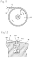
- First, as shown in FIG. 11, the tip portion of the
hoop material 91 is folded and inserted in a checkinggroove 93a of the outer periphery of acore drum 93, whereby thehoop material 91 is stopped by connecting it to thecore drum 93. In this state, thecore drum 93 is rotated so that only thehoop material 91 is wound around the outer periphery of thecore drum 93 once at least. Then, thefiller material 92 is stuck on thehoop material 91 so as to be wound in a spiral state. Thereafter, only thehoop material 91 is further wound twice to thrice. Moreover, thehoop material 91 and thefiller material 92 wound in a spiral state are removed from thecore drum 93, thereby cutting off the folded area on the tip portion of thehoop material 91, which is inserted in the checkinggroove 93a of thecore drum 93. - An initial portion of the
hoop material 91 to be wound is fixed in a predetermined zone of thehoop material 91 by spot welding or the like. A last portion of thehoop material 91 to be wound is fixed in a predetermined zone of the preceding-round of thewound hoop material 91 by the welding spot or the like. - However, the conventional producing method mentioned above requires that the
hoop material 91 and thefiller material 92 wound in a spiral state are removed from thecore drum 93, before positioning a step for cutting off the tip portion of thehoop material 91 inserted in the checkinggroove 93a of thecore drum 93. Consequently, the number of steps is increased, and it is required to manually perform a cutting operation, thereby incurring an expensive production cost. Moreover, the cut-off portion of thehoop material 91 has to be wasted, which results in a problem wherein a yield of thehoop material 91 is worse. - In order to overcome the above problems, a method shown in FIG. 12 is proposed as below. A pressing force is applied to the tip portion of the
hoop material 91, thereby forming aflat portion 91a. A checkinghole 91b is piercingly formed on theflat portion 91a. On the other hand, thecore drum 93 is provided with a checkingpin 94 whose tip can protrude or retract elastically from the outer periphery of thecore drum 93. The checkingpin 94 catches the checkinghole 91b of thehoop material 91, thus winding thehoop material 91 around thecore drum 93. (See a gazette of Japanese Patent Publication No. H8-33180.) - According to the method, the step of cutting off the tip portion of the
hoop material 91 is not required. However, it is required to form theflat portion 91a for providing the checkinghole 91b by a step of applying the pressure or the like to the tip portion. A width of the tip portion after forming theflat portion 91a, is greater than one of the rest portion thereof, whereby local unevenness is generated on the sealing surface of the completed gasket owing to a shape of the tip portion thereof. As a result, there is a fear wherein the unevenness adversely affects the sealing property. - Furthermore, a great gap is generated between the
flat portion 91a andchevron portions round hoop material 91 wound around the outer periphery thereof, whereby welding theflat portion 91a to thehoop material 91 on the outer periphery thereof is not ensured, thereby, in some cases, causing a problem wherein it is easy to separate theflat portion 91a therefrom. - In addition, though the second-
round hoop material 91 directly wound around the outer periphery thereof unforcedly presses the checkingpin 94 to move downwardly, the operation of winding the first-round hoop material 91 is not fully completed at the time when the checkingpin 94 is pressed to move downwardly. Moreover, thehoop material 91 is intensively drawn, thereby increasing the contact pressure between the checkingpin 94 and thechecking hole 91b. In some cases, the unforced friction between the tip portion thereof and thechecking hole 91b greatly damages the tip portion of the checkingpin 94, when the checkingpin 94 is pressed to move downwardly, with the result that there are problems wherein durability of the device is bad and the operation for often refilling the checkingpin 94 is required. - The present invention has been accomplished in view of the above circumstances.
- An object of the present invention is to provide a method of producing a spiral wound gasket for ensuring excellent sealing property and a device for producing the same.
- Another object of the present invention is to provide a method of producing a spiral wound gasket wherein there is no fear in which a tip portion of a hoop material is separated from an outer periphery of the hoop material, and a device for producing the same.
- A further object of the present invention is to provide a method of producing a spiral wound gasket which is excellent in durability, and a device for producing the same.
- In order to achieve the objects, a method of producing a spiral wound gasket of the present invention, wherein a tip portion of a hoop material having a chevron or wave shaped section is stopped by connecting it to a core drum for winding the hoop material, the core drum is rotated so as to wind the hoop material around an outer periphery of the core drum once at least, thereby overlapping a filler material onto the hoop material so that both of them are wound in a spiral state, comprises the steps of:
- forming a checking stepped-portion by cutting and raising a chevron portion of the tip portion of the hoop material or a valley portion thereof,
- rotating the core drum in a state wherein the checking stepped-portion of the hoop material is caught by a checking pawl which makes the tip portion protrude from the outer periphery of the core drum, thereby winding the hoop material around the outer periphery of the core drum once at least,
- overlapping the filler material onto the hoop material together so that the both of them are wound in a spiral state,
- retracting the checking pawl from the outer periphery of the core drum at a predetermined time after winding the hoop material around the outer periphery of the core drum once at least, thereby separating the checking pawl from the checking stepped-portion.
-
- According to the method of producing the spiral wound gasket, the checking stepped-portion for being caught by the checking pawl is formed by cutting and raising the chevron portion or the valley portion of the tip portion of the hoop material. Therefore, it is not required to form a flat portion on the tip portion of the hoop material. This enables a width of the tip portion of the hoop material to correspond to one of the rest portion thereof, thereby preventing local unevenness from being generated on the sealing surface of the gasket. Furthermore, this never generates a great gap between the tip portion of the hoop material and the hoop material wound around the outer periphery thereof, thereby making it possible to surely weld the tip portion of the hoop material to the hoop material of the outer periphery thereof. Still furthermore, at a predetermined time after winding the hoop material around the outer periphery of the core drum once at least, the checking pawl is recessed from the outer periphery of the core drum with the result that the checking pawl can be separated from the checking stepped-portion in a state of decreasing the contact pressure between the checking pawl and the checking stepped-portion. Consequently, there is no fear wherein the friction between it and the hoop material greatly damages the checking pawl.
- Preferably, the step of cutting and raising chevron portions of the tip portion of the hoop material or a valley portion thereof is performed at the same time while a step of separating a preceding hoop material from a following hoop material by cutting is performed.
- This enables the gasket to be efficiently produced, in comparison with a case wherein the step of cutting and raising the chevron portion or the valley portion and the step of cutting the hoop material are separately performed.
- The hoop material is provided with the plural chevron portions, and the checking stepped-portion may be formed on at least one of the plural chevron portions of the hoop material. Alternatively, the checking stepped-portions may be formed on all of plural chevron portions of the hoop material. When the checking stepped-portion is formed in this manner, the tip portion of the hoop material is surely and firmly stopped by connecting it to the checking pawl.
- Preferably, the step of cutting and raising the chevron portion of the tip portion of the hoop material or the valley portion thereof is performed after the hoop material having the flat section is shaped into one having a chevron or wave shaped section, and before the
core drum 2 is supplied with the shaped hoop material. - According to a device for producing a spiral wound gasket of the present invention, wherein a tip portion of a hoop material having a chevron or wave shaped section is stopped by connecting it to a core drum for winding the hoop material, the core drum is rotated so as to wind the hoop material around an outer periphery of the core drum once at least, thereby overlapping a filler material onto the hoop material so that both of them are wound in a spiral state, comprises:
- a checking stepped-portion forming means for forming a checking stepped-portion by cutting and raising a chevron portion of the tip portion of the hoop material or a valley portion thereof,
- a checking pawl housed in the core drum, having a tip portion which can protrude or retract from the outer periphery of the core drum, for catching the checking stepped-portion of the hoop material by the tip portion, in a state wherein the tip portion is protruded from the outer periphery of the core drum, and
- a checking pawl driving means for making the checking pawl protrude or retract from the outer periphery of the core drum.
-
- According to the device for producing the spiral wound gasket, the checking stepped-portion forming means makes the tip portion of the hoop material to be cut and raised, thereby making it possible to form the checking stepped-portion. Moreover, the checking pawl driving means makes the tip portion of the checking pawl protrude from the outer periphery of the core drum, whereby the checking stepped-portion of the hoop material can be caught by the tip portion of the checking pawl. In this state, the core drum is rotated thereby making it possible to wind the hoop material around the outer periphery of the core drum once at least. Thereafter, the filler material is stuck on the hoop material. This can lead to alternatively winding them around it in a spiral state. In addition, at the predetermined time after winding the hoop material around the outer periphery of the core drum once at least, the checking pawl driving means makes the checking pawl retract from the outer periphery of the core drum, thereby enabling the checking pawl to be separated from the checking stepped-portion.
- Thus, the device of producing the spiral wound gasket does not require to form the flat portion on the tip portion of the hoop material, because the gasket has a structure wherein the checking stepped-portion formed by cutting and raising the chevron portion or the valley portion of the tip portion of the hoop material catches the checking pawl. Therefore, the axial width of the tip portion of the hoop material can be kept to correspond to one of the rest portion with the result that local unevenness is not generated on the sealing surface of the gasket, and a great gap is not generated between the tip portion of the hoop material and the second-round hoop material directly wound around the outer periphery thereof. Then, the tip portion of the hoop material can be surely fixed in the predetermined portion of the second-round hoop material on the outer periphery thereof by the spot welding or the like. Furthermore, at the predetermined time after winding the hoop material around the outer periphery of the core drum once at least, the checking pawl is structurally retracted from the outer periphery of the core drum so as to separate the checking pawl from the checking stepped-portion. Consequently, in the state wherein the contact pressure between the hoop material and the checking pawl is decreased, the checking pawl can be separated from the checking stepped-portion. Therefore, there is no fear wherein the checking pawl is damaged by the forced friction between it and the hoop material.
- Preferably, the checking pawl driving means includes:
- a slider housed in the core drum in a state of mounting the checking pawl thereon, being movable in a radial direction of the core drum,
- an eccentric cam engaged with the slider, so as to be eccentric to an axis of the core drum, and
- a rotative shaft concentrically disposed on the axis of the core drum, for rotating the eccentric cam.
-
- In this manner, the rotative shaft makes the eccentric cam rotate thereby moving the slider to a radial direction of the core drum and enabling the checking pawl to be protruded or retracted from the outer periphery of the core drum. Therefore, a simple mechanism enables the checking pawl to be protruded or retracted from the outer periphery of the core drum.
- Preferably, the checking stepped-portion forming means includes:
- a forming punch being vertically movable, and a receiving die disposed so as to be opposed to the forming punch,
- a cutting blade accompanied with the forming punch of the checking stepped-portion forming means, being vertically movable, and
- a receiving blade integrally disposed on the receiving die, and functioning as the pair to the cutting blade.
-
- The above and other features and advantages of the invention will become more apparent from the following description of preferred embodiments.
-
- FIG. 1 is a cutting perspective view of an essential portion of one embodiment of a device for producing a spiral wound gasket according to the present invention.
- FIG. 2 is a schematic front view of the device for producing a spiral wound gasket.
- FIG. 3A is a perspective view of a checking stepped-portion.
- FIG. 3B is a sectional view of the checking stepped-portion.
- FIG. 4 is a perspective view of a checking stepped-portion forming means.
- FIG. 5 is a schematic front view illustrating a step of producing the gasket.
- FIG. 6 is a schematic front view illustrating a step of producing the gasket.
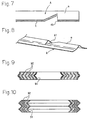
- FIG. 7 is a sectional view illustrating another embodiment of the checking stepped-portion.
- FIG. 8 is a perspective view illustrating further another embodiment of the checking stepped-portion.
- FIG. 9 is a sectional view of a hoop material.
- FIG. 10 is a sectional view of another hoop material.
- FIG. 11 is a schematic front view illustrating a conventional example.
- FIG. 12 is a sectional view illustrating an essential portion of another conventional example.
-
- Referring now to the drawing, preferred embodiments of the invention are described below.
- FIG. 2 is a schematic front view of a producing device for producing a spiral wound gasket. The producing device is used for winding both a hoop material A and a filler material B shown in FIG. 5, which are overlapped with each other, in a spiral state. A main portion of the producing device comprises a checking stepped-
portion forming means 1 for forming checking stepped-portions A1 shown in FIG. 3A or 3B on a tip portion of the hoop material A, acore drum 2 for winding the hoop material A and the filler material B, a checkingpawl 3 housed in thecore drum 2, whose tip portion can be protruded or retracted from an outer periphery of thecore drum 2, and a checking pawl driving means 4 for protruding or retracting the tip portion of the checkingpawl 3 from the outer periphery of the core drum. - The hoop material A has a flat sectional shape when it is drawn from a wound roll. Such a hoop material A is shaped so as to have a wave shaped section including two chevron portions m, m formed by means of a pair rollers R. (See FIG. 3). The hoop material A is subjected to such a shaping process, before the
core drum 2 is supplied to the hoop material A. The quality of the material of the hoop material A is selected from among stainless steel including SUS 304, Inconel, aluminum or the like. Stainless steel is particularly preferable in view of heat-resistance and cost. - As specifically shown in FIG. 4, the checking stepped-
portion forming means 1 includes a forming punch 1a being vertically movable by a driving portion which is not shown in the figures, and a receivingdie 1b disposed so as to be opposite to the forming punch 1a. The forming punch 1a and the receiving die 1b are positioned between thecore drum 2 and the roller R. In the checking stepped-portion forming means 1, the two chevron portions m, m of the tip portion of the hoop material A are respectively cut and raised in an inwardly inclined state, thereby forming the checking stepped-portions A1 shown in FIGs. 3A and 3B. A checking surface of the each checking stepped-portion A1 is cut and raised at right angles to a longitudinal direction of the hoop material A, so as to be easily caught by the tip portion of the checkingpawl 3. The receivingdie 1b is provided with two chevron portions 1c, 1c so as to correspond to the shape of the inner surface of the hoop material A. - Moreover, between the forming punch 1a or the receiving die 1b and the
core drum 2, acutting blade 6a and areceiving blade 6b for separating the preceding hoop material A from the following hoop material A by cutting, are attachably or detachably disposed. (See FIGs. 2 and 4). In this embodiment, thecutting blade 6a is fixed in the driving portion so as to accompany with the forming punch 1a of the checking stepped-portion forming means 1 and move vertically. Furthermore, thereceiving blade 6b is integrated with the receiving die 1b of the checking stepped-portion forming means 1. - As shown in FIG. 1, the
core drum 2 is annular, whose outer diameter and width respectively correspond to an inner diameter and a width of a gasket G to be produced (cf. FIG. 6), and whose inner periphery is integrated with a hollow supportingbody 21. The supportingbody 21 is rotatably supported by an axial box (not shown) via abearing 22, and rotatively driven in a clockwise direction on FIG. 2 by the driving portion (not shown). The inside of thecore drum 2 is provided with aslit 23 for introducing aslider 41 described as below from the outer periphery side to an axial core portion. - The checking
pawl 3 has a substantially parallelepiped base portion 31 whose tip portion is provided with two checking protrusive-portions end surface 32a of thechecking projecting portion 32 is orientated in a substantial radial direction of thecore drum 2. In addition, the checkingpawl 3 is slidably introduced into a recessedgroove 24 formed from the outer periphery of thecore drum 2 to either side surface. - The checking pawl driving means 4 includes the
slider 41 housed in thecore drum 2, aneccentric cam 42 engaged with theslider 41, and arotative shaft 43 for rotating theeccentric cam 42 at a predetermined angle. - The
slider 41 is like a flat plate, which is fitted into theslit 23 formed on thecore drum 2 so as to be slidable in a radial direction of thecore drum 2. Moreover, a base end portion of theslider 41 has anengaging hole 41a being a long hole, and theengaging hole 41a is relatively rotatably fitted into theeccentric cam 42. Furthermore, one of the angled portions of the tip ends of theslider 41 is provided with a recessedportion 41b (see FIG. 2), and the checkingpawl 3 is fixed in the recessedportion 41b. - The
rotative shaft 43 is aligned with the supportingbody 21 in the hollow inside of the supportingbody 21. Therotative shaft 43 is relatively rotatably supported by the supportingbody 21 via abearing 44. Additionally, independently of the supportingbody 21, it is rotatable owing to the driving portion not shown. Theeccentric cam 42 is integrally and rotatably fixed in therotative shaft 43 in a state wherein theeccentric cam 42 is eccentric to the axial core of supportingbody 21 in a predetermined amount. - According to the checking pawl driving means 4, the
rotative shaft 43 is rotated, thereby making it possible to slide theslider 41 in a radial direction of thecore drum 2 via theeccentric cam 42. This makes the checking protrusive-portion 32 of the checkingpawl 3 protrude or retract from the outer periphery of thecore drum 2. Therefore, a simple structure enables the checkingpawl 3 to be protruded or retracted from the outer periphery of thecore drum 2. - Next, a method of producing the spiral wound gasket by employing the producing device of the above structure is described, referring to FIGs. 2 to 6.
- First, the hoop material A drawn from the wound roll is shaped by a pair of the rollers R so as to have a wave shaped section, before the each of two chevron portions m, m of the tip portion of the hoop material A is cut and raised by the forming punch 1a and the receiving die 1b of the checking stepped-
portion forming means 1, thus forming the checking stepped-portions A1. (See FIGs. 2 and 3.) - Then, in a state wherein the each checking stepped-portion A1 is stopped by connecting it to the checking protrusive-
portion 32 of the checkingpawl 3 slightly protruding from the outer periphery of the core drum 2 (cf. FIG. 2), thecore drum 2 is drivingly rotated, thereby winding the hoop material A around the outer periphery of thecore drum 2 once at least. At that moment, the each checking stepped-portion A1 formed on the each chevron portion m of the hoop material A is stopped to connect it to the checking protrusive-portion 32 of the checkingpawl 3. As a result, the tip portion of the hoop material A can be surely and firmly caught and stopped by the checkingpawl 3. Therefore, the hoop material A can be surely wound. - When it is completed to wind the hoop material A once at least, an initial portion of the hoop material A to be wound (i.e., the tip portion) is subjected to a spot welding for welding the initial portion thereof to a predetermined position of the second-round hoop material A wound around the outer periphery for the second time. In this time, the sectional surface of the tip portion of the hoop material A including the checking stepped-portions A1 is kept wave-shaped, whereby the tip portion of the hoop material A can fit onto the second-round thereof without any great gap. Therefore, the both of them can be easily and surely welded to each other.
- Then, a lower surface of the hoop material A is supplied with the filler material B, and as shown in FIG. 5, the both of them are overlapped with each other so that they are wound in a spiral state at the predetermined number of times. Thereafter, supply of the filler material B is stopped, and only the hoop material A is wound at plural times. The filler material B is selected from among ceramic, expanded graphite, asbestos, 4-fluorinated ethylene resin or the like. Particularly, ceramic is preferable in view of strength.
- When single winding of the hoop material A is completed, the preceding hoop material A is cut and separated from the following hoop material A by the
cutting blade 6a and thereceiving blade 6b, at the same time while the each checking stepped-portion A1 is formed on the tip portion of the following hoop material A by the forming punch 1a and the receivingdie 1b. Thus, cutting the hoop material A and forming the checking stepped-portions A1 are simultaneously performed, thereby improving productivity in comparison with a case of performing them separately in a staggering state. - A last portion of the preceding hoop material A to be wound (i.e., a back end portion) is pressed against a wound portion of the hoop material A which directly underlies the last portion of the hoop material A, thereby applying the spot welding to the both of them. Consequently, the spiral wound gasket G shown in FIG. 6 is obtained.
- Moreover, on or after the time when the hoop material A is wound once at least, the
rotative shaft 43 is rotated, thereby protruding or retracting the checking protrusive-portion 32 of the checkingpawl 3 from the outer periphery of thecore drum 2 as shown in FIG. 6, with the result that the checkingpawl 3 can be separated from the checking stepped-portion A1 of the hoop material A. - By the way, the hoop material A is wound around the
core drum 2 once at least while applying an appropriate tensile force (preferably, 40 to 60Kg/cm2) thereto. Therefore, in making thechecking projecting portion 32 protrude or retract from the outer periphery of thecore drum 2, the portion already wound around thecore drum 2 in the hoop material A is more firmly wound around the outer periphery of thecore drum 2 by the friction force. In other words, it prevents the hoop material A from slipping off thecore drum 2. Therefore, in a state wherein a contact pressure between the checkingpawl 3 and the checking stepped-portion A1 is slightly less than that therebetween in a stage of beginning to wind the hoop material A, the checking protrusive-portion 32 is smoothly retracted in an inside of thecore drum 2, the checkingpawl 3 can be cut and separated from the checking stepped-portions A1. In this manner, according to the present configuration, under a state wherein the checkingpawl 3 and the checking stepped-portions A1 are firmly touched with each other, they are separated, thereby preventing forced friction or the like from being caused. This can prevent the checkingpawl 3 from being early damaged, and enhance durability of the device. - Finally, after the gasket G is removed from the
core drum 2, the above operations are repeated, thus making it possible to produce subsequently the gasket G. - According to the above producing method, the tip portion of the hoop material A can be caught by the checking
pawl 3 without forming a flat portion on the tip portion of the hoop material A owing to applying pressure, whereby the width of the tip portion of the hoop material A can be adjusted so as to correspond to one of the rest portion. As a result, this can prevent local unevenness from being generated on the sealing surface of the gasket G, and ensure an excellent sealing property. - The above embodiment illustrates a case wherein the checking stepped-portions A1 are respectively formed on the two chevron portions m, m of the hoop material A. Alternatively, even in case of forming the checking stepped-portion A1 on only one of the chevron portions m, m, the tip portion of the hoop material A can be, surely and firmly to a certain degree, caught by the checking
pawl 3. Therefore, the checking stepped-portion A1 may be formed on at least one of the plural chevron portions m, m. - In addition, as shown in FIG. 7, the checking stepped-portion A1 may be formed by cutting and raising a valley portion t of the tip portion of the hoop material A upwardly. Furthermore, the checking pawl driving means 4 has a structure wherein, instead of the
eccentric cam 42, a wedge drivingly slidable in an axial direction of the supportingbody 21 may be used so that theslider 41 can be slid in a radial direction of thecore drum 2 by the wedge. Alternatively, different kinds of modified designs including a structure wherein the checking stepped-portion forming means 1 comprises a pair of rollers can be applied. - Additionally, the present invention can be applied to the hoop material A having a chevron shaped section as shown in FIG. 8.
- The entire disclosure of Japanese Patent Application No. 10-89418 filed on March 17, 1998 including specification, claims, drawings, and summary are incorporated herein by reference in its entirety.
Claims (8)
- A method of producing a spiral wound gasket wherein a tip portion of a hoop material having a chevron or wave shaped section is stopped by connecting it to a core drum for winding the hoop material, the core drum is rotated so as to wind the hoop material around an outer periphery of the core drum once at least, thereby overlapping a filler material onto the hoop material so that both of them are wound in a spiral state, comprising the steps of:forming a checking stepped-portion by cutting and raising a chevron portion of the tip portion of the hoop material or a valley portion thereof,rotating the core drum in a state wherein the checking stepped-portion of the hoop material is caught by a checking pawl which makes the tip portion protrude from the outer periphery of the core drum, thereby winding the hoop material around the outer periphery of the core drum once at least,overlapping the filler material onto the hoop material together so that the both of them are wound in a spiral state,retracting the checking pawl from the outer periphery of the core drum at a predetermined time after winding the hoop material around the outer periphery of the core drum once at least, thereby separating the checking pawl from the checking stepped-portion.
- A method of producing a spiral wound gasket according to claim 1, wherein the step of cutting and raising a chevron portion of the tip portion of the hoop material or a valley portion thereof, is performed at the same time while a step of separating a preceding hoop material from a following hoop material by cutting is performed.
- A method of producing a spiral wound gasket according to claim 1, wherein the hoop material is provided with the plural chevron portions, and the checking stepped-portion is formed on at least one of the plural chevron portions of the hoop material.
- A method of producing a spiral wound gasket according to claim 1, wherein the hoop material is provided with the plural chevron portions, and the checking stepped-portions are formed on all of the plural chevron portions of the hoop material.
- A method of producing a spiral wound gasket according to claim 1, wherein the step of cutting and raising the chevron portion of the tip portion of the hoop material or the valley portion thereof is performed after the hoop material having the flat section is shaped into one having a chevron or wave shaped section, and before the core drum 2 is supplied with the shaped hoop material.
- A device for producing a spiral wound gasket wherein a tip portion of a hoop material having a chevron or wave shaped section is stopped by connecting it to a core drum for winding the hoop material, the core drum is rotated so as to wind the hoop material around an outer periphery of the core drum once at least, thereby overlapping a filler material onto the hoop material so that both of them are wound in a spiral state, comprising:a checking stepped-portion forming means for forming a checking stepped-portion by cutting and raising a chevron portion of the tip portion of the hoop material or a valley portion thereof,a checking pawl housed in the core drum, having a tip portion which can protrude or retract from the outer periphery of the core drum, for catching the checking stepped-portion of the hoop material by the tip portion, in a state wherein the tip portion is protruded from the outer periphery of the core drum, anda checking pawl driving means for making the checking pawl protrude or retract from the outer periphery of the core drum.
- A device for producing a spiral wound gasket according to 6, wherein the checking pawl driving means includesa slider housed in the core drum in a state of mounting the checking pawl thereon, being movable in a radial direction of the core drum,an eccentric cam engaged with the slider, so as to be eccentric to an axis of the core drum, anda rotative shaft concentrically disposed on the axis of the core drum, for rotating the eccentric cam.
- A device for producing a spiral wound gasket according to 6, wherein the checking stepped-portion forming means includesa forming punch being vertically movable, and a receiving die disposed so as to be opposed to the forming punch,a cutting blade accompanied with the forming punch of the checking stepped-portion forming means, being vertically movable, anda receiving blade integrally disposed on the receiving die, and functioning as the pair to the cutting blade.
Applications Claiming Priority (2)
| Application Number | Priority Date | Filing Date | Title |
|---|---|---|---|
| JP8941898 | 1998-03-17 | ||
| JP10089418A JP2882602B1 (en) | 1998-03-17 | 1998-03-17 | Method and apparatus for manufacturing spiral gasket |
Publications (3)
| Publication Number | Publication Date |
|---|---|
| EP0943848A2 true EP0943848A2 (en) | 1999-09-22 |
| EP0943848A3 EP0943848A3 (en) | 2000-07-05 |
| EP0943848B1 EP0943848B1 (en) | 2004-06-02 |
Family
ID=13970116
Family Applications (1)
| Application Number | Title | Priority Date | Filing Date |
|---|---|---|---|
| EP99104312A Expired - Lifetime EP0943848B1 (en) | 1998-03-17 | 1999-03-03 | A method of producing a spiral wound gasket and a device for producing the same |
Country Status (6)
| Country | Link |
|---|---|
| US (1) | US6195867B1 (en) |
| EP (1) | EP0943848B1 (en) |
| JP (1) | JP2882602B1 (en) |
| KR (1) | KR100316699B1 (en) |
| CN (1) | CN1106517C (en) |
| DE (1) | DE69917703T2 (en) |
Families Citing this family (8)
| Publication number | Priority date | Publication date | Assignee | Title |
|---|---|---|---|---|
| US6665925B1 (en) | 2001-12-11 | 2003-12-23 | Acadia Elastomers Corporation | Apparatus and method for manufacturing rubber-wrapped spiral wound gaskets |
| US6926285B1 (en) | 2001-12-11 | 2005-08-09 | Acadia Elastomers Corporation | Jacketed spiral wound gasket |
| US6823579B2 (en) * | 2002-02-27 | 2004-11-30 | Manegro Administracao E Participacoes Ltda. | Portable platform for use in gasket manufacture |
| US20070176373A1 (en) * | 2006-01-28 | 2007-08-02 | Steven Suggs | Low stress / anti-buckling spiral wound gasket |
| JP4895008B2 (en) * | 2006-05-12 | 2012-03-14 | Nok株式会社 | Gasket mold and manufacturing method |
| DE102014111015A1 (en) * | 2014-08-04 | 2016-02-04 | Adolf Schnorr Gmbh & Co. Kg | Method for producing a strip spring and bending device for the production thereof |
| IT201600095770A1 (en) * | 2016-09-23 | 2018-03-23 | Gsket S R L | MACHINE FOR THE PRODUCTION OF SPIRALIZED GASKETS |
| KR102297285B1 (en) * | 2021-04-27 | 2021-09-01 | 위성철 | Sealing element winding device for spiral wound gasket |
Citations (2)
| Publication number | Priority date | Publication date | Assignee | Title |
|---|---|---|---|---|
| JPH0833180A (en) | 1994-07-14 | 1996-02-02 | Showa Electric Wire & Cable Co Ltd | Air termination box |
| JPH1089418A (en) | 1996-06-20 | 1998-04-07 | Unitta Co Ltd | Toothed belt |
Family Cites Families (13)
| Publication number | Priority date | Publication date | Assignee | Title |
|---|---|---|---|---|
| US2741023A (en) | 1952-09-27 | 1956-04-10 | Standard Pressed Steel Co | Method of making slit pins having continuously bevelled ends |
| US3061224A (en) | 1960-01-18 | 1962-10-30 | Herr Equipment Corp | Apparatus for coiling strip material |
| GB907318A (en) | 1960-05-19 | 1962-10-03 | Ventrex Roofing Ltd | An improved method and apparatus for the manufacture of louvred corrugated sheeting |
| US3331564A (en) | 1966-02-02 | 1967-07-18 | Mastereel Ind Inc | Hub for film cores and tight-wound marginally apertured film strips |
| US3752416A (en) | 1970-04-03 | 1973-08-14 | Victor Company Of Japan | Automatic winding reel |
| GB1514581A (en) | 1975-05-06 | 1978-06-14 | Lear R | Scroll-forming device |
| JPS5716436A (en) | 1980-07-02 | 1982-01-27 | Canon Inc | Winding spool for camera |
| WO1982000699A1 (en) | 1980-08-22 | 1982-03-04 | Soumar K | Electric fusion pipe fittings |
| DE3134829A1 (en) * | 1981-09-03 | 1983-03-17 | Kempchen & Co Gmbh, 4200 Oberhausen | Apparatus and method for winding a spiral-wound gasket |
| JPH02266164A (en) | 1989-04-07 | 1990-10-30 | Agency Of Ind Science & Technol | Spiral wound gasket and manufacture thereof |
| GB2258018B (en) * | 1991-07-23 | 1994-10-19 | T & N Technology Ltd | Gaskets |
| EP0707906B1 (en) * | 1994-10-22 | 2001-01-24 | AISA S.p.A. | Automatic machine for the production of gaskets |
| US5683091A (en) * | 1995-07-10 | 1997-11-04 | Nichias Corporation | Spiral wound gasket with at least five inner and outer plies secured by at least four welds |
-
1998
- 1998-03-17 JP JP10089418A patent/JP2882602B1/en not_active Expired - Fee Related
-
1999
- 1999-02-22 KR KR1019990005758A patent/KR100316699B1/en not_active IP Right Cessation
- 1999-02-26 US US09/258,274 patent/US6195867B1/en not_active Expired - Lifetime
- 1999-03-03 DE DE69917703T patent/DE69917703T2/en not_active Expired - Fee Related
- 1999-03-03 EP EP99104312A patent/EP0943848B1/en not_active Expired - Lifetime
- 1999-03-11 CN CN99103659A patent/CN1106517C/en not_active Expired - Lifetime
Patent Citations (2)
| Publication number | Priority date | Publication date | Assignee | Title |
|---|---|---|---|---|
| JPH0833180A (en) | 1994-07-14 | 1996-02-02 | Showa Electric Wire & Cable Co Ltd | Air termination box |
| JPH1089418A (en) | 1996-06-20 | 1998-04-07 | Unitta Co Ltd | Toothed belt |
Also Published As
| Publication number | Publication date |
|---|---|
| EP0943848A3 (en) | 2000-07-05 |
| EP0943848B1 (en) | 2004-06-02 |
| JPH11264474A (en) | 1999-09-28 |
| CN1106517C (en) | 2003-04-23 |
| CN1229177A (en) | 1999-09-22 |
| KR19990077447A (en) | 1999-10-25 |
| JP2882602B1 (en) | 1999-04-12 |
| DE69917703T2 (en) | 2005-06-09 |
| DE69917703D1 (en) | 2004-07-08 |
| US6195867B1 (en) | 2001-03-06 |
| KR100316699B1 (en) | 2001-12-12 |
Similar Documents
| Publication | Publication Date | Title |
|---|---|---|
| US8046916B2 (en) | Method of, and apparatus for, manufacturing metallic bellows | |
| EP0943848B1 (en) | A method of producing a spiral wound gasket and a device for producing the same | |
| US3905090A (en) | Method of making spiral wound gaskets | |
| US9541224B2 (en) | Method of manufacturing coiled tubing using multi-pass friction stir welding | |
| US5980744A (en) | Beaded center tube | |
| US20110121569A1 (en) | Standing seam connectors for ducting | |
| JP2016518990A (en) | Method for producing multi-layered large diameter pipes | |
| JP2009082930A (en) | Method and apparatus for forming tubular material | |
| KR100286523B1 (en) | Method and apparatus for producing helically wound lock-seam tubing | |
| JP2001212639A (en) | Manufacturing method for band for cvt belt and the band manufactured by the method | |
| US7117709B2 (en) | Flange sleeve and method for the production thereof | |
| US6513219B1 (en) | Method for producing a ring collar, notably for a clutch mechanism in particular for a motor vehicle | |
| EP0631368B1 (en) | Coil winding method and a combination of a coil winding jig and a coil winding machine for carrying out the same | |
| US7775076B2 (en) | Pinch-point lock-seam tubing, pinch point seaming devices, and methods for manufacturing stabilized lock-seam tubing | |
| US3132544A (en) | Positioning and splicing apparatus for positioning and splicing webs | |
| KR20020043554A (en) | Improved gasketed aerosol mounting cup | |
| KR102378841B1 (en) | Slew-actuated piercing of radial walls | |
| NL2005086A (en) | Device for forming a flared hoop, mandrel, method for forming a flared hoop, flared hoop. | |
| US6425171B1 (en) | Shrouded tube termination method | |
| JP3336166B2 (en) | Method of manufacturing spiral wound gasket | |
| EP0627055B1 (en) | Welded wear sleeve for lubricant seals | |
| JP3092861B2 (en) | Band tightening device | |
| JP2001246675A (en) | Method and device for forming bent part of material for carcass ply | |
| US4239834A (en) | Metal substrate formation with torx recess mandrel | |
| JP2005139005A (en) | Joining paper tube, and method and device for manufacturing the paper tube |
Legal Events
| Date | Code | Title | Description |
|---|---|---|---|
| PUAI | Public reference made under article 153(3) epc to a published international application that has entered the european phase |
Free format text: ORIGINAL CODE: 0009012 |
|
| 17P | Request for examination filed |
Effective date: 19990317 |
|
| AK | Designated contracting states |
Kind code of ref document: A2 Designated state(s): DE FR GB |
|
| AX | Request for extension of the european patent |
Free format text: AL;LT;LV;MK;RO;SI |
|
| PUAL | Search report despatched |
Free format text: ORIGINAL CODE: 0009013 |
|
| AK | Designated contracting states |
Kind code of ref document: A3 Designated state(s): AT BE CH CY DE DK ES FI FR GB GR IE IT LI LU MC NL PT SE |
|
| AX | Request for extension of the european patent |
Free format text: AL;LT;LV;MK;RO;SI |
|
| AKX | Designation fees paid |
Free format text: DE FR GB |
|
| GRAP | Despatch of communication of intention to grant a patent |
Free format text: ORIGINAL CODE: EPIDOSNIGR1 |
|
| GRAS | Grant fee paid |
Free format text: ORIGINAL CODE: EPIDOSNIGR3 |
|
| GRAA | (expected) grant |
Free format text: ORIGINAL CODE: 0009210 |
|
| AK | Designated contracting states |
Kind code of ref document: B1 Designated state(s): DE FR GB |
|
| REG | Reference to a national code |
Ref country code: GB Ref legal event code: FG4D |
|
| REF | Corresponds to: |
Ref document number: 69917703 Country of ref document: DE Date of ref document: 20040708 Kind code of ref document: P |
|
| ET | Fr: translation filed | ||
| PLBE | No opposition filed within time limit |
Free format text: ORIGINAL CODE: 0009261 |
|
| STAA | Information on the status of an ep patent application or granted ep patent |
Free format text: STATUS: NO OPPOSITION FILED WITHIN TIME LIMIT |
|
| 26N | No opposition filed |
Effective date: 20050303 |
|
| PGFP | Annual fee paid to national office [announced via postgrant information from national office to epo] |
Ref country code: GB Payment date: 20090325 Year of fee payment: 11 |
|
| PGFP | Annual fee paid to national office [announced via postgrant information from national office to epo] |
Ref country code: DE Payment date: 20090320 Year of fee payment: 11 |
|
| PGFP | Annual fee paid to national office [announced via postgrant information from national office to epo] |
Ref country code: FR Payment date: 20090312 Year of fee payment: 11 |
|
| GBPC | Gb: european patent ceased through non-payment of renewal fee |
Effective date: 20100303 |
|
| REG | Reference to a national code |
Ref country code: FR Ref legal event code: ST Effective date: 20101130 |
|
| PG25 | Lapsed in a contracting state [announced via postgrant information from national office to epo] |
Ref country code: FR Free format text: LAPSE BECAUSE OF NON-PAYMENT OF DUE FEES Effective date: 20100331 |
|
| PG25 | Lapsed in a contracting state [announced via postgrant information from national office to epo] |
Ref country code: DE Free format text: LAPSE BECAUSE OF NON-PAYMENT OF DUE FEES Effective date: 20101001 |
|
| PG25 | Lapsed in a contracting state [announced via postgrant information from national office to epo] |
Ref country code: GB Free format text: LAPSE BECAUSE OF NON-PAYMENT OF DUE FEES Effective date: 20100303 |