EP0943540B1 - Closure preventive device for water jet propulsion type outboard motor - Google Patents
Closure preventive device for water jet propulsion type outboard motor Download PDFInfo
- Publication number
- EP0943540B1 EP0943540B1 EP98947800A EP98947800A EP0943540B1 EP 0943540 B1 EP0943540 B1 EP 0943540B1 EP 98947800 A EP98947800 A EP 98947800A EP 98947800 A EP98947800 A EP 98947800A EP 0943540 B1 EP0943540 B1 EP 0943540B1
- Authority
- EP
- European Patent Office
- Prior art keywords
- screen
- engagement portion
- preventing apparatus
- blockage preventing
- open
- Prior art date
- Legal status (The legal status is an assumption and is not a legal conclusion. Google has not performed a legal analysis and makes no representation as to the accuracy of the status listed.)
- Expired - Lifetime
Links
Images



Classifications
-
- B—PERFORMING OPERATIONS; TRANSPORTING
- B63—SHIPS OR OTHER WATERBORNE VESSELS; RELATED EQUIPMENT
- B63H—MARINE PROPULSION OR STEERING
- B63H5/00—Arrangements on vessels of propulsion elements directly acting on water
- B63H5/07—Arrangements on vessels of propulsion elements directly acting on water of propellers
- B63H5/16—Arrangements on vessels of propulsion elements directly acting on water of propellers characterised by being mounted in recesses; with stationary water-guiding elements; Means to prevent fouling of the propeller, e.g. guards, cages or screens
- B63H5/165—Propeller guards, line cutters or other means for protecting propellers or rudders
-
- B—PERFORMING OPERATIONS; TRANSPORTING
- B63—SHIPS OR OTHER WATERBORNE VESSELS; RELATED EQUIPMENT
- B63H—MARINE PROPULSION OR STEERING
- B63H11/00—Marine propulsion by water jets
- B63H11/01—Marine propulsion by water jets having means to prevent foreign material from clogging fluid passage way
-
- F—MECHANICAL ENGINEERING; LIGHTING; HEATING; WEAPONS; BLASTING
- F02—COMBUSTION ENGINES; HOT-GAS OR COMBUSTION-PRODUCT ENGINE PLANTS
- F02B—INTERNAL-COMBUSTION PISTON ENGINES; COMBUSTION ENGINES IN GENERAL
- F02B61/00—Adaptations of engines for driving vehicles or for driving propellers; Combinations of engines with gearing
- F02B61/04—Adaptations of engines for driving vehicles or for driving propellers; Combinations of engines with gearing for driving propellers
- F02B61/045—Adaptations of engines for driving vehicles or for driving propellers; Combinations of engines with gearing for driving propellers for marine engines
Definitions
- the present invention relates to a blockage preventing apparatus for a water jet propulsion unit used in a hull.
- a water jet propulsion unit for a hull sucks and injects water in the neighborhood of the water surface, it is blocked in a short time when sucking floating matters or pieces. Due to this, a screen is provided at an intake to prevent large floating pieces from being sucked into a suction casing.
- JP-U-1141200 discloses a blockage preventing apparatus according to the preamble portion of claim 1.
- the present invention has been made in consideration of the conventional problems stated above. It is therefore an object of the present invention to provide a blockage preventing apparatus capable of ensuring the elimination of floating matters strongly clinging to a screen.
- a first aspect of the present invention is a blockage preventing apparatus used for a water jet propulsion unit provided with a casing member including a lower opening at a front end, a transom opening at a rear end and an internal space between the lower opening and the transom opening, and vanes arranged within the internal space and rotated for sucking water from the lower opening to inject the water from the transom opening, the blockage preventing apparatus comprising:
- the blockage preventing apparatus may further comprise an open/close driving machine for moving the second engagement portion, and the second engagement portion may be set such that a movement region of the second engagement portion from the first position to the second position overlaps a movement region of the first engagement portion and the movement region of the second engagement portion beyond the second position is out of the movement region of the first engagement portion.
- the open/close driving machine may includes a piston moved forward and backward by oil pressure, and the second engagement portion may be provided at the piston.
- the second engagement portion is appropriately moved from the first position toward the second position.
- the second engagement portion is engaged with and presses the first engagement portion and the screen is moved from the closed position to the open position against the urging force of the urging member, thereby opening the lower opening.
- the screen opens from backward.
- the second engagement portion moves beyond the second position, the second engagement portion is disengaged from the first engagement portion so that the screen is momentarily moved to the closed position by the urging force of the urging member.
- the screen opens the lower opening again. In this way, the screen is seen to slowly open the lower opening and then to quickly move to the closed position.
- a second aspect of the present invention is the blockage preventing apparatus according to the first aspect, further comprising open/close controlling means for intermittently actuating the open/close driving machine at predetermined time intervals.
- the intervals at which the open/close control means actuate the open/close driving machine may be set according to the quantity of floating matter.
- the appropriate setting range is not less than 10 seconds and not more than 120 seconds.
- the screen since the screen is opened and closed at predetermined time intervals, the screen is cleaned before the quantity of the floating matters clinging to the screen becomes excessive. This facilitates peeling off the floating matter from the screen and enhances the effect of cleaning the screen.
- a third aspect of the present invention is a blockage preventing apparatus according to the first aspect, further comprising:
- the fourth aspect of the present invention is a blockage preventing apparatus according to the first aspect, further comprising:
- the fifth aspect of the present invention is a blockage preventing apparatus used for a water jet propulsion unit provided with a casing member including a lower opening at a front end, a transom opening at a rear end and an internal space between the lower opening and the transom opening and with vanes arranged within the internal space and rotated for sucking water from the lower opening and for injecting the water from the lateral opening, the blockage preventing apparatus comprising:
- the number of fixed blades may be one. In case of a large water jet propulsion unit, a plurality of fixed blades may be provided according to the number of vanes.
- the fixed blade When the fixed blade is formed integrally with the vane, it is appropriate to select steel or stainless steel as material for the vane.
- the movable blade formed separately may be attached to the vane in view of the need to replace blades due to abrasion and the like.
- the floating matter mixed in the water sucked into the casing member is sheared between the movable blades and the fixed blades, ensuring that the floating matter is driven out together with pressurized water.
- the floating matter is not deposited in the casing member to thereby securely preventing the water jet propulsion unit from being blocked.
- the sixth aspect of the present invention is a blockage preventing apparatus according to the first or fifth aspect, wherein
- forward means forward in navigation direction
- backward means backward in navigation direction
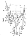
- a water jet propulsion unit 2 is mounted at the stern of a hull 1.
- the water jet propulsion unit 2 is provided with a casing member 50 and an impeller 25.
- the casing member 50 consists of a suction casing 5, a pump casing 10 and an injection casing 12.
- a suction port 7 (opened downward) is provided on one end of the suction casing 5 and the pump casing 10 is provided integrally with the suction casing 5 on the other end thereof.
- the first internal space 51 extending diagonally above backward from the suction port 7 into pump casing 10.
- One end of the injection casing 12 is coupled to the pump casing 10 and an injection port 30 is provided on the other end of the injection casing 12.
- the second internal space 52 is provided within the casings 4 and 6 to transversely extend from the first internal space 51 toward the injection port 30.
- the impeller 25 is provided within the pump casing 10.
- the water below the suction casing 3 is sucked from the suction port 7, passed through the first internal space 51, pressurized by the impeller 25 in the pump casing 10 and injected from the injection port 30 of the injection casing 12.
- the injection of the pressurized water propels the vessel 1.
- a guide vane 11 is provided in the back of the impeller 25 within the second internal space 52 so that a turning flow pressurized by the impeller 25 is rectified into a linear flow.
- An injection nozzle 3 is provided outside the injection port 30 and a reverser 31 for backward motion is provided outside the injection nozzle 3.
- an engine 4 is mounted in front of the propulsion unit 2 of the hull 1.
- a drive shaft 13 is coupled to the engine 4.
- the drive shaft 13 is inserted into the suction casing 5 from the inclined shoulder portion of the suction casing 5 and extended toward the pump casing 10.
- the impeller 25 is concentrically fixed to the rear end of the drive shaft 13. Thus, the driving force of the engine 4 is inputted into the impeller 25 through the drive shaft 13.
- the suction port 7 of the suction casing 5 is provided with a screen 6 for preventing inflow of floating matter.
- the screen 6 is of comb or mesh shape.
- the front end of the screen 6 is coupled to a rotary shaft 16 rotatably supported by the suction casing 5 at the leading edge of the suction port 7.
- the screen 6 is rotatable about the rotary shaft 16 and moves between a closed position at which the suction port 7 is covered with the screen 6 and an open position shifted downward from the suction port 7.
- the base of an L-shaped working shaft 17 is fixed to the rotary shaft 16.
- the working shaft 17 rocks about the rotary shaft 16 following the opening/closing of the screen 6.
- the working shaft 17 is provided with an engagement protrusion (first engagement portion) 21.
- the engagement protrusion 21 protrudes in a direction crossing the rocking direction of the working shaft 17.
- a frame 34 fixed to the hull 1 is arranged above the engine 4.
- a hydraulic cylinder (open/close driving machine) 18 is disposed on the frame 34.
- the hydraulic cylinder 18 has a piston 19 linearly movable forward and backward above the engagement protrusion 21 of the working shaft 17.
- a hook 20 crossing the piston 19 is rotatably provided at the piston 19.
- the hook 20 has an engagement end portion (second engagement portion) 20a protruding downward from the piston 19 and an upper end portion 20b protruding upward from the piston 19.
- the tip end of the piston 19 is coupled to the upper end portion 206 of the hook 20 by a spring 23.
- the spring 23 urges the engagement end portion 20a forward.
- the piston 19 has a protrusion 19a which abuts on the hook 20 and prevents the forward movement of the engagement end portion 20a.
- the spring 23 and the protrusion 19a function to maintain the hook 20 to be positioned in an initial state in which the engagement end portion 20a extends almost at right angle from the piston 19.
- the working shaft 17 and the frame 34 are coupled to each other by two springs (urging members) 22.
- the springs 22 urge the working shaft 17 backward.
- the rear end of the screen 6 in a closed position abuts on the leading edge of the suction port 7.
- the elastic force (urging force) of the springs 22 maintains the working shaft 17 and the screen 6 in the initial position and in the closed position, respectively.
- the springs 22 extends and the working shaft 17 inclines and moves backward from the initial position.
- the engagement protrusion 21 moves backward and the screen 6 moves and opens.
- the pressing force applied to the engagement protrusion 21 is canceled, the working shaft 17 and the screen 6 return to the initial position and the closed position, respectively by the elastic force of the springs 22.
- the engagement end portion 20a is positioned forward with respect to the engagement protrusion 21 of the working shaft 17 in the initial position.
- the movement region of the engagement end portion 20a from the first position to the backward is a linear band shape along the movement line of the piston 19.
- the movement region of the engagement protrusion 21 when the working shaft 17 moves backward from the initial position is a curved band shape along a radii about the rotary shaft 16.
- the movement region of the engagement end portion 20a and that of the engagement protrusion 21 are set such that the movement region of the engagement end portion 20a from the first position to the second position in the back of the first position overlaps that of the engagement protrusion 21 and that the backward movement region of the engagement end portion 20a with respect to the second position is shifted from the movement region of the engagement protrusion 21. Therefore, when the piston moves backward and the engagement end portion 20a moves through the first position to the second position, the engagement end portion 20a is engaged with and presses the rear face of the engagement protrusion 21 and the screen 6 moves from the closed position to the open position against the elastic force of the springs 22.
- the hull 1 is provided with a timer 24 and a control circuit 35 which constitute control means.
- the timer 24 sets time freely in accordance with the state of the water surface on which the hull 1 sails. For instance, in case of the water surface with lot of floating matter, the time is set at 10 seconds, and in case of that with less floating matter, the time is set at 120 seconds.
- the timer 24 outputs a signal to the control circuit 35 at set time intervals.
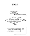
- step S1 when the control circuit 35 is turned on, it is determined whether the control circuit 35 inputs a signal from the timer 24 after the timer 24 is turned on (in a step S1).
- a drive signal is outputted to the hydraulic cylinder 18 and the cylinder 18 is actuated (in a step S2).
- the screen 6 opens and closes once.
- the series of steps stated above are repeated. The screen 6 is, thereby, opened and closed at set time intervals.
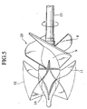
- the impeller 25 includes a hub 9 fixed to the outer periphery of the drive shaft 13 and four vanes 8 protruding from the hub 9.
- Each of the vane 8 is helical and made of steel or stainless steel.
- the proximal portions of the vanes 8 are attached to the hub 9 with their phases shifted one another.
- the outer peripheral edge of the vane 8 is arranged to be adjacent to inner peripheral surface of the pump casing 10 so as to improve the volumetric efficiency and balancing efficiency of the impeller 25.
- the outer peripheral tip end portion of the vane 8 in the forward direction (intake water inflow side) extends in the (forward) direction of the suction casing 5.
- a guide vane 11 protrudes from the central base 14.
- the inlet side edge of the guide vane 11 is adjacent to the outlet side edge of the vane 8.
- the outer peripheral edge of the guide vane 11 is fixed to the inner surface of the injection casing 12.
- a bearing 15 is fitted into the center of the central base 14.
- the tip end of the drive shaft 13 is rotatably supported by the bearing 15.
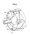
- a sharp blade 8a is integrally formed with each vane 8 at the tip end portion of the suction water inflow-side vane 8.
- a movable blade 8b is formed integrally with the outer edge of the blade 8a.
- Fixed blades 10a protruding into the flow passage of the suction water at three positions on the inner peripheral surface of the suction water inflow-side pump casing 10.
- the fixed blades 10a are arranged in the vicinity of the outside of the rotating locus of the movable blade 8b.
- the fixed blade 10a and the movable blade 8b passing above the blade 10a function as a pair of cutting mechanisms.
- dusts mixed in the suction water from the suction port 7 those at the central portion are cut and crushed by the rotating blades 8a and those at the outer peripheral edge are cut and crushed by the movable blades 8b and the fixed blades 10a.
- the number of vanes 8 and that of the fixed blades 10a are not limited to the above example. Also, in the above embodiment, the blade 8a is formed integrally with the vane 8. In view of abrasion and the like, the blade portion 8a of steel or stainless steel formed independently of the vane 8 may be detachably attached to the vane 8.
- the open/close control circuit 35 is turned on. By doing so, the screen 6 opens and closes the suction port 7 at set time intervals. At this time, the screen 6 is seen to open the suction port 7 slowly and then move quickly to the closed position. Therefore, while the screen 6 slowly moves to the open position, the floating matter such as dusts clinging to the screen 6 is securely driven out by water flow to thereby clean the screen 6. Since the screen 6 quickly returns from the open position to the closed position, it is difficult for floating matter to flow into the suction port 7 while the screen 6 is moving to the open position.
- the screen 6 is opened and closed at preset time intervals, the screen 6 is cleaned before the quantity of floating matter clinging to the screen 6 becomes excessive. This facilitates peeling off the floating matter from the screen 6 and the efficiency of cleaning the screen 6 enhances.
- the floating matter mixed in the water sucked into the casing member 50 is not only cut by the blade portions 8a but also sheared between the movable blades 8b and the fixed blades 10a, ensuring that the floating matter is driven out together with pressurized water. Thus, floating matter is not deposited in the casing member 50 to thereby securely preventing the water jet propulsion unit 2 from being blocked.
- the timer 24 and the control circuit 35 used in the first embodiment are replaced by a rotating speed sensor (rotating speed detecting means) 41, a hull speed sensor (hull speed detecting means) 42 and a control circuit (control means) 43.
- the remaining constituent elements are the same as those in the first embodiment, which description will not be, therefore, given herein.
- the rotating speed sensor 41 detects the rotating speed of the drive shaft (shown in FIG. 2) 13 (rotating speed of the vane 8) and sequentially outputs a detection signal to the control circuit 43.
- the hull speed sensor 42 which is arranged at the bottom of the hull 1 (shown in FIG. 1), detects a hull speed and sequentially outputs a detection signal to the control circuit 43.
- the control circuit 43 estimates the design speed of the hull 1 corresponding to the detected rotating speed of the vane 8.
- the design speed of the hull 1 indicates hull speed at a time no floating matter clings to the screen 6 (shown in FIG. 1).
- the design speed is estimated as follows. the relationship between the rotating speed of the vane 8 and the hull speed in a state in which no floating matter clings to the screen 6 is obtained through experiment in advance and stored in an internal memory. The design speed is then obtained from the relationship and a detected rotating speed. Next, a reduction rate of the hull speed with respect to the design speed is calculated. Finally, when the calculated reduction rate is not more than a predetermined value, an actuating signal is outputted to the hydraulic cylinder 18 (shown in FIG. 1).
- a third embodiment the timer 24 and the control circuit 35 used in the first embodiment are replaced by a pressure sensor (pressure detecting means) 44 and a control circuit (control means) 45. It is noted that the remaining constituent elements are the same as those in the first embodiment, which description will not be, therefore, given herein.
- the pressure sensor 44 which is provided in the suction casing 5 (shown in FIG. 2), detects an internal pressure of the suction casing 5 upstream of the vanes 8 and sequentially outputs a detection signal to the control circuit 45.
- the control circuit 45 determines whether or not the detected internal pressure is less than a preset reference value (e.g., one atmosphere pressure). When it is less than the reference value, the control circuit 45 outputs an actuating signal to the hydraulic cylinder 18 (shown in FIG.1).
- a preset reference value e.g., one atmosphere pressure
- the hydraulic cylinder 18 is actuated in accordance with the reduction of the pressure. It is, therefore, possible to clean the screen 6 before the quantity of floating matter clinging to the screen 6 becomes excessive. This facilitates peeling off the floating matter from the screen 6 and enhances cleaning effect for the screen 6.
- the present invention while the screen slowly moves to the open position, the floating matter clinging to the screen is securely driven out by water flow and the screen is cleaned. Additionally, since the screen quickly returns from the open position to the closed position, it is made difficult for floating matter to flow into the lower opening while the screen is moving to the closed position. Besides, appropriate vibration and impact are applied to the screen by the quick return of the screen from the open position to the closed position. Due to this, the effect of brushing off the floating matter clinging to the screen enhances, thereby securely eliminating the floating matter strongly clinging to the screen. Hence, the present invention is useful as a blockage preventing apparatus for a water jet propulsion unit.
Landscapes
- Chemical & Material Sciences (AREA)
- Engineering & Computer Science (AREA)
- Combustion & Propulsion (AREA)
- Mechanical Engineering (AREA)
- Ocean & Marine Engineering (AREA)
- Structures Of Non-Positive Displacement Pumps (AREA)
- Paper (AREA)
- Cleaning Or Clearing Of The Surface Of Open Water (AREA)
- Hydraulic Turbines (AREA)
Description
Claims (10)
- A blockage preventing apparatus used for a water jet propulsion unit (2) provided with a casing member (50) including a lower opening (7) at a front end, a transom opening (30) at a rear end and an internal space (51) between said lower opening (7) and said transom opening (30), and vanes (8) arranged within said internal space (51) and rotated for sucking water from said lower opening to inject the water from said transom opening (30), the blockage preventing apparatus comprising:characterised in that the blockage preventing apparatus further comprises an urging member (22) urging said screen (6) to said closed position where when said second engagement portion (20a) moves beyond said second position, said first engagement portion (21) is disengaged from said second engagement portion (20a) and said screen (6) is returned from said open position to said closed position by said urging member (22).a screen (6) rotatably supported with respect to a front end of said lower opening (7) and moving between a closed position at which the screen (6) covers said lower opening (7) and an open position shifted downward from said lower opening (7);a first engagement portion (21) moving together with said screen (6); anda second engagement portion (20a) moving from a first position beyond a second position, whereinwhen said second engagement portion (20a) moves from said first position to said second position, said second engagement portion (20a) is engaged with and presses said first engagement portion (21) to move said screen (6) from said closed position to said open position,
- A blockage preventing apparatus according to claim 1, further comprising an open/close driving machine (18) for moving said second engagement portion (20a), wherein
said second engagement portion (20a) is set such that a movement region of said second engagement portion (20a) from said first position to said second position overlaps a movement region of said first engagement portion (21) and a movement region of said second engagement portion (20a) beyond said second position is out of the movement region of said first engagement portion. - A blockage preventing apparatus according to claim 2, whereinsaid open/close driving machine (18) includes a piston (19) moved forward and backward by oil pressure; andsaid second engagement portion is provided at said piston.
- A blockage preventing apparatus according to claim 2, further comprising open/close controlling means (35) for intermittently actuating said open/close driving machine (18) at predetermined time intervals.
- A blockage preventing apparatus according to claim 2, further comprising:rotating speed detecting means (41) for detecting a rotating speed of said vane (8);hull speed detecting means (42) for detecting a speed of a hull (1);control means (43) for estimating a design speed of the hull (1) corresponding to the detected rotating speed of said vane (8) and for actuating said open/close driving machine (18) in accordance with a reduction rate of said hull speed with respect to said design speed.
- A blockage preventing apparatus according to claim 2, further comprising:pressure detecting means (44) for detecting an internal pressure of an internal space of said casing member (56); andcontrol means (45) for actuating said open/close driving machine (18) in accordance with a reduction in said internal pressure.
- A blockage preventing apparatus according to claim 1, further comprising:a movable blade (8b) provided on an inlet-side outer edge of said vane (8); anda fixed blade (10a) provided in said internal space of said casing member (10) and arranged in the vicinity of an outside of a rotating locus of said movable blade (8b).
- A blockage preventing apparatus according to claim 7, whereinsaid movable blade (8b) is made of one of steel and stainless steel.
- A blockage preventing apparatus according to claim 7, whereinsaid movable blade (8b) is provided separately from said vane (8).
- A blockage preventing apparatus according to claim 1, whereinsaid vane (8) is a helical vane including an outer peripheral edge portion adjacent to a peripheral surface of said internal space and an outer peripheral tip end portion extending toward an upstream side of a water flow.
Priority Applications (1)
| Application Number | Priority Date | Filing Date | Title |
|---|---|---|---|
| EP02018090A EP1256517A1 (en) | 1997-10-09 | 1998-10-09 | Blockage preventing apparatus for water jet propulsion unit |
Applications Claiming Priority (7)
| Application Number | Priority Date | Filing Date | Title |
|---|---|---|---|
| JP27707797 | 1997-10-09 | ||
| JP27707897 | 1997-10-09 | ||
| JP27707897 | 1997-10-09 | ||
| JP27707797 | 1997-10-09 | ||
| JP8783298 | 1998-04-01 | ||
| JP8783298 | 1998-04-01 | ||
| PCT/JP1998/004562 WO1999019209A1 (en) | 1997-10-09 | 1998-10-09 | Closure preventive device for water jet propulsion type outboard motor |
Related Child Applications (1)
| Application Number | Title | Priority Date | Filing Date |
|---|---|---|---|
| EP02018090A Division EP1256517A1 (en) | 1997-10-09 | 1998-10-09 | Blockage preventing apparatus for water jet propulsion unit |
Publications (3)
| Publication Number | Publication Date |
|---|---|
| EP0943540A1 EP0943540A1 (en) | 1999-09-22 |
| EP0943540A4 EP0943540A4 (en) | 2002-02-27 |
| EP0943540B1 true EP0943540B1 (en) | 2003-04-02 |
Family
ID=27305611
Family Applications (2)
| Application Number | Title | Priority Date | Filing Date |
|---|---|---|---|
| EP98947800A Expired - Lifetime EP0943540B1 (en) | 1997-10-09 | 1998-10-09 | Closure preventive device for water jet propulsion type outboard motor |
| EP02018090A Withdrawn EP1256517A1 (en) | 1997-10-09 | 1998-10-09 | Blockage preventing apparatus for water jet propulsion unit |
Family Applications After (1)
| Application Number | Title | Priority Date | Filing Date |
|---|---|---|---|
| EP02018090A Withdrawn EP1256517A1 (en) | 1997-10-09 | 1998-10-09 | Blockage preventing apparatus for water jet propulsion unit |
Country Status (10)
| Country | Link |
|---|---|
| US (1) | US6183319B1 (en) |
| EP (2) | EP0943540B1 (en) |
| JP (1) | JP3137991B2 (en) |
| KR (1) | KR100306467B1 (en) |
| AU (1) | AU716073B2 (en) |
| CA (1) | CA2274605C (en) |
| DE (1) | DE69812881T2 (en) |
| DK (1) | DK0943540T3 (en) |
| TW (1) | TW394737B (en) |
| WO (1) | WO1999019209A1 (en) |
Families Citing this family (9)
| Publication number | Priority date | Publication date | Assignee | Title |
|---|---|---|---|---|
| DE10135543A1 (en) * | 2001-07-20 | 2003-02-06 | Karl-Josef Becker | Propulsion drive and control method for water vehicle has braking via reverse propulsion provided by lowering deflection cap for propulsion water jet upon initiation of crash-stop function |
| US7377826B1 (en) | 2006-12-21 | 2008-05-27 | Wengren Jr Richard E | Fouling removal system for jet drive water intake |
| US8007329B2 (en) * | 2009-05-27 | 2011-08-30 | Wengren Jr Richard E | Cutting system for fouling removal from jet drive water intake |
| WO2011038477A1 (en) * | 2009-09-30 | 2011-04-07 | Consortium De Recherche Brp - Université De Sherbrooke S.E.N.C. | Inlet grate cleaning system for a water jet propulsion system |
| CN102303697A (en) * | 2011-05-10 | 2012-01-04 | 修明辉 | High-speed running submarine |
| US10919608B1 (en) | 2018-06-29 | 2021-02-16 | Bombardier Recreational Products Inc. | Jet propulsion system for a watercraft |
| US11097821B1 (en) | 2019-01-09 | 2021-08-24 | James F. Schultz | Debris protective fitting for a jet intake of an outboard jet motor |
| US11046406B1 (en) | 2019-01-30 | 2021-06-29 | Bombardier Recreational Products Inc. | Watercraft and venturi unit |
| KR102107505B1 (en) * | 2019-11-25 | 2020-05-07 | (주)한국알앤드디 | Angle Control Apparatus With Shock Absorbing Structure For Outboard Motor Of Ship |
Family Cites Families (14)
| Publication number | Priority date | Publication date | Assignee | Title |
|---|---|---|---|---|
| FR386626A (en) * | 1907-03-16 | 1908-06-18 | Ernst Steffen | Process for the preparation of a malt drink containing little alcohol, frothy and not fermenting |
| US3343368A (en) | 1965-12-27 | 1967-09-26 | Castoldi Luigi | Grid for a water intake opening, especially the water intake opening of a water jet propelled boat |
| US3478712A (en) * | 1968-10-16 | 1969-11-18 | Sports Jet Ind Inc | Inboard jet propulsion unit |
| JPS5418475A (en) | 1977-07-11 | 1979-02-10 | Nissho Kk | Ultraafiltration apparatus |
| JPH0162194U (en) * | 1987-10-16 | 1989-04-20 | ||
| FR2628484A1 (en) * | 1988-03-09 | 1989-09-15 | Borreguero Raphael | Water turbine for driving small boat - incorporates system to chop up any vegetation entering it |
| JPH0525359Y2 (en) * | 1988-03-24 | 1993-06-25 | ||
| JPH0632288A (en) | 1992-07-15 | 1994-02-08 | Toshiba Corp | Water jet propulsion machine |
| DE4314477A1 (en) * | 1993-05-03 | 1994-11-10 | Klein Schanzlin & Becker Ag | Centrifugal pump of axial design |
| JPH07132884A (en) * | 1993-11-10 | 1995-05-23 | Toshiba Corp | Water jet propulsion machine |
| JPH07158716A (en) * | 1993-12-09 | 1995-06-20 | Hitachi Zosen Corp | Rotating body drive |
| JP3424020B2 (en) * | 1994-05-31 | 2003-07-07 | ヤマハマリン株式会社 | Ship propulsion device |
| JP2973824B2 (en) * | 1994-07-18 | 1999-11-08 | 株式会社新潟鉄工所 | Seal guard for marine propulsion rotary shaft |
| AU692706B2 (en) * | 1995-04-28 | 1998-06-11 | Ishigaki Company Limited | Water jet propulsion machine for marine vessels |
-
1998
- 1998-10-09 JP JP11521496A patent/JP3137991B2/en not_active Expired - Fee Related
- 1998-10-09 CA CA002274605A patent/CA2274605C/en not_active Expired - Fee Related
- 1998-10-09 EP EP98947800A patent/EP0943540B1/en not_active Expired - Lifetime
- 1998-10-09 DK DK98947800T patent/DK0943540T3/en active
- 1998-10-09 US US09/319,675 patent/US6183319B1/en not_active Expired - Fee Related
- 1998-10-09 WO PCT/JP1998/004562 patent/WO1999019209A1/en not_active Ceased
- 1998-10-09 DE DE69812881T patent/DE69812881T2/en not_active Expired - Fee Related
- 1998-10-09 AU AU94589/98A patent/AU716073B2/en not_active Ceased
- 1998-10-09 EP EP02018090A patent/EP1256517A1/en not_active Withdrawn
-
1999
- 1999-03-31 TW TW088105152A patent/TW394737B/en not_active IP Right Cessation
- 1999-06-01 KR KR1019997004825A patent/KR100306467B1/en not_active Expired - Fee Related
Also Published As
| Publication number | Publication date |
|---|---|
| WO1999019209A1 (en) | 1999-04-22 |
| AU9458998A (en) | 1999-05-03 |
| AU716073B2 (en) | 2000-02-17 |
| US6183319B1 (en) | 2001-02-06 |
| JP3137991B2 (en) | 2001-02-26 |
| TW394737B (en) | 2000-06-21 |
| EP1256517A1 (en) | 2002-11-13 |
| CA2274605A1 (en) | 1999-04-22 |
| KR20000069236A (en) | 2000-11-25 |
| DE69812881D1 (en) | 2003-05-08 |
| EP0943540A1 (en) | 1999-09-22 |
| CA2274605C (en) | 2003-06-03 |
| DE69812881T2 (en) | 2003-11-13 |
| KR100306467B1 (en) | 2001-09-24 |
| DK0943540T3 (en) | 2003-07-21 |
| EP0943540A4 (en) | 2002-02-27 |
Similar Documents
| Publication | Publication Date | Title |
|---|---|---|
| CA2274605C (en) | Closure preventive device for water jet propulsion type outboard motor | |
| RU2673932C1 (en) | Marine propulsive plant | |
| JP2007518437A (en) | Shaving machine, shaving head, and method of cleaning a hair chamber of a shaving machine | |
| US20180051440A1 (en) | Cutterhead debris guard | |
| US6036556A (en) | Outboard motor with bleed for engine cooling jacket | |
| KR100399300B1 (en) | Water jet propulsion type outboard motor | |
| US5505639A (en) | Hydro-air drive | |
| US7377826B1 (en) | Fouling removal system for jet drive water intake | |
| EP1277654B1 (en) | Outboard motor | |
| US5690520A (en) | Weed removal apparatus for a jet pump propelled watercraft | |
| JPWO1999019209A1 (en) | Anti-blockage device for water jet propulsion equipment | |
| US6482055B1 (en) | Water jet propulsion unit having linear weed grate clean-out system | |
| JPH02164688A (en) | Display device for small jet propulsion boat | |
| JPS6053666B2 (en) | waste treatment equipment | |
| US5846105A (en) | Marine jet propulsion water inlet system | |
| JP3331590B2 (en) | Inlet dust crusher for water jet propulsion ship | |
| JP3331588B2 (en) | Apparatus for removing deposits on ship screens | |
| JPH0365490A (en) | Garbage removing device of water jet propulsion device | |
| JPH05229481A (en) | Water jet pusher | |
| JP2756434B2 (en) | Reverse gear for power boat | |
| JPH0687193U (en) | Starter for marine water jet propulsion system | |
| JPH0911986A (en) | Water jet propulsion switching device for ships | |
| JPH11147498A (en) | Dust removal device for water intake port of water jet propulsion ship | |
| JPH06191485A (en) | Water injection propelling machine for vessel | |
| NZ302049A (en) | Hydro-air drive |
Legal Events
| Date | Code | Title | Description |
|---|---|---|---|
| PUAI | Public reference made under article 153(3) epc to a published international application that has entered the european phase |
Free format text: ORIGINAL CODE: 0009012 |
|
| 17P | Request for examination filed |
Effective date: 19990608 |
|
| AK | Designated contracting states |
Kind code of ref document: A1 Designated state(s): DE DK FR GB |
|
| RIC1 | Information provided on ipc code assigned before grant |
Free format text: 7B 63H 11/01 A, 7B 63H 5/16 B |
|
| A4 | Supplementary search report drawn up and despatched |
Effective date: 20020110 |
|
| AK | Designated contracting states |
Kind code of ref document: A4 Designated state(s): DE DK FR GB |
|
| 17Q | First examination report despatched |
Effective date: 20020408 |
|
| GRAH | Despatch of communication of intention to grant a patent |
Free format text: ORIGINAL CODE: EPIDOS IGRA |
|
| GRAH | Despatch of communication of intention to grant a patent |
Free format text: ORIGINAL CODE: EPIDOS IGRA |
|
| GRAA | (expected) grant |
Free format text: ORIGINAL CODE: 0009210 |
|
| AK | Designated contracting states |
Designated state(s): DE DK FR GB |
|
| REG | Reference to a national code |
Ref country code: GB Ref legal event code: FG4D |
|
| REF | Corresponds to: |
Ref document number: 69812881 Country of ref document: DE Date of ref document: 20030508 Kind code of ref document: P |
|
| REG | Reference to a national code |
Ref country code: DK Ref legal event code: T3 |
|
| PGFP | Annual fee paid to national office [announced via postgrant information from national office to epo] |
Ref country code: GB Payment date: 20030915 Year of fee payment: 6 |
|
| PGFP | Annual fee paid to national office [announced via postgrant information from national office to epo] |
Ref country code: FR Payment date: 20031021 Year of fee payment: 6 |
|
| PGFP | Annual fee paid to national office [announced via postgrant information from national office to epo] |
Ref country code: DK Payment date: 20031029 Year of fee payment: 6 |
|
| PGFP | Annual fee paid to national office [announced via postgrant information from national office to epo] |
Ref country code: DE Payment date: 20031030 Year of fee payment: 6 |
|
| ET | Fr: translation filed | ||
| PLBE | No opposition filed within time limit |
Free format text: ORIGINAL CODE: 0009261 |
|
| STAA | Information on the status of an ep patent application or granted ep patent |
Free format text: STATUS: NO OPPOSITION FILED WITHIN TIME LIMIT |
|
| 26N | No opposition filed |
Effective date: 20040105 |
|
| PG25 | Lapsed in a contracting state [announced via postgrant information from national office to epo] |
Ref country code: GB Free format text: LAPSE BECAUSE OF NON-PAYMENT OF DUE FEES Effective date: 20041009 |
|
| PG25 | Lapsed in a contracting state [announced via postgrant information from national office to epo] |
Ref country code: DK Free format text: LAPSE BECAUSE OF NON-PAYMENT OF DUE FEES Effective date: 20041101 |
|
| PG25 | Lapsed in a contracting state [announced via postgrant information from national office to epo] |
Ref country code: DE Free format text: LAPSE BECAUSE OF NON-PAYMENT OF DUE FEES Effective date: 20050503 |
|
| GBPC | Gb: european patent ceased through non-payment of renewal fee |
Effective date: 20041009 |
|
| REG | Reference to a national code |
Ref country code: DK Ref legal event code: EBP |
|
| PG25 | Lapsed in a contracting state [announced via postgrant information from national office to epo] |
Ref country code: FR Free format text: LAPSE BECAUSE OF NON-PAYMENT OF DUE FEES Effective date: 20050630 |
|
| REG | Reference to a national code |
Ref country code: FR Ref legal event code: ST |