EP0943457B1 - Document transporting apparatus - Google Patents
Document transporting apparatus Download PDFInfo
- Publication number
- EP0943457B1 EP0943457B1 EP19990104093 EP99104093A EP0943457B1 EP 0943457 B1 EP0943457 B1 EP 0943457B1 EP 19990104093 EP19990104093 EP 19990104093 EP 99104093 A EP99104093 A EP 99104093A EP 0943457 B1 EP0943457 B1 EP 0943457B1
- Authority
- EP
- European Patent Office
- Prior art keywords
- carriage assembly
- inserter
- guide
- document
- insert
- Prior art date
- Legal status (The legal status is an assumption and is not a legal conclusion. Google has not performed a legal analysis and makes no representation as to the accuracy of the status listed.)
- Expired - Fee Related
Links
Images


Classifications
-
- B—PERFORMING OPERATIONS; TRANSPORTING
- B43—WRITING OR DRAWING IMPLEMENTS; BUREAU ACCESSORIES
- B43M—BUREAU ACCESSORIES NOT OTHERWISE PROVIDED FOR
- B43M3/00—Devices for inserting documents into envelopes
- B43M3/04—Devices for inserting documents into envelopes automatic
- B43M3/045—Devices for inserting documents into envelopes automatic for envelopes with only one flap
-
- B—PERFORMING OPERATIONS; TRANSPORTING
- B65—CONVEYING; PACKING; STORING; HANDLING THIN OR FILAMENTARY MATERIAL
- B65H—HANDLING THIN OR FILAMENTARY MATERIAL, e.g. SHEETS, WEBS, CABLES
- B65H2601/00—Problem to be solved or advantage achieved
- B65H2601/10—Ensuring correct operation
- B65H2601/11—Clearing faulty handling, e.g. jams
Definitions
- the instant invention relates to apparatus for transporting documents (and the like) and more particularly though not exclusively finds application to use in an inserter, for inserting documents into envelopes.
- documents and the like
- documents that need to be handled in any kind of handling machine such as sheets (e.g. printed or typewritten sheets, bank statements, credit card or store card statements, bills etc.), inserts (e.g. standard notices sent to all customers, advertising material and the like), envelopes, bank notes, booklets, pre-folded sheets etc., without limitation.
- Envelope inserting apparatuses are well known in which sheets are inserted into a waiting envelope that has had its front and rear panels spread apart to receive the insert material.
- the envelope arrives first and is typically opened by a combination of devices which may include bending rolls and hold-down fingers.
- the contents to be inserted then arrive through a second path and are driven into the envelope.
- the envelope flap is moistened (if gummed) and the flap (gummed or self-adhesive) sealed, after which the sealed envelope is discharged from the inserter for franking or stamping and then mailing to addressees.
- inserter In any known form of inserter, various document transport paths are provided within the apparatus. It can happen from time to time that a jam occurs on one of the document transport paths, e.g. due to malfunction or document mis-feed. Jams can even occur at a component or operating station immediately adjacent a document transport path. In all cases, the jam has to be cleared before the inserter can be restarted. Therefore, inserters have to be designed so as to provide ready access for the operator to all internal locations of the apparatus. In addition, access is also required for routine inspection, maintenance, repair and cleaning.
- a document transport path is defined between first and second opposing structures. It has been proposed to provide access to the document transport path by making one of the structures movable away from the other one, so as to separate the two structures.
- a particular form of jam clearance arrangement is disclosed in GB-A-2 259 085, belonging to De La Rue Systems Limited. This arrangement is intended for equipment for the handling of bank notes and comprises a pair of guide plates at each laterally opposed side of a conveying means, one of the pairs being moved laterally away from the other pair to permit access to the conveying means.
- an inserter there are many internal operating components needed to perform the several functions such as feeding sheets, collating fed sheets, folding them and combining them with one or more inserts (nesting), inserting these assembled documents into an envelope, sealing the envelope and transporting it to an outlet bin.
- the inserter can be operated so as to employ all or some of these functions.
- the technology is developing in the direction of making the internal structure of inserters more compact, so as to better meet the need for a relatively inexpensive and compact design that would be attractive to the smaller business.
- this increasing compactness leaves less space available into which the movable structure of the document transport path can be displaced, in order to provide access to the document transport path.
- a tabletop inserter having first and second sheet feeders arranged one above the other in an upper region of the inserter at one side, an insert feeder in the same region but arranged on the opposite side, a folding station located in a central region of the inserter and comprising a pair of removable fold plates mounted, respectively, on opposite sides of the inserter, an envelope supply station in a lower region on the side at which the sheet feeders are located, an inserting station located in the lower region beneath the folding station, and an envelope sealing station.
- An insert transport path leads from the insert feeder to the folding station and passes between the fold plate on that side of the inserter and a section of a supply path which carries a collation of sheets from a collating station, downstream of the sheet feeders, to the folding station.
- the insert transport apparatus it is not possible to design the insert transport apparatus such that one of its two structures can move laterally away from the other one, for providing access to the inner structure. This is because the removable fold plate and the mount into which it is inserted provide no available space on one side and the adjacent portion of the collation supply path provide no available space on the other side of the insert transport apparatus.
- the present invention has, as a principal aim, the object of providing an arrangement enabling access to the document transport path, even where adjacent components do not provide any space into which a part of the document transport apparatus can be displaced laterally.
- the invention finds particular application to the document transport path leading from an insert feeder of an inserter, it will be appreciated that the invention finds general application where access for jam clearance, inspection or maintenance is needed for any document transport path, whether in some other part of an inserter or in any other type of apparatus where documents need to be transported.
- apparatus for transporting documents comprising first and second structures together defining a document transport path and facing respective, opposite, faces of the document when on said path, the first structure being movable relative to the second structure such that, initially, it moves in a direction generally parallel to, or at a shallow angle away from, the document transport path and then it moves laterally with respect to the initial direction, so as to separate said first and second structures- and provide access, between said first and second structures, to said path.
- the apparatus can be arranged such that the initial movement of the first structure brings it clear of any adjacent component. Then the lateral movement displaces the structure into available space located beyond the adjacent component.
- the first structure moves in a direction generally parallel to the document transport path, it is preferred that it move initially at a shallow angle away from the document transport path, since otherwise there is an increased likelihood that an existing jam will be made even worse.
- the movement in a direction at a shallow angle away from the document transport path produces a small lateral separation between the first and second structures, which is not so large as to cause any adjacent component to inhibit the displacement of the first structure but which nevertheless is large enough to tend to ameliorate the jam condition.
- the shallow angle is in the range 5° to 40°, more preferably 10° to 30° and even more preferably about 20°. The optimum angle will of course vary from inserter to inserter and depend on the topography of the adjacent elements and of the document transporting apparatus.
- the first structure is a carriage assembly that is movably mounted in at least one guide having a first guide portion to cause the carriage assembly to undergo its initial movement and a second guide portion to cause the carriage assembly to undergo its lateral movement.
- a spigot on the carriage assembly is located in the or each guide.
- two guides are provided at each side of the carriage assembly, the guides locating respective spigots on the carriage assembly, the first guide portions of the two guides being generally parallel to one another and the second guide portions converging on each other such that the carriage assembly, during its lateral movement, pivots away from the second structure to provide the greatest separation at its leading edge.
- the opening between the first structure and the document transport path is at its widest at the location closest to the operator. This provides ready access to the document transport path, for jam clearance or otherwise.
- Retaining means may be provided to prevent the spigot in one of the slots from being withdrawn from the far end of that slot, whereas the other spigot is free to move clear of the far end of the other slot before the spigot of the one slot reaches the far end thereof.
- the other spigot can be withdrawn from its slot entirely and the carriage assembly allowed to hang, freely suspended from its other spigot in contact with the retaining means.
- This arrangement optimises accessibility to the document transport path, as well as to the carriage assembly itself.
- the retaining means holds the first structure captive, there is no possibility for the user to remove the first structure altogether, which could otherwise become lost or could give rise to difficulty for re-assembly.
- first and second structures carry idler and driven rollers, respectively, these rollers being in driving contact with one another except when the first structure is moved relative to the second one.
- a suitable drive arrangement provides drive to the driven rollers, which indirectly drives the idler rollers which are in driving contact with the driven rollers. If the driven rollers were to be provided on the second, movable, structure, this would complicate the drive arrangement.
- the document transport apparatus is especially suited for use in an inserter, especially when located in the feedpath from the insert feeding means.
- the inserter further comprises insert feeding means having a removable insert feed tray and a fixed mount therefor, and a removable fold plate and fixed mount therefor generally beneath the insert feed tray and its mount, the first structure of the document transport apparatus being located generally above the removable fold plate mount but, when the removable fold plate is removed from its mount, is moved clear thereof when the first structure is caused to undergo its lateral movement.
- FIG. 1 an elevational view of a tabletop inserter, designated generally at 210, incorporating a document transporting apparatus 1 forming an embodiment of the invention and associated with an insert feeder 220.
- a document transporting apparatus 1 of Fig. 1 only to show an exemplary environment of implementation for this document transporting apparatus.
- the inserter 210 is not to be understood to be the only environment for use for the document transporting apparatus 1 as one skilled in the art could readily implement the below described document transporting apparatus in various inserter systems requiring a document transporting apparatus or in any other form of mechanism requiring a document transporting apparatus.
- tabletop inserter 210 generally consists of an upper housing 212 mounted atop a lower housing 214.
- Upper housing 212 generally includes first and second sheet feeders 216 and 218, and preferably an insert feeder 220.
- the sheet and insert feeders 216, 218, 220 include removable feed trays.
- Individual sheets are preferably conveyed from each sheet feeder 216 and 218 into respectively first and second feed paths 222 and 224.
- the first and second sheet paths 222 and 224 merge with one another at a collation station 226 having first and second collating rollers 229 and 230.
- the collating station 226 is operative to align the leading edges of first and second sheets being respectively conveyed from the first and second sheets feeders 216 and 218, via the first and second sheet paths 222 and 224, within the nip formed between the collating rollers 228 and 230. Once aligned, the collating rollers 228 and 229 are actuated to simultaneously feed the aligned sheets in a supply path 330 downstream of the collating station 226. These aligned sheets are also known as a "collation". This sheet collation is then conveyed downstream in the supply path 330 to the folding station 300.
- the folding station is configured to fold the sheet collation in prescribed configurations, such as C-fold, Z-fold, Half-fold, Double-fold etc.
- the folding station 300 comprises a first removable fold plate 302 and a second removable fold plate 304. It includes a diverter which is operable for diverting a sheet approaching the first fold plate 302 directly to the second fold plate 304. Depending on the setting of the diverter, the type of fold that is made can be selected. After a collation is folded in the folding station 300, the folded collation is then conveyed to the lower housing 214 of the inserter system 210 for further processing.
- the lower housing 214 of inserter system 210 includes an envelope supply station 240 connecting to insertion station 20.
- the envelope supply station 240 contains a supply of envelopes stored with their flaps in their closed (but unsealed) condition. These envelopes are fed, with their bottom edges leading and their front panels lowermost, to the insertion station 120, via envelope feed path 244 preferably.
- Each envelope flap is opened by a suitable flap opening device while in transit. -Once received in the insertion station 120, the envelope has its mouth opened in preparation for insertion of the aforesaid folded collation being conveyed from the folding station 300.
- the folded collation is transported from the folding station 300 to the insertion station 120, via a collation transport path 246 connecting the latter two stations.
- the collation transport path 246 includes a pair of conveying rollers 248 and 250 for conveying a folded collation along the transport path 246.
- the lower housing 214 further includes a sealing station 252 located downstream of the insertion station 120, which sealing station 252 is operative to seal an open envelope received from the insertion station 120.
- An envelope insertion path connects the insertion station 120 to the sealing station 252.
- An envelope output path 256 connects to the sealing station 252 and is operative to convey sealed envelopes from the sealing station 252 through an output opening 258 provided in the lower housing 214 of the insertion system 210. After a sealed envelope has exited from the output opening 258, appropriate postage can then be applied for delivery to a recipient.
- inserter system 210 includes a control system (not shown) for controlling the various components implemented in the inserter system. It is to be appreciated that the control system is to encompass a computer processor driven system.
- the document transport apparatus shown generally by reference numeral 1, comprises a first, movable structure 2 and a second structure 3, which is secured at respective ends to vertical side walls or plates of the inserter, one of which is shown at 4.
- the fixed structure comprises a deflector plate 5, a first pair of document drive rollers 6 mounted on drive shaft 7, and a second pair of document drive rollers 8 ( Figure 4) mounted on drive shaft 9.
- the movable structure 2 is in the form of a drive carriage comprising a housing having an upper wall 10, a bottom wall 11, a front wall 12 and two opposite side walls 19.
- a first pair of idler rollers 13 is rotatably mounted on a first shaft (not shown) and a second pair of idler rollers 15 is rotatably mounted on a second shaft (also not shown).
- the idler rollers 13, 15 are respectively in driving engagement with the document drive rollers 6, 8, respectively.
- the rollers 6, 8 are arranged to be rotated to drive a document through the document transporting apparatus between the drive and driven (idler) rollers, by any suitable drive arrangement (not shown), such as are well known to the skilled person.
- each side of the carriage assembly 2 Projecting from each side of the carriage assembly 2 is a pair of fixed spigots 17, 18. These are located in respective guides in the vertical side walls of the inserter, there being upper and lower guides 20, 21 in each side wall.
- the carriage assembly 2 is provided with a pull handle 25 to be gripped by the user for pulling the carriage assembly out from the document transport apparatus.
- each side wall 4 Also located on each side wall 4 is a forwardly projecting mounting bracket 22 for receiving the removable insert feed tray (not shown in Figures 2 and 4).
- the fixed mount for the removable folding plate 304 is shown at 260.
- an insert sheet fed from the insert feed tray along a path indicated by arrow 23 enters the nip between drive/driven rollers 6, 13.
- the leading edge of the insert sheet then strikes the deflector plate 5 which deflects it along the surface of the deflector plate until it enters the nip between the drive/driven rollers 8, 15, which then drive the transported sheet into an optional fold formed in the sheets transported to the folding station from the sheet feeders 216, 218.
- the document transporting path through the apparatus according to Figure 4 is indicated by arrow 24.
- Figure 9 shows on an enlarged scale the configuration of the guides 20, 21, which suitably take the form of guide slots or grooves.
- the spigots 17, 18 are shown in the position they occupy at the inner end of the guides 20, 21, when the carriage assembly is in the closed position shown in Figure 4.
- Each-guide 20, 21 has a first straight guide portion 20a, 21a, a remote, second, guide portion 20b, 21b and a third, curved, guide portion 20c, 21c connecting the first and second portions of each guide 20, 21.
- the two first guide portions 20a, 21a are generally parallel to one another and inclined at a shallow angle ⁇ with respect to the document transport path, which is depicted by dotted line 22 in Fig. 9. This angle is preferably within the range 5 to 40°, more preferably 10 to 30°, even more preferably about 20°.
- the movable carriage can be gripped by the operator, using the handle 25, and pulled forwardly, so as to cause the spigots 17, 18 to move along the first guide portions 20a, 21a. Because of the angle ⁇ at which the first guide portions 20a, 21a are inclined to the document flow path 22, the movable carriage starts to separate from the fixed structure 3. At the same time, however, the carriage assembly 2 moves a relatively larger distance in a direction parallel to the document transport path 22, taking it beyond the mount 260 for the fold plate 304.
- the spigot 17 encounters the curved portion 20c and starts to pivot the carriage assembly away from the fixed structure 3, as shown in Figure 5, to provide the greatest separation from the fixed structure at the front, or leading, side of the carriage assembly.
- the spigot 17 passes along the curved guide portion 20c and enters the second guide portion 20b, which is essentially straight and inclined to the insert transport path at an angle greater than ⁇ , while the spigot 18 starts to pass around the curved guide portion 21c.
- the straight guide portion 20b converges on the straight guide portion 21b.
- the retainer 23 prevents the operator from completely removing the carriage assembly from the inserter. In this position (see Figures 3 and 8), the carriage assembly is positioned clear of the mount 260 for the fold plate 304, but spaced well away from the fixed structure 3. It will further be noted that the size of the opening between the movable carriage and the fixed structure 3 is at a maximum. Therefore, full access is provided for the user to the document transport path through the apparatus, as well as to the forwardly projecting carriage assembly.
- the described document transport apparatus is of simple construction, and yet is effective in providing wide access to the document transporting path for inspection, servicing, repair and jam clearance. Whilst the apparatus has been described in its intended application for use in association with the feed path of an insert feeder, it will be appreciated that the apparatus can be used in any other document transport path in the inserter, such as on the transport path for the fed sheets, the initial envelope feed path and the sealed envelope feed path. It will further be appreciated that the document transport apparatus can be used not only in an inserter, but also in any form of document handling apparatus, where ready access has to be provided.
- the inserter is versatile in operation and can be set so as to feed a single sheet, or a plurality of sheets, with or without folding, in each case with or without one or more inserts.
- the inserter can be used to place other documents, such as an insert or plurality of inserts only, within the envelope.
Description
- The instant invention relates to apparatus for transporting documents (and the like) and more particularly though not exclusively finds application to use in an inserter, for inserting documents into envelopes. By the term "documents (and the like)" is meant documents that need to be handled in any kind of handling machine, such as sheets (e.g. printed or typewritten sheets, bank statements, credit card or store card statements, bills etc.), inserts (e.g. standard notices sent to all customers, advertising material and the like), envelopes, bank notes, booklets, pre-folded sheets etc., without limitation.
- Envelope inserting apparatuses are well known in which sheets are inserted into a waiting envelope that has had its front and rear panels spread apart to receive the insert material. In the inserting station, the envelope arrives first and is typically opened by a combination of devices which may include bending rolls and hold-down fingers. The contents to be inserted then arrive through a second path and are driven into the envelope. The envelope flap is moistened (if gummed) and the flap (gummed or self-adhesive) sealed, after which the sealed envelope is discharged from the inserter for franking or stamping and then mailing to addressees.
- In any known form of inserter, various document transport paths are provided within the apparatus. It can happen from time to time that a jam occurs on one of the document transport paths, e.g. due to malfunction or document mis-feed. Jams can even occur at a component or operating station immediately adjacent a document transport path. In all cases, the jam has to be cleared before the inserter can be restarted. Therefore, inserters have to be designed so as to provide ready access for the operator to all internal locations of the apparatus. In addition, access is also required for routine inspection, maintenance, repair and cleaning.
- Typically, a document transport path is defined between first and second opposing structures. It has been proposed to provide access to the document transport path by making one of the structures movable away from the other one, so as to separate the two structures. A particular form of jam clearance arrangement is disclosed in GB-A-2 259 085, belonging to De La Rue Systems Limited. This arrangement is intended for equipment for the handling of bank notes and comprises a pair of guide plates at each laterally opposed side of a conveying means, one of the pairs being moved laterally away from the other pair to permit access to the conveying means.
- In the case of an inserter, there are many internal operating components needed to perform the several functions such as feeding sheets, collating fed sheets, folding them and combining them with one or more inserts (nesting), inserting these assembled documents into an envelope, sealing the envelope and transporting it to an outlet bin. Typically, the inserter can be operated so as to employ all or some of these functions. Furthermore, the technology is developing in the direction of making the internal structure of inserters more compact, so as to better meet the need for a relatively inexpensive and compact design that would be attractive to the smaller business. However, this increasing compactness leaves less space available into which the movable structure of the document transport path can be displaced, in order to provide access to the document transport path.
- In the present Applicants' EP-A-0 700 794, there is disclosed a tabletop inserter having first and second sheet feeders arranged one above the other in an upper region of the inserter at one side, an insert feeder in the same region but arranged on the opposite side, a folding station located in a central region of the inserter and comprising a pair of removable fold plates mounted, respectively, on opposite sides of the inserter, an envelope supply station in a lower region on the side at which the sheet feeders are located, an inserting station located in the lower region beneath the folding station, and an envelope sealing station. An insert transport path leads from the insert feeder to the folding station and passes between the fold plate on that side of the inserter and a section of a supply path which carries a collation of sheets from a collating station, downstream of the sheet feeders, to the folding station. However, it is not possible to design the insert transport apparatus such that one of its two structures can move laterally away from the other one, for providing access to the inner structure. This is because the removable fold plate and the mount into which it is inserted provide no available space on one side and the adjacent portion of the collation supply path provide no available space on the other side of the insert transport apparatus.
- The present invention has, as a principal aim, the object of providing an arrangement enabling access to the document transport path, even where adjacent components do not provide any space into which a part of the document transport apparatus can be displaced laterally. Although the invention finds particular application to the document transport path leading from an insert feeder of an inserter, it will be appreciated that the invention finds general application where access for jam clearance, inspection or maintenance is needed for any document transport path, whether in some other part of an inserter or in any other type of apparatus where documents need to be transported.
- According to the invention there is provided apparatus for transporting documents (or the like), comprising first and second structures together defining a document transport path and facing respective, opposite, faces of the document when on said path, the first structure being movable relative to the second structure such that, initially, it moves in a direction generally parallel to, or at a shallow angle away from, the document transport path and then it moves laterally with respect to the initial direction, so as to separate said first and second structures- and provide access, between said first and second structures, to said path. Thus, the apparatus can be arranged such that the initial movement of the first structure brings it clear of any adjacent component. Then the lateral movement displaces the structure into available space located beyond the adjacent component.
- Although it is possible for the first structure to move in a direction generally parallel to the document transport path, it is preferred that it move initially at a shallow angle away from the document transport path, since otherwise there is an increased likelihood that an existing jam will be made even worse. The movement in a direction at a shallow angle away from the document transport path produces a small lateral separation between the first and second structures, which is not so large as to cause any adjacent component to inhibit the displacement of the first structure but which nevertheless is large enough to tend to ameliorate the jam condition. Preferably, the shallow angle is in the
range 5° to 40°, more preferably 10° to 30° and even more preferably about 20°. The optimum angle will of course vary from inserter to inserter and depend on the topography of the adjacent elements and of the document transporting apparatus. - In a particularly convenient form, the first structure is a carriage assembly that is movably mounted in at least one guide having a first guide portion to cause the carriage assembly to undergo its initial movement and a second guide portion to cause the carriage assembly to undergo its lateral movement. Suitably, in the or each guide is located a spigot on the carriage assembly. This represents a particularly simple, cheap and effective arrangement.
- It is particularly preferred that two guides are provided at each side of the carriage assembly, the guides locating respective spigots on the carriage assembly, the first guide portions of the two guides being generally parallel to one another and the second guide portions converging on each other such that the carriage assembly, during its lateral movement, pivots away from the second structure to provide the greatest separation at its leading edge. In this way, the opening between the first structure and the document transport path is at its widest at the location closest to the operator. This provides ready access to the document transport path, for jam clearance or otherwise.
- Retaining means may be provided to prevent the spigot in one of the slots from being withdrawn from the far end of that slot, whereas the other spigot is free to move clear of the far end of the other slot before the spigot of the one slot reaches the far end thereof. As a result, the other spigot can be withdrawn from its slot entirely and the carriage assembly allowed to hang, freely suspended from its other spigot in contact with the retaining means. This arrangement optimises accessibility to the document transport path, as well as to the carriage assembly itself. On the other hand, since the retaining means holds the first structure captive, there is no possibility for the user to remove the first structure altogether, which could otherwise become lost or could give rise to difficulty for re-assembly.
- It is preferred that the first and second structures carry idler and driven rollers, respectively, these rollers being in driving contact with one another except when the first structure is moved relative to the second one. Because the second structure does not itself move but carries the driven rollers, a suitable drive arrangement provides drive to the driven rollers, which indirectly drives the idler rollers which are in driving contact with the driven rollers. If the driven rollers were to be provided on the second, movable, structure, this would complicate the drive arrangement.
- As indicated above, the document transport apparatus is especially suited for use in an inserter, especially when located in the feedpath from the insert feeding means. In a preferred arrangement which is particularly suited to the overall structure of the desk top inserter disclosed in EP-A-0 700 794, the inserter further comprises insert feeding means having a removable insert feed tray and a fixed mount therefor, and a removable fold plate and fixed mount therefor generally beneath the insert feed tray and its mount, the first structure of the document transport apparatus being located generally above the removable fold plate mount but, when the removable fold plate is removed from its mount, is moved clear thereof when the first structure is caused to undergo its lateral movement.
- For a better understanding of the invention and to show how the same may be carried into effect, reference will now be made, by way of example, to the accompanying drawings, in which:-
- Fig. 1 is an elevational view of a document inserting system incorporating a document transporting apparatus forming an embodiment of the present invention;
- Fig. 2 is a general perspective view (when seen from the rear side of the document inserting system shown in Fig. 1) showing some essential parts of the document transporting apparatus, in its normal (closed) position;
- Fig. 3 is a view corresponding to that of Figure 2 but where the document transporting apparatus is shown in its fully open position;
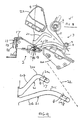
- Figs. 4 to 8 are corresponding side views (taken from the rear side of the document inserting system shown in Fig. 1) of the operating mechanism of the document transporting apparatus, shown in different operating conditions; and
- Fig. 9 is a view on an enlarged scale of a pair of guides included in the apparatus.
-
- Reference is made to the drawings, wherein there is seen in Fig. 1 an elevational view of a tabletop inserter, designated generally at 210, incorporating a
document transporting apparatus 1 forming an embodiment of the invention and associated with an insert feeder 220. It is to be appreciated that reference is made to thedocument transporting apparatus 1 of Fig. 1 only to show an exemplary environment of implementation for this document transporting apparatus. Thus, the inserter 210 is not to be understood to be the only environment for use for thedocument transporting apparatus 1 as one skilled in the art could readily implement the below described document transporting apparatus in various inserter systems requiring a document transporting apparatus or in any other form of mechanism requiring a document transporting apparatus. Therefore, in order not to obscure the description of the document transporting apparatus, only a simplified description of the inserter system 210 depicted in Fig. 1 will be provided. For a more detailed description, reference is made to EP-A-0 700 794, assigned to the present applicants. - With reference to Fig. 1, tabletop inserter 210 generally consists of an
upper housing 212 mounted atop a lower housing 214.Upper housing 212 generally includes first andsecond sheet feeders insert feeders sheet feeder second feed paths 222 and 224. The first andsecond sheet paths 222 and 224 merge with one another at a collation station 226 having first and second collating rollers 229 and 230. The collating station 226 is operative to align the leading edges of first and second sheets being respectively conveyed from the first andsecond sheets feeders second sheet paths 222 and 224, within the nip formed between the collating rollers 228 and 230. Once aligned, the collating rollers 228 and 229 are actuated to simultaneously feed the aligned sheets in asupply path 330 downstream of the collating station 226. These aligned sheets are also known as a "collation". This sheet collation is then conveyed downstream in thesupply path 330 to the folding station 300. - Like conventional folding stations, the folding station is configured to fold the sheet collation in prescribed configurations, such as C-fold, Z-fold, Half-fold, Double-fold etc. In this constructional example, the folding station 300 comprises a first
removable fold plate 302 and a second removable fold plate 304. It includes a diverter which is operable for diverting a sheet approaching thefirst fold plate 302 directly to the second fold plate 304. Depending on the setting of the diverter, the type of fold that is made can be selected. After a collation is folded in the folding station 300, the folded collation is then conveyed to the lower housing 214 of the inserter system 210 for further processing. - The lower housing 214 of inserter system 210 includes an
envelope supply station 240 connecting toinsertion station 20. Theenvelope supply station 240 contains a supply of envelopes stored with their flaps in their closed (but unsealed) condition. These envelopes are fed, with their bottom edges leading and their front panels lowermost, to theinsertion station 120, via envelope feed path 244 preferably. Each envelope flap is opened by a suitable flap opening device while in transit. -Once received in theinsertion station 120, the envelope has its mouth opened in preparation for insertion of the aforesaid folded collation being conveyed from the folding station 300. Thus, the folded collation is transported from the folding station 300 to theinsertion station 120, via a collation transport path 246 connecting the latter two stations. Preferably the collation transport path 246 includes a pair of conveyingrollers 248 and 250 for conveying a folded collation along the transport path 246. - The lower housing 214 further includes a sealing
station 252 located downstream of theinsertion station 120, which sealingstation 252 is operative to seal an open envelope received from theinsertion station 120. An envelope insertion path connects theinsertion station 120 to the sealingstation 252. Anenvelope output path 256 connects to the sealingstation 252 and is operative to convey sealed envelopes from the sealingstation 252 through an output opening 258 provided in the lower housing 214 of the insertion system 210. After a sealed envelope has exited from the output opening 258, appropriate postage can then be applied for delivery to a recipient. - As is conventional, inserter system 210 includes a control system (not shown) for controlling the various components implemented in the inserter system. It is to be appreciated that the control system is to encompass a computer processor driven system.
- With the general structure of inserter system 210 being described above, a more specific description will now be given regarding the document transporting apparatus according to the preferred embodiment.
- Referring firstly to Figure 2, the document transport apparatus, shown generally by
reference numeral 1, comprises a first,movable structure 2 and asecond structure 3, which is secured at respective ends to vertical side walls or plates of the inserter, one of which is shown at 4. - With reference to Figures 2 and 4, the fixed structure comprises a
deflector plate 5, a first pair ofdocument drive rollers 6 mounted ondrive shaft 7, and a second pair of document drive rollers 8 (Figure 4) mounted ondrive shaft 9. - The
movable structure 2 is in the form of a drive carriage comprising a housing having anupper wall 10, abottom wall 11, afront wall 12 and twoopposite side walls 19. A first pair ofidler rollers 13 is rotatably mounted on a first shaft (not shown) and a second pair ofidler rollers 15 is rotatably mounted on a second shaft (also not shown). When thecarriage assembly 2 is in its normal, closed, position shown in Figure 4, theidler rollers document drive rollers rollers - Projecting from each side of the
carriage assembly 2 is a pair of fixedspigots lower guides carriage assembly 2 is provided with apull handle 25 to be gripped by the user for pulling the carriage assembly out from the document transport apparatus. - Also located on each
side wall 4 is a forwardly projecting mountingbracket 22 for receiving the removable insert feed tray (not shown in Figures 2 and 4). In addition, the fixed mount for the removable folding plate 304 is shown at 260. - As shown in Figure 4, an insert sheet fed from the insert feed tray along a path indicated by
arrow 23 enters the nip between drive/drivenrollers deflector plate 5 which deflects it along the surface of the deflector plate until it enters the nip between the drive/drivenrollers sheet feeders arrow 24. - Figure 9 shows on an enlarged scale the configuration of the
guides spigots guides - Each-
guide guide line 22 in Fig. 9. This angle is preferably within therange 5 to 40°, more preferably 10 to 30°, even more preferably about 20°. As a result, with the insert feed tray and fold plate 304 removed from the inserter, the movable carriage can be gripped by the operator, using thehandle 25, and pulled forwardly, so as to cause thespigots document flow path 22, the movable carriage starts to separate from the fixedstructure 3. At the same time, however, thecarriage assembly 2 moves a relatively larger distance in a direction parallel to thedocument transport path 22, taking it beyond themount 260 for the fold plate 304. - Then, the
spigot 17 encounters the curved portion 20c and starts to pivot the carriage assembly away from the fixedstructure 3, as shown in Figure 5, to provide the greatest separation from the fixed structure at the front, or leading, side of the carriage assembly. As the operator pulls the carriage assembly further forward, thespigot 17 passes along the curved guide portion 20c and enters the second guide portion 20b, which is essentially straight and inclined to the insert transport path at an angle greater than , while thespigot 18 starts to pass around the curved guide portion 21c. It will be noted in Figure 9 that the straight guide portion 20b converges on the straight guide portion 21b. This geometry ensures that as the carriage assembly is pulled further forward, its front side swings further away from the fixedstructure 3, thereby increasing the size of the opening or mouth defined between the front edge of the movable carriage assembly and thedeflector plate 5 of the fixed structure 3 (see Figure 6). - Eventually, the
spigot 17 comes to the far or front end of theguide 20, in which the carriage assembly occupies the position shown in Figure 7. This far end of theguide 20 is open, so that on pulling the carriage further forward, the spigot emerges from the open front end of the guide and the carriage assembly can be pulled right out until theother spigot 18 encounters aretainer 23 at the front end of theguide 21, which retaining means holds the carriage assembly captive in the inserter. The arrangement is such that as the carriage assembly is pulled out, its trailing edge can drop down and the leading portion can be raised and rested on an upstanding flange 262 (Figures 1 and 8) on the lower housing 214. The carriage assembly is then supported in a substantially horizontal position. Theretainer 23 prevents the operator from completely removing the carriage assembly from the inserter. In this position (see Figures 3 and 8), the carriage assembly is positioned clear of themount 260 for the fold plate 304, but spaced well away from the fixedstructure 3. It will further be noted that the size of the opening between the movable carriage and the fixedstructure 3 is at a maximum. Therefore, full access is provided for the user to the document transport path through the apparatus, as well as to the forwardly projecting carriage assembly. - From the foregoing description, it will be understood that the described document transport apparatus is of simple construction, and yet is effective in providing wide access to the document transporting path for inspection, servicing, repair and jam clearance. Whilst the apparatus has been described in its intended application for use in association with the feed path of an insert feeder, it will be appreciated that the apparatus can be used in any other document transport path in the inserter, such as on the transport path for the fed sheets, the initial envelope feed path and the sealed envelope feed path. It will further be appreciated that the document transport apparatus can be used not only in an inserter, but also in any form of document handling apparatus, where ready access has to be provided.
- Whilst reference is made hereinabove to stuffing an envelope with a collation, it will be appreciated that the inserter is versatile in operation and can be set so as to feed a single sheet, or a plurality of sheets, with or without folding, in each case with or without one or more inserts. Alternatively, the inserter can be used to place other documents, such as an insert or plurality of inserts only, within the envelope.
Claims (11)
- Apparatus for transporting documents (or the like), comprising first and second structures (2,3) together defining a document transport path (24) and facing respective, opposite, faces of the document when on said path, the first structure being movable relative to the second structure such that, initially, it moves in a direction generally parallel to, or at a shallow angle away from, the document transport path and then it moves laterally with respect to the initial direction, so as to separate said first and second structures and provide access, between said first and second structures, to said path.
- Apparatus according to claim 1, wherein the first structure moves, initially, at a shallow angle (6) away from the second structure, said angle being in the range 5° to 40°.
- Apparatus according to claim 1 or 2, wherein the first structure is a carriage assembly (2) that is movably mounted in at least one guide (20) having a first guide portion (20a) to cause the carriage assembly to undergo its initial movement and a second guide portion (20b) to cause the carriage assembly to undergo its lateral movement.
- Apparatus according to claim 3, wherein in the or each guide (20) is located a spigot (17) on the carriage assembly (2).
- Apparatus according to claim 4, wherein two guides (20,21)are provided at each side of the carriage assembly (2), the guides locating respective spigots (17,18) on the carriage assembly (2), the first guide portions (20a,21a) of the two guides being generally parallel to one another and the second guide portions (20b,21b) converging on one another such that the carriage assembly (2), during its lateral movement, pivots away from the second structure (3) to provide the greatest separation at its leading edge.
- Apparatus according to claim 5, wherein retaining means (23) are provided to prevent the spigot (18) in one of the guides (21) from being withdrawn from the far end of that guide and the other spigot (17) is free to move clear of the far end of the other guide (20) before the spigot of the one guide (21) reaches the far end thereof.
- Apparatus according to any preceding claim, wherein the first and second structures (2,3) carry idler and driven rollers (13,6), respectively, these rollers being in driving contact with one another except when the first structure (2) is moved relative to the second one (3).
- An inserter including an apparatus according to any preceding claim.
- An inserter according to claim 8 as appended, directly or indirectly to claim 6, wherein the carriage assembly (2) is supported on an upstanding flange (262) of the inserter (210) when it is fully withdrawn from the second structure (3).
- An inserter according to claim 8 or 9 and having sheet feeding means (216,218), insert feeding means (220), envelope feeding means (240,244) and means (120) for inserting sheets and inserts into an envelope, wherein the document transporting apparatus is located in the feed path (244) from the insert feeding means (120).
- An inserter according to claim 10 and further comprising insert feeding means (220) having a removable insert feed tray and a mount (22) therefor, and a removable fold plate (304) and mount (260) therefor generally beneath the insert feed tray and its mount, wherein the first structure (2) of the document transporting apparatus is located generally above the removable fold plate mount (260) but, when the removable fold plate is removed from its mount, is moved clear thereof when the first structure (2) is caused to undergo its lateral movement.
Applications Claiming Priority (2)
| Application Number | Priority Date | Filing Date | Title |
|---|---|---|---|
| GBGB9805904.1A GB9805904D0 (en) | 1998-03-19 | 1998-03-19 | Document transporting apparatus |
| GB9805904 | 1998-03-19 |
Publications (2)
| Publication Number | Publication Date |
|---|---|
| EP0943457A1 EP0943457A1 (en) | 1999-09-22 |
| EP0943457B1 true EP0943457B1 (en) | 2003-05-28 |
Family
ID=10828890
Family Applications (1)
| Application Number | Title | Priority Date | Filing Date |
|---|---|---|---|
| EP19990104093 Expired - Fee Related EP0943457B1 (en) | 1998-03-19 | 1999-03-18 | Document transporting apparatus |
Country Status (3)
| Country | Link |
|---|---|
| EP (1) | EP0943457B1 (en) |
| DE (1) | DE69908223D1 (en) |
| GB (1) | GB9805904D0 (en) |
Family Cites Families (5)
| Publication number | Priority date | Publication date | Assignee | Title |
|---|---|---|---|---|
| JPS5821752A (en) * | 1981-07-31 | 1983-02-08 | Fuji Xerox Co Ltd | Jammed paper removing device |
| US4798040A (en) * | 1987-03-25 | 1989-01-17 | Bell & Howell Company | Insertion machine |
| US5081825A (en) * | 1990-12-31 | 1992-01-21 | Pitney Bowes Inc. | Envelope flap unfolder and enclosure inserter with jam-clearing access |
| GB9118581D0 (en) | 1991-08-30 | 1991-10-16 | De La Rue Syst | Sheet transport apparatus |
| GB2292937A (en) | 1994-09-12 | 1996-03-13 | Pitney Bowes Ltd | Sheet-handling apparatus e.g. for mailpieces |
-
1998
- 1998-03-19 GB GBGB9805904.1A patent/GB9805904D0/en not_active Ceased
-
1999
- 1999-03-18 EP EP19990104093 patent/EP0943457B1/en not_active Expired - Fee Related
- 1999-03-18 DE DE69908223T patent/DE69908223D1/en not_active Expired - Lifetime
Also Published As
| Publication number | Publication date |
|---|---|
| EP0943457A1 (en) | 1999-09-22 |
| GB9805904D0 (en) | 1998-05-13 |
| DE69908223D1 (en) | 2003-07-03 |
Similar Documents
| Publication | Publication Date | Title |
|---|---|---|
| EP0943460B1 (en) | Envelope inserting apparatus | |
| EP1016549B1 (en) | Inserter system | |
| US5992132A (en) | Rotating envelope insertion horn | |
| US7427059B2 (en) | Paper handling system materials exit path arrangement | |
| EP2213602A2 (en) | Mailpiece inserter adapted for one-sided operation (OSO) and input conveyor module therefor | |
| US5191751A (en) | Envelope opening apparatus | |
| US5876029A (en) | Feeder assembly apparatus | |
| US4813209A (en) | Single cycle envelope flap opener | |
| EP1935815A2 (en) | Selective drive mechanism | |
| EP1108563B1 (en) | Method for supplying envelopes to an inserter system | |
| US4888938A (en) | Envelope throat opening blade | |
| CA2217547C (en) | Apparatus for accumulating and directionally reorienting sheets | |
| US6164640A (en) | Apparatus for directionally reorienting sheets | |
| EP0943457B1 (en) | Document transporting apparatus | |
| EP1297969B1 (en) | Apparatus and method for collating sheets | |
| US7591454B2 (en) | Paper handling system material feed path arrangement | |
| US5702098A (en) | Envelope closing and sealing apparatus | |
| US6648319B2 (en) | Apparatus for collating sheets | |
| CA2472870C (en) | Apparatus and method for accumulating sheets | |
| EP0943458B1 (en) | Envelope opening apparatus | |
| US7011304B2 (en) | Collator apparatus | |
| CA2037869A1 (en) | Flap opening mechanism and method | |
| EP0943461B1 (en) | An inserter for inserting documents into envelopes | |
| CA2031930C (en) | Envelope opening apparatus | |
| GB2380185A (en) | Sheet folding apparatus and method |
Legal Events
| Date | Code | Title | Description |
|---|---|---|---|
| PUAI | Public reference made under article 153(3) epc to a published international application that has entered the european phase |
Free format text: ORIGINAL CODE: 0009012 |
|
| AK | Designated contracting states |
Kind code of ref document: A1 Designated state(s): DE FR GB |
|
| AX | Request for extension of the european patent |
Free format text: AL;LT;LV;MK;RO;SI |
|
| 17P | Request for examination filed |
Effective date: 20000308 |
|
| AKX | Designation fees paid |
Free format text: DE FR GB |
|
| GRAH | Despatch of communication of intention to grant a patent |
Free format text: ORIGINAL CODE: EPIDOS IGRA |
|
| GRAH | Despatch of communication of intention to grant a patent |
Free format text: ORIGINAL CODE: EPIDOS IGRA |
|
| GRAA | (expected) grant |
Free format text: ORIGINAL CODE: 0009210 |
|
| AK | Designated contracting states |
Designated state(s): DE FR GB |
|
| PG25 | Lapsed in a contracting state [announced via postgrant information from national office to epo] |
Ref country code: FR Free format text: LAPSE BECAUSE OF FAILURE TO SUBMIT A TRANSLATION OF THE DESCRIPTION OR TO PAY THE FEE WITHIN THE PRESCRIBED TIME-LIMIT Effective date: 20030528 |
|
| REG | Reference to a national code |
Ref country code: GB Ref legal event code: FG4D |
|
| REF | Corresponds to: |
Ref document number: 69908223 Country of ref document: DE Date of ref document: 20030703 Kind code of ref document: P |
|
| PG25 | Lapsed in a contracting state [announced via postgrant information from national office to epo] |
Ref country code: DE Free format text: LAPSE BECAUSE OF FAILURE TO SUBMIT A TRANSLATION OF THE DESCRIPTION OR TO PAY THE FEE WITHIN THE PRESCRIBED TIME-LIMIT Effective date: 20030829 |
|
| PG25 | Lapsed in a contracting state [announced via postgrant information from national office to epo] |
Ref country code: GB Free format text: LAPSE BECAUSE OF NON-PAYMENT OF DUE FEES Effective date: 20040318 |
|
| PLBE | No opposition filed within time limit |
Free format text: ORIGINAL CODE: 0009261 |
|
| STAA | Information on the status of an ep patent application or granted ep patent |
Free format text: STATUS: NO OPPOSITION FILED WITHIN TIME LIMIT |
|
| 26N | No opposition filed |
Effective date: 20040302 |
|
| EN | Fr: translation not filed | ||
| GBPC | Gb: european patent ceased through non-payment of renewal fee |
Effective date: 20040318 |