EP0943274B1 - Cooking appliance - Google Patents
Cooking appliance Download PDFInfo
- Publication number
- EP0943274B1 EP0943274B1 EP99301532A EP99301532A EP0943274B1 EP 0943274 B1 EP0943274 B1 EP 0943274B1 EP 99301532 A EP99301532 A EP 99301532A EP 99301532 A EP99301532 A EP 99301532A EP 0943274 B1 EP0943274 B1 EP 0943274B1
- Authority
- EP
- European Patent Office
- Prior art keywords
- cooking appliance
- container arrangement
- appliance according
- apertured member
- heater
- Prior art date
- Legal status (The legal status is an assumption and is not a legal conclusion. Google has not performed a legal analysis and makes no representation as to the accuracy of the status listed.)
- Expired - Lifetime
Links
- 238000010411 cooking Methods 0.000 title claims abstract description 25
- 238000010438 heat treatment Methods 0.000 claims abstract description 13
- 239000000463 material Substances 0.000 claims abstract description 6
- 239000002184 metal Substances 0.000 claims description 17
- 230000002093 peripheral effect Effects 0.000 claims description 13
- 239000000919 ceramic Substances 0.000 claims description 9
- 239000011521 glass Substances 0.000 claims description 4
- 239000002241 glass-ceramic Substances 0.000 claims description 4
- 239000012774 insulation material Substances 0.000 description 2
- 238000002360 preparation method Methods 0.000 description 2
- 239000012772 electrical insulation material Substances 0.000 description 1
- 239000011819 refractory material Substances 0.000 description 1
- 229910001220 stainless steel Inorganic materials 0.000 description 1
- 239000010935 stainless steel Substances 0.000 description 1
Images
Classifications
-
- A—HUMAN NECESSITIES
- A47—FURNITURE; DOMESTIC ARTICLES OR APPLIANCES; COFFEE MILLS; SPICE MILLS; SUCTION CLEANERS IN GENERAL
- A47J—KITCHEN EQUIPMENT; COFFEE MILLS; SPICE MILLS; APPARATUS FOR MAKING BEVERAGES
- A47J36/00—Parts, details or accessories of cooking-vessels
- A47J36/34—Supports for cooking-vessels
-
- A—HUMAN NECESSITIES
- A47—FURNITURE; DOMESTIC ARTICLES OR APPLIANCES; COFFEE MILLS; SPICE MILLS; SUCTION CLEANERS IN GENERAL
- A47J—KITCHEN EQUIPMENT; COFFEE MILLS; SPICE MILLS; APPARATUS FOR MAKING BEVERAGES
- A47J27/00—Cooking-vessels
Definitions
- This invention relates to a cooking appliance comprising a trough-shaped container arrangement formed of frangible material, such as glass, ceramic, or glass-ceramic, provided with at least one electric heater supported underneath.
- the container arrangement is supported and arranged for receiving at least one food item to be thermally processed therein, for example for preparation or cooking.
- the trough-shaped container arrangement may comprise a plurality of containers arranged in side-by-side array, to permit a series of in-line thermal processing operations to be carried out on one or more food items.
- a particular problem with such an appliance is that if during use the trough-shaped container arrangement should break, there is a risk of user contact with one or more hot, electrically live heating elements in the underlying one or more electric heaters.
- a cooking appliance comprising a trough-shaped container arrangement formed of frangible material and supported and arranged for receiving at least one food item to be thermally processed; at least one electric heater supported underneath the container arrangement and incorporating at least one heating element; and at least one apertured member provided between the at least one heater and the underside of the container arrangement and covering the at least one heater, wherein the apertured member is sufficiently strong to remain intact in the event of breakage of the container arrangement and is provided with apertures dimensioned such that a standard finger conforming to European Standard EN60-335 is unable to pass therethrough so as to prevent user contact with the heating element in the heater.
- the at least one apertured member may comprise a metal or a ceramic and when of a metal, may be electrically grounded or earthed.
- the at least one apertured member may comprise a metal mesh, such as of expanded metal form, or a perforated metal or ceramic sheet.
- the at least one apertured member may have a profile substantially corresponding to that of the underside of the container arrangement.
- the at least one heater may be provided with an upstanding peripheral wall, with the at least one apertured member overlying the peripheral wall.
- the apertured member overlying the peripheral wall may contact the underside of the container arrangement and the peripheral wall may have an upper surface profiled to substantially conform to the profile of the underside of the container arrangement.
- the container arrangement may comprise glass, ceramic, or glass-ceramic.
- the trough-shaped container arrangement may comprise a plurality of containers arranged in side-by-side array, to permit a series of in-line thermal processing operations to be carried out on the at least one food item.
- the plurality of containers may be formed individually and assembled to form the container arrangement or may be formed as an integral unit constituting the container arrangement.
- a plurality of electric heaters may be provided.
- a cooking appliance 1 comprises a trough-shaped container arrangement 2, formed of a frangible material, such as glass, ceramic or glass-ceramic and more particularly the latter.
- the arrangement suitably comprises a plurality of containers 3, 4 arranged in side-by-side array.
- the containers 3, 4 may be formed individually and assembled together to form the container arrangement or may be formed as an integral unit constituting the container arrangement.
- the container arrangement is supported with the containers 3, 4 arranged for receiving at least one food item to be thermally processed therein such as for preparation or cooking.
- a series of in-line thermal processing operations is able to be carried out on the one or more food items by treating in one container 3 and then transferring into the next container 4, and so on.
- the container arrangement is heated by means of one or more electric heaters 5 supported underneath it.
- a single heater may be provided extending substantially along the entire length of the container arrangement, or two or more such heaters may be arranged side by side with each extending substantially along the entire length of the container arrangement.
- a plurality of heaters may be provided and arranged such that one or more separate heaters is or are provided under each container 3, 4 of the arrangement.
- the or each heater 5 comprises a metal support tray or dish 6 containing a base layer 7 of thermal and electrical insulation material, which is preferably microporous thermal insulation material of well known form.
- At least one electrical heating element 8 is provided on or adjacent to the base layer 7 and comprises any of the well known forms, such as wire, ribbon or lamp forms.
- the at least one electrical heating element 8 may particularly comprise a corrugated ribbon supported edgewise on the base layer 7 and secured by partial embedding therein.
- a peripheral wall 9 of thermal insulation material is provided in the or each heater 5.
- the peripheral wall 9 has an upper surface 10 profiled to conform substantially to the profile of the underside of the container arrangement.
- thermal limiter (not shown) is provided on the or each heater 5.
- At least one apertured member 11 is provided between the or each heater 5 and the underside of the container arrangement 2 and is constructed so as to remain intact in the event of breakage of the container arrangement and to prevent contact by a user with the heating element or elements 8.
- the apertured member 11 is arranged to cover its associated heater 5, in contact with the upper surface 10 of the peripheral wall 9 and the underside of the container arrangement 2 and is preferably arranged to have a profile substantially corresponding to that of the underside of the container arrangement 2.
- Such apertured member is preferably provided with apertures dimensioned such that a standard finger conforming to European Standard EN60-335 is unable to pass through the apertures therein to contact the heating element or elements 8.
- the apertured member 11 suitably comprises a metal, such as a stainless steel, and may be in the form of a metal mesh, such as of expanded metal form, or a perforated metal sheet.
- the apertured member comprises a metal
- it is preferably electrically connected to ground or earth in the interests of electrical safety.
- the apertured member 11 is provided covering substantially the entire underside of the container arrangement 2. This is not essential. Instead, the apertured member 11 could be provided covering only the upper surface of the heater 5 and secured in contact with the upper surface of the peripheral wall 9.
Landscapes
- Engineering & Computer Science (AREA)
- Food Science & Technology (AREA)
- Cookers (AREA)
- Control And Other Processes For Unpacking Of Materials (AREA)
- General Preparation And Processing Of Foods (AREA)
- Vending Machines For Individual Products (AREA)
- Electric Stoves And Ranges (AREA)
Abstract
Description
- This invention relates to a cooking appliance comprising a trough-shaped container arrangement formed of frangible material, such as glass, ceramic, or glass-ceramic, provided with at least one electric heater supported underneath. The container arrangement is supported and arranged for receiving at least one food item to be thermally processed therein, for example for preparation or cooking.
- The trough-shaped container arrangement may comprise a plurality of containers arranged in side-by-side array, to permit a series of in-line thermal processing operations to be carried out on one or more food items.
- A particular problem with such an appliance is that if during use the trough-shaped container arrangement should break, there is a risk of user contact with one or more hot, electrically live heating elements in the underlying one or more electric heaters.
- It is known from DE-C-196 00 322 (cf. preamble of claim 1) to support a cooking utensil, such as a wok, in a recess in a cooker, the cooking utensil being further supported by means of an apertured plate which is mounted above the cooker and through which the base of the cooking utensil protrudes.
- It is an object of the present invention to overcome or minimise the risk of user contact with one or more hot, electrically live heating elements in the underlying one or more electric heaters.
- According to the present invention there is provided a cooking appliance comprising a trough-shaped container arrangement formed of frangible material and supported and arranged for receiving at least one food item to be thermally processed; at least one electric heater supported underneath the container arrangement and incorporating at least one heating element; and at least one apertured member provided between the at least one heater and the underside of the container arrangement and covering the at least one heater, wherein the apertured member is sufficiently strong to remain intact in the event of breakage of the container arrangement and is provided with apertures dimensioned such that a standard finger conforming to European Standard EN60-335 is unable to pass therethrough so as to prevent user contact with the heating element in the heater.
- The at least one apertured member may comprise a metal or a ceramic and when of a metal, may be electrically grounded or earthed. The at least one apertured member may comprise a metal mesh, such as of expanded metal form, or a perforated metal or ceramic sheet.
- The at least one apertured member may have a profile substantially corresponding to that of the underside of the container arrangement.
- The at least one heater may be provided with an upstanding peripheral wall, with the at least one apertured member overlying the peripheral wall. The apertured member overlying the peripheral wall may contact the underside of the container arrangement and the peripheral wall may have an upper surface profiled to substantially conform to the profile of the underside of the container arrangement.
- The container arrangement may comprise glass, ceramic, or glass-ceramic.
- The trough-shaped container arrangement may comprise a plurality of containers arranged in side-by-side array, to permit a series of in-line thermal processing operations to be carried out on the at least one food item. The plurality of containers may be formed individually and assembled to form the container arrangement or may be formed as an integral unit constituting the container arrangement.
- A plurality of electric heaters may be provided.
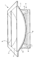
- The invention is now described by way of example with reference to the accompanying drawing which is a sectional view of a cooking appliance according to the invention.
- A cooking appliance 1 comprises a trough-
shaped container arrangement 2, formed of a frangible material, such as glass, ceramic or glass-ceramic and more particularly the latter. The arrangement suitably comprises a plurality ofcontainers containers - The container arrangement is supported with the
containers container 3 and then transferring into thenext container 4, and so on. - The container arrangement is heated by means of one or more electric heaters 5 supported underneath it. A single heater may be provided extending substantially along the entire length of the container arrangement, or two or more such heaters may be arranged side by side with each extending substantially along the entire length of the container arrangement.
- Alternatively, a plurality of heaters may be provided and arranged such that one or more separate heaters is or are provided under each
container - The or each heater 5 comprises a metal support tray or dish 6 containing a base layer 7 of thermal and electrical insulation material, which is preferably microporous thermal insulation material of well known form. At least one electrical heating element 8 is provided on or adjacent to the base layer 7 and comprises any of the well known forms, such as wire, ribbon or lamp forms. The at least one electrical heating element 8 may particularly comprise a corrugated ribbon supported edgewise on the base layer 7 and secured by partial embedding therein.
- A peripheral wall 9 of thermal insulation material is provided in the or each heater 5. The peripheral wall 9 has an upper surface 10 profiled to conform substantially to the profile of the underside of the container arrangement.
- A well-known form of thermal limiter (not shown) is provided on the or each heater 5.
- If the or each heater 5 were to be supported with the upper surface 10 of the peripheral wall in contact with the underside of the
container arrangement 2 and energised for carrying out a thermal processing operation on one or more food items located in thecontainer container arrangement 2 were to occur, the hot and electrically live heating element or elements 8 would become exposed and liable to be contacted by a user of the appliance. In order to avoid this, while maintaining operating efficiency of the heater, at least one apertured member 11 is provided between the or each heater 5 and the underside of thecontainer arrangement 2 and is constructed so as to remain intact in the event of breakage of the container arrangement and to prevent contact by a user with the heating element or elements 8. The apertured member 11 is arranged to cover its associated heater 5, in contact with the upper surface 10 of the peripheral wall 9 and the underside of thecontainer arrangement 2 and is preferably arranged to have a profile substantially corresponding to that of the underside of thecontainer arrangement 2. Such apertured member is preferably provided with apertures dimensioned such that a standard finger conforming to European Standard EN60-335 is unable to pass through the apertures therein to contact the heating element or elements 8. The apertured member 11 suitably comprises a metal, such as a stainless steel, and may be in the form of a metal mesh, such as of expanded metal form, or a perforated metal sheet. It could however comprise another suitably refractory material, such as in the form of a perforated ceramic sheet, provided the material thereof is sufficiently strong for the member to remain intact in event of breakage of thecontainer arrangement 2 and is able to be profiled to match the underside of the container arrangement, if required. - When the apertured member comprises a metal, it is preferably electrically connected to ground or earth in the interests of electrical safety.
- As shown in the accompanying drawing, the apertured member 11 is provided covering substantially the entire underside of the
container arrangement 2. This is not essential. Instead, the apertured member 11 could be provided covering only the upper surface of the heater 5 and secured in contact with the upper surface of the peripheral wall 9.
Claims (14)
- A cooking appliance comprising a trough-shaped container arrangement (2) formed of frangible material and supported and arranged for receiving at least one food item to be thermally processed; at least one electric heater (5) supported underneath the container arrangement and incorporating at least one heating element (8); and at least one apertured member (11) provided between the at least one heater and the underside of the container arrangement and covering the at least one heater characterised in that the apertured member (11) is sufficiently strong to remain intact in the event of breakage of the container arrangement (2) and is provided with apertures dimensioned such that a standard finger conforming to European Standard EN60-335 is unable to pass therethrough so as to prevent user contact with the heating element (8) in the heater (5).
- A cooking appliance according to claim 1, characterised in that the at least one apertured member (11) comprises a metal or a ceramic.
- A cooking appliance according to claim 2, characterised in that the at least one apertured member (11) is of a metal and is electrically grounded or earthed.
- A cooking appliance according to claim 2 or 3, characterised in that the at least one apertured member (11) comprises a metal mesh or a perforated metal or ceramic sheet.
- A cooking appliance according to claim 4, characterised in that the metal mesh is of expanded metal form.
- A cooking appliance according to any preceding claim, characterised in that the at least one apertured member (11) has a profile substantially corresponding to that of the underside of the container arrangement (2).
- A cooking appliance according to any preceding claim, characterised in that the at least one heater (5) is provided with an upstanding peripheral wall (9) and the at least one apertured member (11) overlies the peripheral wall.
- A cooking appliance according to claim 7, characterised in that the apertured member (11) overlying the peripheral wall (9) contacts the underside of the container arrangement (2).
- A cooking appliance according to claim 8, characterised in that the peripheral wall (9) has an upper surface profiled to conform substantially to the profile of the underside of the container arrangement (2).
- A cooking appliance according to any preceding claim, characterised in that the container arrangement (2) comprises glass, ceramic, or glass-ceramic.
- A cooking appliance according to any preceding claim, characterised in that the trough-shaped container arrangement (2) comprises a plurality of containers (3, 4) arranged in side-by-side array, to permit a series of in-line thermal processing operations to be carried out on the at least one food item.
- A cooking appliance according to claim 11, characterised in that the plurality of containers (3, 4) are formed individually and assembled to form the container arrangement (2).
- A cooking appliance according to claim 11, characterised in that the plurality of containers (3, 4) are formed as an integral unit constituting the container arrangement (2).
- A cooking appliance according to any preceding claim, characterised in that a plurality of electric heaters (5) are provided.
Applications Claiming Priority (2)
| Application Number | Priority Date | Filing Date | Title |
|---|---|---|---|
| GB9805420A GB2335137B (en) | 1998-03-14 | 1998-03-14 | Cooking appliance |
| GB9805420 | 1998-03-14 |
Publications (2)
| Publication Number | Publication Date |
|---|---|
| EP0943274A1 EP0943274A1 (en) | 1999-09-22 |
| EP0943274B1 true EP0943274B1 (en) | 2001-01-10 |
Family
ID=10828527
Family Applications (1)
| Application Number | Title | Priority Date | Filing Date |
|---|---|---|---|
| EP99301532A Expired - Lifetime EP0943274B1 (en) | 1998-03-14 | 1999-03-02 | Cooking appliance |
Country Status (5)
| Country | Link |
|---|---|
| US (1) | US6119583A (en) |
| EP (1) | EP0943274B1 (en) |
| AT (1) | ATE198536T1 (en) |
| DE (1) | DE69900046T2 (en) |
| GB (1) | GB2335137B (en) |
Families Citing this family (4)
| Publication number | Priority date | Publication date | Assignee | Title |
|---|---|---|---|---|
| DE19961245A1 (en) * | 1999-12-18 | 2001-07-12 | Schott Glas | Cooking equipment |
| DE10231322B4 (en) * | 2002-07-11 | 2005-11-24 | Schott Ag | Wok bowl made of glass ceramic |
| US8740210B2 (en) * | 2012-07-19 | 2014-06-03 | Gary Fiala | Elevated cutting board apparatus for reducing fat in pan-cooked foods |
| US20150108325A1 (en) * | 2013-10-23 | 2015-04-23 | Keith Ryan | Method and apparatus for electrically-heated refractory moulds and mandrels |
Family Cites Families (19)
| Publication number | Priority date | Publication date | Assignee | Title |
|---|---|---|---|---|
| US3797375A (en) * | 1972-03-16 | 1974-03-19 | Jenn Air Corp | Stove with selectively interchangeable cooking apparatus |
| US3987719A (en) * | 1973-07-23 | 1976-10-26 | Leonard Kian | Cooking utensil |
| US3987275A (en) * | 1976-02-02 | 1976-10-19 | General Electric Company | Glass plate surface heating unit with sheathed heater |
| US4196083A (en) * | 1977-04-08 | 1980-04-01 | Koltse John G | Apparatus and method for continuous plating bath treatment system |
| US4607613A (en) * | 1984-07-19 | 1986-08-26 | George Toldi | Wok adapter |
| US4865219A (en) * | 1987-04-20 | 1989-09-12 | Logan - Barlow | Serving platter for pizza pan |
| US4889103A (en) * | 1988-01-25 | 1989-12-26 | Joseph Fraioli | Infrared wok heater |
| US4873921A (en) * | 1988-07-14 | 1989-10-17 | Piane Caterers, Inc. | Multiple unit wok apparatus |
| US4943705A (en) * | 1989-05-01 | 1990-07-24 | Halloran Michael R | Tissue warming apparatus |
| US5213027A (en) * | 1991-07-11 | 1993-05-25 | The Alexander Oven Co., Inc. | Barbecue grill assembly |
| US5782172A (en) * | 1992-10-08 | 1998-07-21 | Schacht; Paul | Appliance for low and high-heat cooking |
| FR2716101B1 (en) * | 1994-02-15 | 1996-04-26 | Seb Sa | Culinary container with reinforced bottom and its manufacturing process. |
| US5687642A (en) * | 1995-10-10 | 1997-11-18 | Chao; Nathan | Concave induction cooking surface for wok cooking |
| US5579679A (en) * | 1995-12-20 | 1996-12-03 | Lundar Electric Industrial Co., Ltd. | Roaster |
| DE19600322C1 (en) * | 1996-01-08 | 1997-07-31 | Neubauer Kurt Maschf | Holder for curved wok-type cooking pans over cooker level |
| US5868063A (en) * | 1997-04-25 | 1999-02-09 | Longmuir; Robert William | Corn steamer device |
| JP2001500044A (en) * | 1997-06-23 | 2001-01-09 | コーニンクレッカ フィリップス エレクトロニクス エヌ ヴィ | Kitchen appliance having a drive unit disposed on a container |
| US5850779A (en) * | 1997-11-03 | 1998-12-22 | Zimmerman; John A. R. | Pan tilting apparatus |
| US5943949A (en) * | 1998-04-30 | 1999-08-31 | Wing Shing Products (Bvi) Co., Ltd. | Indoor grille |
-
1998
- 1998-03-14 GB GB9805420A patent/GB2335137B/en not_active Expired - Fee Related
-
1999
- 1999-03-02 EP EP99301532A patent/EP0943274B1/en not_active Expired - Lifetime
- 1999-03-02 DE DE69900046T patent/DE69900046T2/en not_active Expired - Fee Related
- 1999-03-02 AT AT99301532T patent/ATE198536T1/en not_active IP Right Cessation
- 1999-03-04 US US09/262,539 patent/US6119583A/en not_active Expired - Fee Related
Also Published As
| Publication number | Publication date |
|---|---|
| GB9805420D0 (en) | 1998-05-06 |
| DE69900046D1 (en) | 2001-02-15 |
| EP0943274A1 (en) | 1999-09-22 |
| US6119583A (en) | 2000-09-19 |
| DE69900046T2 (en) | 2001-06-21 |
| GB2335137B (en) | 2002-06-05 |
| GB2335137A (en) | 1999-09-15 |
| ATE198536T1 (en) | 2001-01-15 |
Similar Documents
| Publication | Publication Date | Title |
|---|---|---|
| US4327280A (en) | Smooth top cookers | |
| US5374807A (en) | Domestic cooking apparatus | |
| US4393299A (en) | Electric radiant heater unit for a glass ceramic top cooker | |
| US4430558A (en) | Electric radiant heater unit for a glass ceramic top cooker | |
| EP0918448B1 (en) | Radiant electric heater | |
| US6323472B1 (en) | Radiant electric heater for a microwave oven | |
| EP0943274B1 (en) | Cooking appliance | |
| US7057139B2 (en) | Electric heating assembly | |
| US5517002A (en) | Radiant electric heater | |
| US6043463A (en) | Electric heater | |
| GB2087698A (en) | Electric radiant heater unit | |
| EP0981263B1 (en) | Radiant electric heater | |
| WO1994024490A1 (en) | A hob | |
| EP1380190B1 (en) | Radiant electric heater | |
| EP0973356A2 (en) | Radiant electric heater | |
| GB2170590A (en) | Cooking apparatus | |
| KR200413260Y1 (en) | Radiant electric heater | |
| US20040065654A1 (en) | Oven with cavity having turntable and heater | |
| EP0932326A2 (en) | Radiant electric heater | |
| WO2002039020A2 (en) | Oven with cavity having turntable and heater | |
| WO2004066682A1 (en) | Radiant electric heater | |
| WO2009053674A1 (en) | Radiant electric heater |
Legal Events
| Date | Code | Title | Description |
|---|---|---|---|
| PUAI | Public reference made under article 153(3) epc to a published international application that has entered the european phase |
Free format text: ORIGINAL CODE: 0009012 |
|
| AK | Designated contracting states |
Kind code of ref document: A1 Designated state(s): AT BE CH DE DK ES FR GR IT LI NL PT SE |
|
| AX | Request for extension of the european patent |
Free format text: AL;LT;LV;MK;RO;SI |
|
| 17P | Request for examination filed |
Effective date: 19991001 |
|
| 17Q | First examination report despatched |
Effective date: 20000207 |
|
| GRAG | Despatch of communication of intention to grant |
Free format text: ORIGINAL CODE: EPIDOS AGRA |
|
| AKX | Designation fees paid |
Free format text: AT BE CH DE DK ES FR GB GR IT LI NL PT SE |
|
| GRAG | Despatch of communication of intention to grant |
Free format text: ORIGINAL CODE: EPIDOS AGRA |
|
| GRAH | Despatch of communication of intention to grant a patent |
Free format text: ORIGINAL CODE: EPIDOS IGRA |
|
| GRAH | Despatch of communication of intention to grant a patent |
Free format text: ORIGINAL CODE: EPIDOS IGRA |
|
| RBV | Designated contracting states (corrected) |
Designated state(s): AT BE CH DE DK ES FR GR IT LI NL PT SE |
|
| GRAA | (expected) grant |
Free format text: ORIGINAL CODE: 0009210 |
|
| AK | Designated contracting states |
Kind code of ref document: B1 Designated state(s): AT BE CH DE DK ES FR GR IT LI NL PT SE |
|
| PG25 | Lapsed in a contracting state [announced via postgrant information from national office to epo] |
Ref country code: SE Free format text: THE PATENT HAS BEEN ANNULLED BY A DECISION OF A NATIONAL AUTHORITY Effective date: 20010110 Ref country code: NL Free format text: LAPSE BECAUSE OF FAILURE TO SUBMIT A TRANSLATION OF THE DESCRIPTION OR TO PAY THE FEE WITHIN THE PRESCRIBED TIME-LIMIT Effective date: 20010110 Ref country code: LI Free format text: LAPSE BECAUSE OF FAILURE TO SUBMIT A TRANSLATION OF THE DESCRIPTION OR TO PAY THE FEE WITHIN THE PRESCRIBED TIME-LIMIT Effective date: 20010110 Ref country code: IT Free format text: LAPSE BECAUSE OF FAILURE TO SUBMIT A TRANSLATION OF THE DESCRIPTION OR TO PAY THE FEE WITHIN THE PRESCRIBED TIME-LIMIT;WARNING: LAPSES OF ITALIAN PATENTS WITH EFFECTIVE DATE BEFORE 2007 MAY HAVE OCCURRED AT ANY TIME BEFORE 2007. THE CORRECT EFFECTIVE DATE MAY BE DIFFERENT FROM THE ONE RECORDED. Effective date: 20010110 Ref country code: FR Free format text: LAPSE BECAUSE OF FAILURE TO SUBMIT A TRANSLATION OF THE DESCRIPTION OR TO PAY THE FEE WITHIN THE PRESCRIBED TIME-LIMIT Effective date: 20010110 Ref country code: CH Free format text: LAPSE BECAUSE OF FAILURE TO SUBMIT A TRANSLATION OF THE DESCRIPTION OR TO PAY THE FEE WITHIN THE PRESCRIBED TIME-LIMIT Effective date: 20010110 Ref country code: BE Free format text: LAPSE BECAUSE OF FAILURE TO SUBMIT A TRANSLATION OF THE DESCRIPTION OR TO PAY THE FEE WITHIN THE PRESCRIBED TIME-LIMIT Effective date: 20010110 Ref country code: AT Free format text: LAPSE BECAUSE OF FAILURE TO SUBMIT A TRANSLATION OF THE DESCRIPTION OR TO PAY THE FEE WITHIN THE PRESCRIBED TIME-LIMIT Effective date: 20010110 |
|
| REF | Corresponds to: |
Ref document number: 198536 Country of ref document: AT Date of ref document: 20010115 Kind code of ref document: T |
|
| REG | Reference to a national code |
Ref country code: CH Ref legal event code: EP |
|
| REF | Corresponds to: |
Ref document number: 69900046 Country of ref document: DE Date of ref document: 20010215 |
|
| PG25 | Lapsed in a contracting state [announced via postgrant information from national office to epo] |
Ref country code: PT Free format text: LAPSE BECAUSE OF FAILURE TO SUBMIT A TRANSLATION OF THE DESCRIPTION OR TO PAY THE FEE WITHIN THE PRESCRIBED TIME-LIMIT Effective date: 20010410 Ref country code: DK Free format text: LAPSE BECAUSE OF FAILURE TO SUBMIT A TRANSLATION OF THE DESCRIPTION OR TO PAY THE FEE WITHIN THE PRESCRIBED TIME-LIMIT Effective date: 20010410 |
|
| PG25 | Lapsed in a contracting state [announced via postgrant information from national office to epo] |
Ref country code: GR Free format text: LAPSE BECAUSE OF FAILURE TO SUBMIT A TRANSLATION OF THE DESCRIPTION OR TO PAY THE FEE WITHIN THE PRESCRIBED TIME-LIMIT Effective date: 20010413 |
|
| NLV1 | Nl: lapsed or annulled due to failure to fulfill the requirements of art. 29p and 29m of the patents act | ||
| EN | Fr: translation not filed | ||
| REG | Reference to a national code |
Ref country code: CH Ref legal event code: PL |
|
| PG25 | Lapsed in a contracting state [announced via postgrant information from national office to epo] |
Ref country code: ES Free format text: LAPSE BECAUSE OF FAILURE TO SUBMIT A TRANSLATION OF THE DESCRIPTION OR TO PAY THE FEE WITHIN THE PRESCRIBED TIME-LIMIT Effective date: 20010725 |
|
| PLBE | No opposition filed within time limit |
Free format text: ORIGINAL CODE: 0009261 |
|
| STAA | Information on the status of an ep patent application or granted ep patent |
Free format text: STATUS: NO OPPOSITION FILED WITHIN TIME LIMIT |
|
| 26N | No opposition filed | ||
| PGFP | Annual fee paid to national office [announced via postgrant information from national office to epo] |
Ref country code: DE Payment date: 20050223 Year of fee payment: 7 |
|
| PG25 | Lapsed in a contracting state [announced via postgrant information from national office to epo] |
Ref country code: DE Free format text: LAPSE BECAUSE OF NON-PAYMENT OF DUE FEES Effective date: 20061003 |