EP0942634B1 - HID head-lamp device for a vehicle - Google Patents
HID head-lamp device for a vehicle Download PDFInfo
- Publication number
- EP0942634B1 EP0942634B1 EP19990104596 EP99104596A EP0942634B1 EP 0942634 B1 EP0942634 B1 EP 0942634B1 EP 19990104596 EP19990104596 EP 19990104596 EP 99104596 A EP99104596 A EP 99104596A EP 0942634 B1 EP0942634 B1 EP 0942634B1
- Authority
- EP
- European Patent Office
- Prior art keywords
- lamp
- hid
- lighting
- unit
- voltage
- Prior art date
- Legal status (The legal status is an assumption and is not a legal conclusion. Google has not performed a legal analysis and makes no representation as to the accuracy of the status listed.)
- Expired - Lifetime
Links
- 239000011347 resin Substances 0.000 claims description 7
- 229920005989 resin Polymers 0.000 claims description 7
- 239000007787 solid Substances 0.000 claims description 6
- 238000010276 construction Methods 0.000 description 2
- 230000007547 defect Effects 0.000 description 2
- 238000010586 diagram Methods 0.000 description 2
- 239000003990 capacitor Substances 0.000 description 1
- 230000002950 deficient Effects 0.000 description 1
- 230000000694 effects Effects 0.000 description 1
- 238000010304 firing Methods 0.000 description 1
- 239000000463 material Substances 0.000 description 1
- 230000002093 peripheral effect Effects 0.000 description 1
- 238000004382 potting Methods 0.000 description 1
Images




Classifications
-
- H—ELECTRICITY
- H05—ELECTRIC TECHNIQUES NOT OTHERWISE PROVIDED FOR
- H05B—ELECTRIC HEATING; ELECTRIC LIGHT SOURCES NOT OTHERWISE PROVIDED FOR; CIRCUIT ARRANGEMENTS FOR ELECTRIC LIGHT SOURCES, IN GENERAL
- H05B41/00—Circuit arrangements or apparatus for igniting or operating discharge lamps
- H05B41/02—Details
- H05B41/04—Starting switches
- H05B41/042—Starting switches using semiconductor devices
Definitions
- the present invention relates to an HID (High Intensity Discharge) head lamp device using HID lamps as headlights of a vehicle.
- HID High Intensity Discharge
- FIG. 12 there is shown a conventional arrangement for using an HID lamp as a headlight of a vehicle is shown in Fig. 12, wherein an HID lamp socket 4 is provided in a lamp-mounting place of the vehicle and a single solid lamp-lighting unit 5, which is formed by potting a printed circuit board with a DC-DC converter, a control circuit, a lamp lighting circuit, a high-voltage generating transformer in a housing with insulating resin material poured in melted state and solidified therein, is separately mounted in a bonnet of the vehicle, then the lamp-lighting unit 5 is connected to the lamp socket by using a high-voltage cable 6 and a low-voltage cable 7.
- Two HID head-lamp devices each composed of the lamp lighting unit 5 with the socket 4 are separately mounted left and right on the front of the vehicle.
- Fig. 13 shows a typical circuit configuration of a HID lamp lighting unit 5.
- An HID head lamp LP fitted in a socket 4 connected to a secondary side of a high-voltage generating transformer 3 is fired by a high voltage (about 25 KV) generated at the secondary coil of the transformer 3 by applying a starting voltage to a lamp lighting circuit 2 (with a switch circuit 21 being ON) under the control of a control circuit (ECU) 1 when a lighting switch SW is turned on.
- ECU control circuit
- the switch circuit portion 21 is turned off and the maintaining voltage is applied to the secondary coil of the transformer 3 to maintain the lighting of the lamp LP.
- BAT designates a battery mounted in a vehicle and numeral 8 denotes a DC-DC converter.
- the above-described conventional HID head lamp device consisting of a lamp socket 4 and a lamp lighting unit 5 and mounted left or right on the front portion of a vehicle requires replacement of the entire unit 5 if any trouble occurs with its internal component such as an ECU and any circuit element or an internal circuit.
- the device requires separate arrangement of the lamp socket apart from the lamp lighting unit and interconnection of them by using a high-voltage cable 6 and a low-voltage cable 7. This complicates the mounting work of the unit. Furthermore, the use of elongated high-voltage cable may be associated with the risk of a leak current therefrom, which may cause reduction of the output voltage of the discharge lamp unit and affect the other peripheral electrical devices.
- EP-0596806-A1 shows a HID (high intensity discharge) head lamp device for a vehicle according to the preamble part of claim 1. Furthermore, EP-0739154-A1 discloses a HID head lamp device to be used in connection with an alternating current supply means which employs an autotransformer for applying a starting voltage and a maintaining voltage via separate cables to the HID lamp.
- an object of the present invention is to provide an HID head lamp device that is compact, easy to mount and easy to repair, when any trouble occurs with an ECU or a circuit element or a circuit of the device, by replacing only a defective one of the components.
- This device comprises, therefore, two separately mountable head-lamp units each of which is a single solid unit having a lamp socket fitted thereon and a head-lamp lighting circuit with a transformer potted therein with insulating resin poured in a melted state and solidified therein, a separate control circuit (ECU) with a DC-DC converter, which is commonly used for control of two head-lamp units mounted left and right on a front portion of the vehicle.
- ECU separate control circuit
- DC-DC converter which is commonly used for control of two head-lamp units mounted left and right on a front portion of the vehicle.
- an HID head lamp device comprises a pair of head lamp units 9 each of which is a single solid unit in which a lamp lighting circuit 2, a transformer 3 and a lamp socket 4 for an HID lamp LP are potted therein with insulating resin poured in a melted state and solidified therein, and a control circuit (ECU) 1 provided with a lighting switch SW and a DC-DC converter 8, which circuit can control both the left and right head lamp units 91 and 92 connected in parallel thereto.
- ECU control circuit
- the device thus uses a single control circuit 1 and a single DC-DC converter 8 in common for the left and right head-lamp units, realizing saving in the number of parts and improving a space factor when it is mounted in the vehicle.
- the device in which a failure arose can be repaired by locating a defect in device and by partly replacing the fault-related component among the control circuit 1, the DC-DC converter and the head lamp units 91 and 92.
- the head lamp unit 9 has the lamp socket 4 integrally formed thereon and, therefore, can be mounted with no need for laying an elongated high-voltage cable between the socket and the head lamp unit.
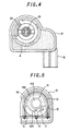
- the head lamp unit 9 is constructed by way of example as shown in Figs. 2 to 5.
- a coil case 12 has three conducting plates 13 insert-formed on the periphery thereof and an HID lamp socket 4 coaxially formed thereon and accommodates therein a secondary coil unit 14 inserted in such a way that its output terminal is electrically connected with a terminal of the socket 4.
- the coil case 12 with the secondary coil unit 14 is then mounted on a printed circuit board 15 which has a circuit pattern of a lamp lighting circuit (2) with circuit elements previously mounted thereon, which circuit is completed with the coil case 12 with the secondary coil unit 14 incorporated therein.
- the printed circuit board 15 also has a circuit pattern of a primary coil circuit to be completed by connecting in series thereto the three conducting plates 13 of the coil case 12.
- An assembly consisting of the coil case 12, the secondary coil unit 14 and the printed circuit board 15 is then mounted in a housing 17 having a power supply socket 18 integrally formed thereon in such a way that the top of the lamp socket 4 projects from the housing and the primary coil input terminal is electrically connected with the power-supply socket terminal. All of the inside components are then potted in the housing 17 with insulating resin poured in a melted state and solidified therein to form a single solid unit.
- a coil case 12 with an HID lamp socket coaxially fitted thereon is illustrated in Figs. 7 to 9.
- the coil case 12 has an opening formed in its bottom for inserting therein a secondary coil unit 14. Terminal pins 131 of the respective conducting plates insert-formed on the periphery of the coil case 12 are projecting from the bottom of the coil case 12.
- the coil case 12 is mounted at a designated place on the printed circuit board 15 in such a way that the terminal pins are inserted into corresponding holes 151 provided in the printed board 15 and bonded therein.
- the conducting plates 13 are in series connected on the circuit pattern 152 previously formed on the printed circuit board 15 to complete a primary coil circuit as shown in Fig. 11.
- the HID lamp socket 4 has a high voltage terminal 19 disposed at its center portion and a low voltage terminal 20 disposed near thereto.
- the secondary coil unit 14 consists of a bobbin 142 having a secondary coil 141 wound thereon and a core 143 inserted in a hollow center thereof.
- the coil bobbin 142 has an end flange 421 with an input electrode 11 to which the starting end of the secondary coil 141 connected.
- the coil case 12 is mounted at the designated place on the printed circuit board 15 in such a way that a terminal pin 111 of the input electrode 11 is inserted in a hole 115 provided in the printed circuit board 15.
- the terminal pins are bonded therein and connected thereby with the input voltage line +E (see Fig. 5).
- the coil bobbin 142 also has the other end flange 422 with an output electrode 112 to which the end of the secondary coil 141 connected.
- a terminal pin 111 of the output electrode 11 becomes in contact with a rear-end portion 191 of the high-voltage terminal 19 in the socket 4, which portion projects into the coil case 12 (Fig. 6).
- the secondary coil unit 14 is then integrally potted in the coil case 12 with insulating resin poured in a melted state and solidified therein.
- Figs. 10 and 11 are illustrative of a printed circuit board 15 to be implemented with a discharge lamp.
- the printed circuit board 15 is provided with the coil case 12 incorporating the secondary coil unit 14 on the top surface (Fig. 10) and is also implemented at the same surface with circuit elements 16 such as switching elements and capacitors on the same surface.
- the printed circuit board 15 is also implemented with circuit elements 16 such as resistance and diodes on the bottom surface (Fig. 11). These circuit elements interconnected by the wiring pattern formed on the printed circuit board to form thereon a lamp lighting circuit 16 as shown in Fig. 13.
- the printed circuit board 15 has paired holes 154 and 155 made therein for a grounding (GND) terminal and a driving voltage (+E) terminal respectively.
- GND grounding
- (+E driving voltage
- a high voltage necessary for lighting an HID head lamp LP is generated by the transformer 3 but it may not affect the circuit elements 16 on the printed circuit board 15 disposed near the coil case 12 owing to a shielding effect of the conducting plates 13 provided on the periphery of the coil case 12.
- the output terminal of the secondary coil 141 can be directly connected to the high-voltage terminal 19 of the socket 4 with no need of additional high-voltage wiring onto the printed circuit board and laying a high-voltage cable.
- the unit thus realizes the simple and optimal connection of its high-voltage portion.
- a compact HID-lamp lighting circuit is formed when the high-voltage generating transformer 3 composed of the secondary coil unit 14 inserted in the coil case 12 is simply mounted at the designated place on the printed circuit board.
- the board 15 is simply mounted in the housing 12, by which the electrical connection between the printed circuit board 15 and the power-supply socket portion 18 provided on the housing 12 is completed with no need of doing any additional wiring work.
- the head lamp unit 9 thus assembled is compact and can be directly mounted in a limited space of a headlight mounting portion of the vehicle.
- This unit is easy to assemble since it requires only connection of a power source to the power-supply socket portion 18 thereof, thus eliminating the need of using an elongated high-voltage cable.
- the HID head lamp device which can drive each of HID headlights by generating a high voltage at a secondary side of a transformer by applying a starting voltage to a lamp lighting circuit under the control of a control circuit when a lighting switch is turned on and can maintain lighting of the HID lamp by applying a maintaining voltage to the secondary side of the transformer after lighting the HID lamp.
- This device comprises left and right head lamp units each having a single solid housing in which a lamp-lighting circuit, a high voltage generating transformer and an HID lamp socket are potted with insulating resin poured in a melted state and solidified therein, and a single control circuit capable of controlling both the left and right head lamp units.
- the HID head lamp device of the present invention is easy to mount in a vehicle and allows the head lamp units and the control circuit to be selectively replaced with new ones in the event the device fails due to a trouble with the control unit (ECU) or the circuit elements in any head lamp unit or damage of circuitry therein.
- ECU control unit
Landscapes
- Lighting Device Outwards From Vehicle And Optical Signal (AREA)
- Non-Portable Lighting Devices Or Systems Thereof (AREA)
- Circuit Arrangements For Discharge Lamps (AREA)
- Arrangement Of Elements, Cooling, Sealing, Or The Like Of Lighting Devices (AREA)
Description
- The present invention relates to an HID (High Intensity Discharge) head lamp device using HID lamps as headlights of a vehicle.
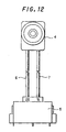
- In Fig. 12, there is shown a conventional arrangement for using an HID lamp as a headlight of a vehicle is shown in Fig. 12, wherein an
HID lamp socket 4 is provided in a lamp-mounting place of the vehicle and a single solid lamp-lighting unit 5, which is formed by potting a printed circuit board with a DC-DC converter, a control circuit, a lamp lighting circuit, a high-voltage generating transformer in a housing with insulating resin material poured in melted state and solidified therein, is separately mounted in a bonnet of the vehicle, then the lamp-lighting unit 5 is connected to the lamp socket by using a high-voltage cable 6 and a low-voltage cable 7. - Two HID head-lamp devices each composed of the
lamp lighting unit 5 with thesocket 4 are separately mounted left and right on the front of the vehicle. - Fig. 13 shows a typical circuit configuration of a HID
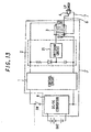
lamp lighting unit 5. An HID head lamp LP fitted in asocket 4 connected to a secondary side of a high-voltage generating transformer 3 is fired by a high voltage (about 25 KV) generated at the secondary coil of the transformer 3 by applying a starting voltage to a lamp lighting circuit 2 (with aswitch circuit 21 being ON) under the control of a control circuit (ECU) 1 when a lighting switch SW is turned on. On completion of firing the HID lamp, theswitch circuit portion 21 is turned off and the maintaining voltage is applied to the secondary coil of the transformer 3 to maintain the lighting of the lamp LP. In Fig. 13, BAT designates a battery mounted in a vehicle and numeral 8 denotes a DC-DC converter. - The above-described conventional HID head lamp device consisting of a
lamp socket 4 and alamp lighting unit 5 and mounted left or right on the front portion of a vehicle requires replacement of theentire unit 5 if any trouble occurs with its internal component such as an ECU and any circuit element or an internal circuit. - The device requires separate arrangement of the lamp socket apart from the lamp lighting unit and interconnection of them by using a high-
voltage cable 6 and a low-voltage cable 7. This complicates the mounting work of the unit. Furthermore, the use of elongated high-voltage cable may be associated with the risk of a leak current therefrom, which may cause reduction of the output voltage of the discharge lamp unit and affect the other peripheral electrical devices. - EP-0596806-A1 shows a HID (high intensity discharge) head lamp device for a vehicle according to the preamble part of claim 1. Furthermore, EP-0739154-A1 discloses a HID head lamp device to be used in connection with an alternating current supply means which employs an autotransformer for applying a starting voltage and a maintaining voltage via separate cables to the HID lamp.
- Accordingly, an object of the present invention, as set forth in claim 1, is to provide an HID head lamp device that is compact, easy to mount and easy to repair, when any trouble occurs with an ECU or a circuit element or a circuit of the device, by replacing only a defective one of the components. This device comprises, therefore, two separately mountable head-lamp units each of which is a single solid unit having a lamp socket fitted thereon and a head-lamp lighting circuit with a transformer potted therein with insulating resin poured in a melted state and solidified therein, a separate control circuit (ECU) with a DC-DC converter, which is commonly used for control of two head-lamp units mounted left and right on a front portion of the vehicle. In the event of a trouble with the device, user can eliminate the defect by replacing only one of the lighting units or the control circuit or the DC-DC converter, which relates to the trouble.
-
- Fig. 1 is an electric circuit diagram of an HID head lamp device embodying the present invention.
- Fig. 2 is a sectional plan view of an exemplified HID head lamp unit of the HID head lamp device of Fig. 1.
- Fig. 3 is a longitudinal sectional view of the HID head lamp unit of Fig. 2.
- Fig. 4 is a front elevation view of the HID head lamp unit of Fig. 2.
- Fig. 5 is a rear end view, partly in cross section, of the HID head lamp unit of Fig. 2.
- Fig. 6 is a front sectional view of the HID head lamp unit of Fig. 2.
- Fig. 7 is a plan view of a coil case of the HID head lamp unit of Fig. 2.
- Fig. 8 is a bottom view of the coil case of Fig. 7. Fig. 9 is front elevation view of the coil case of Fig. 7.
- Fig. 10 is a top view of a printed circuit board of the HID head lamp unit of Fig. 2.
- Fig. 11 is a bottom view of the printed circuit board of Fig. 10.
- Fig. 12 is a front elevation view of a conventional HID head lamp unit disposed on the left or right side of a vehicle.
- Fig. 13 is a typical circuit diagram of an HID lamp lighting system.
-
- The preferred embodiments of the present invention will now be described in detail by way of example and with reference to the accompanying drawings.
- As shown in Fig. 1, an HID head lamp device according to the present invention comprises a pair of head lamp units 9 each of which is a single solid unit in which a
lamp lighting circuit 2, a transformer 3 and alamp socket 4 for an HID lamp LP are potted therein with insulating resin poured in a melted state and solidified therein, and a control circuit (ECU) 1 provided with a lighting switch SW and a DC-DC converter 8, which circuit can control both the left and righthead lamp units - The device thus uses a single control circuit 1 and a single DC-DC converter 8 in common for the left and right head-lamp units, realizing saving in the number of parts and improving a space factor when it is mounted in the vehicle.
- Owing to the construction that the control circuit 1 provided with the DC-DC converter 8 is separated from the separate single-solid-type
head lamp units head lamp units - Furthermore, the head lamp unit 9 has the
lamp socket 4 integrally formed thereon and, therefore, can be mounted with no need for laying an elongated high-voltage cable between the socket and the head lamp unit. - The head lamp unit 9 is constructed by way of example as shown in Figs. 2 to 5.
- A
coil case 12 has three conductingplates 13 insert-formed on the periphery thereof and anHID lamp socket 4 coaxially formed thereon and accommodates therein asecondary coil unit 14 inserted in such a way that its output terminal is electrically connected with a terminal of thesocket 4. Thecoil case 12 with thesecondary coil unit 14 is then mounted on a printedcircuit board 15 which has a circuit pattern of a lamp lighting circuit (2) with circuit elements previously mounted thereon, which circuit is completed with thecoil case 12 with thesecondary coil unit 14 incorporated therein. The printedcircuit board 15 also has a circuit pattern of a primary coil circuit to be completed by connecting in series thereto the three conductingplates 13 of thecoil case 12. An assembly consisting of thecoil case 12, thesecondary coil unit 14 and the printedcircuit board 15 is then mounted in ahousing 17 having apower supply socket 18 integrally formed thereon in such a way that the top of thelamp socket 4 projects from the housing and the primary coil input terminal is electrically connected with the power-supply socket terminal. All of the inside components are then potted in thehousing 17 with insulating resin poured in a melted state and solidified therein to form a single solid unit. - A
coil case 12 with an HID lamp socket coaxially fitted thereon is illustrated in Figs. 7 to 9. - The
coil case 12 has an opening formed in its bottom for inserting therein asecondary coil unit 14.Terminal pins 131 of the respective conducting plates insert-formed on the periphery of thecoil case 12 are projecting from the bottom of thecoil case 12. - The
coil case 12 is mounted at a designated place on the printedcircuit board 15 in such a way that the terminal pins are inserted intocorresponding holes 151 provided in the printedboard 15 and bonded therein. The conductingplates 13 are in series connected on the circuit pattern 152 previously formed on the printedcircuit board 15 to complete a primary coil circuit as shown in Fig. 11. - The
HID lamp socket 4 has ahigh voltage terminal 19 disposed at its center portion and alow voltage terminal 20 disposed near thereto. - The
secondary coil unit 14 consists of abobbin 142 having asecondary coil 141 wound thereon and acore 143 inserted in a hollow center thereof. - The
coil bobbin 142 has anend flange 421 with aninput electrode 11 to which the starting end of thesecondary coil 141 connected. Thecoil case 12 is mounted at the designated place on the printedcircuit board 15 in such a way that aterminal pin 111 of theinput electrode 11 is inserted in a hole 115 provided in the printedcircuit board 15. The terminal pins are bonded therein and connected thereby with the input voltage line +E (see Fig. 5). - The
coil bobbin 142 also has theother end flange 422 with anoutput electrode 112 to which the end of thesecondary coil 141 connected. When thecoil case 12 is mounted at the designated place on the printedcircuit board 15, aterminal pin 111 of theoutput electrode 11 becomes in contact with a rear-end portion 191 of the high-voltage terminal 19 in thesocket 4, which portion projects into the coil case 12 (Fig. 6). Thesecondary coil unit 14 is then integrally potted in thecoil case 12 with insulating resin poured in a melted state and solidified therein. - Figs. 10 and 11 are illustrative of a printed
circuit board 15 to be implemented with a discharge lamp. The printedcircuit board 15 is provided with thecoil case 12 incorporating thesecondary coil unit 14 on the top surface (Fig. 10) and is also implemented at the same surface withcircuit elements 16 such as switching elements and capacitors on the same surface. The printedcircuit board 15 is also implemented withcircuit elements 16 such as resistance and diodes on the bottom surface (Fig. 11). These circuit elements interconnected by the wiring pattern formed on the printed circuit board to form thereon alamp lighting circuit 16 as shown in Fig. 13. - The printed
circuit board 15 has pairedholes circuit board 15 is mounted in thehousing 17 with thepower supply socket 18, rear-side terminal pins power supply socket 18 are fitted incorresponding holes - In the head lamp unit 9, a high voltage necessary for lighting an HID head lamp LP is generated by the transformer 3 but it may not affect the
circuit elements 16 on the printedcircuit board 15 disposed near thecoil case 12 owing to a shielding effect of the conductingplates 13 provided on the periphery of thecoil case 12. - Once the
secondary coil unit 14 is mounted in thecoil case 12 with theHID lamp socket 4 integrally formed therein, the output terminal of thesecondary coil 141 can be directly connected to the high-voltage terminal 19 of thesocket 4 with no need of additional high-voltage wiring onto the printed circuit board and laying a high-voltage cable. The unit thus realizes the simple and optimal connection of its high-voltage portion. - A compact HID-lamp lighting circuit is formed when the high-voltage generating transformer 3 composed of the
secondary coil unit 14 inserted in thecoil case 12 is simply mounted at the designated place on the printed circuit board. Theboard 15 is simply mounted in thehousing 12, by which the electrical connection between the printedcircuit board 15 and the power-supply socket portion 18 provided on thehousing 12 is completed with no need of doing any additional wiring work. - The head lamp unit 9 thus assembled is compact and can be directly mounted in a limited space of a headlight mounting portion of the vehicle. This unit is easy to assemble since it requires only connection of a power source to the power-
supply socket portion 18 thereof, thus eliminating the need of using an elongated high-voltage cable. - As is apparent from the foregoing, the HID head lamp device according to the present invention, which can drive each of HID headlights by generating a high voltage at a secondary side of a transformer by applying a starting voltage to a lamp lighting circuit under the control of a control circuit when a lighting switch is turned on and can maintain lighting of the HID lamp by applying a maintaining voltage to the secondary side of the transformer after lighting the HID lamp. This device comprises left and right head lamp units each having a single solid housing in which a lamp-lighting circuit, a high voltage generating transformer and an HID lamp socket are potted with insulating resin poured in a melted state and solidified therein, and a single control circuit capable of controlling both the left and right head lamp units. Owing to the above-described construction, the HID head lamp device of the present invention is easy to mount in a vehicle and allows the head lamp units and the control circuit to be selectively replaced with new ones in the event the device fails due to a trouble with the control unit (ECU) or the circuit elements in any head lamp unit or damage of circuitry therein.
Claims (1)
- A high intensity discharge (HID) head lamp device for a vehicle, which is capable of driving high intensity discharge (HID) lamps by generating a high voltage at a secondary side of a transformer (3) by applying a starting voltage to a lamp lighting circuit (2) under the control of a control circuit (1) when a lighting switch (SW) is turned ON and maintaining lighting of the high intensity discharge (HID) lamp (LP) by applying a maintaining voltage to the secondary coil of the transformer (3) after lighting the high intensity discharge (HID) lamp, characterized in that it comprises separate control circuit (1) with a DC/DC converter (8) left and right head lamp units (91, 92), each having a single solid housing in which a lamp-lighting circuit (2), a transformer (3) and a high intensity discharge (HID) lamp socket (4) are potted with insulating resin poured in a melted state and solidified therein, and a single two separately mountable for controlling both head-lamp units (91, 92) mounted left and right on the front portion of the vehicle.
Applications Claiming Priority (2)
| Application Number | Priority Date | Filing Date | Title |
|---|---|---|---|
| JP9980598 | 1998-03-09 | ||
| JP9980598A JPH11260573A (en) | 1998-03-09 | 1998-03-09 | Hid head lamp apparatus for vehicle |
Publications (3)
| Publication Number | Publication Date |
|---|---|
| EP0942634A2 EP0942634A2 (en) | 1999-09-15 |
| EP0942634A3 EP0942634A3 (en) | 2001-02-07 |
| EP0942634B1 true EP0942634B1 (en) | 2004-09-15 |
Family
ID=14257098
Family Applications (1)
| Application Number | Title | Priority Date | Filing Date |
|---|---|---|---|
| EP19990104596 Expired - Lifetime EP0942634B1 (en) | 1998-03-09 | 1999-03-08 | HID head-lamp device for a vehicle |
Country Status (3)
| Country | Link |
|---|---|
| EP (1) | EP0942634B1 (en) |
| JP (1) | JPH11260573A (en) |
| DE (1) | DE69920085T2 (en) |
Families Citing this family (7)
| Publication number | Priority date | Publication date | Assignee | Title |
|---|---|---|---|---|
| JP2001257087A (en) * | 2000-03-10 | 2001-09-21 | Stanley Electric Co Ltd | Discharge lamp starting device |
| JP2001257088A (en) * | 2000-03-10 | 2001-09-21 | Stanley Electric Co Ltd | Discharge lamp starting device |
| FR2888460B1 (en) * | 2005-07-08 | 2010-12-24 | Valeo Vision | LIGHTING AND / OR SIGNALING DEVICE FOR VEHICLE ASSOCIATED WITH HIGH-LEVEL INTEGRATION ELECTRONICS |
| DE102007025421B4 (en) * | 2007-05-31 | 2009-07-30 | Vogt Electronic Components Gmbh | Ignition transformer and ignition module |
| WO2009104113A1 (en) * | 2008-02-20 | 2009-08-27 | Philips Intellectual Property & Standards Gmbh | High voltage transformer with space-saving primary windings |
| DE102008059561A1 (en) * | 2008-11-28 | 2010-06-10 | Osram Gesellschaft mit beschränkter Haftung | Integrated gas discharge lamp |
| CN108501723A (en) * | 2017-11-27 | 2018-09-07 | 安徽特凯新能源科技有限公司 | A kind of battery management system with error correcting capability |
Family Cites Families (3)
| Publication number | Priority date | Publication date | Assignee | Title |
|---|---|---|---|---|
| FR2697965B1 (en) * | 1992-11-06 | 1994-12-09 | Valeo Vision | Supply and switching circuit for a vehicle headlamp alternately operating two discharge lamps. |
| JPH08130127A (en) * | 1994-06-15 | 1996-05-21 | Nippondenso Co Ltd | High voltage transformer and discharge lamp circuit |
| BE1009331A3 (en) * | 1995-04-20 | 1997-02-04 | Vito | Power circuit for discharge lamps. |
-
1998
- 1998-03-09 JP JP9980598A patent/JPH11260573A/en active Pending
-
1999
- 1999-03-08 EP EP19990104596 patent/EP0942634B1/en not_active Expired - Lifetime
- 1999-03-08 DE DE69920085T patent/DE69920085T2/en not_active Expired - Lifetime
Also Published As
| Publication number | Publication date |
|---|---|
| DE69920085T2 (en) | 2005-03-03 |
| DE69920085D1 (en) | 2004-10-21 |
| EP0942634A2 (en) | 1999-09-15 |
| JPH11260573A (en) | 1999-09-24 |
| EP0942634A3 (en) | 2001-02-07 |
Similar Documents
| Publication | Publication Date | Title |
|---|---|---|
| EP0902605B1 (en) | Discharge lamp lighting device | |
| EP0855851B1 (en) | Discharge lamp unit | |
| KR100460344B1 (en) | Kit for converting lighting units employing fluorescent lamps from inductive operation to electronic operation | |
| KR100623140B1 (en) | Lighting system with a high-pressure discharge lamp | |
| US6429591B1 (en) | Lamp socket and discharge lamp operating device | |
| KR20090040375A (en) | Complex plug and electric circuit system | |
| JPH09283286A (en) | Lighting device for discharge lamp | |
| EP0942634A2 (en) | HID head-lamp device for a vehicle | |
| RU2251228C2 (en) | System for redesigning fluorescent lamps from inductive to electronic mode of operation | |
| US5894202A (en) | Ignition device for gas discharge lamps, particularly for motor vehicle lights | |
| JP5635881B2 (en) | Automotive headlamp lighting device | |
| US6404142B2 (en) | Starting device for discharge lamp | |
| US6555974B1 (en) | Wiring geometry for multiple integral lamps | |
| JP3090448B1 (en) | Lamp socket and discharge lamp lighting device | |
| JP3174505B2 (en) | Lighting device for discharge lamp | |
| JP3300875B2 (en) | Lighting circuit for vehicle discharge lamps | |
| US6049172A (en) | Ignition apparatus for a discharge lamp | |
| KR200315021Y1 (en) | Switching mode power supply for device of a traffic signal | |
| RU2239961C2 (en) | Apparatus for energy-saving operation of fluorescent lamp and contact device for connecting this apparatus to lamp | |
| KR100422753B1 (en) | Battery cap for preventing inverse voltage | |
| JPH10129345A (en) | Vehicle interior lighting system | |
| JP3962889B2 (en) | HID lamp lighting device | |
| JP2001236805A (en) | Lighting equipment | |
| JP3093475B2 (en) | High pressure discharge lamp device | |
| KR200359245Y1 (en) | A lighting apparatus for vehicle |
Legal Events
| Date | Code | Title | Description |
|---|---|---|---|
| PUAI | Public reference made under article 153(3) epc to a published international application that has entered the european phase |
Free format text: ORIGINAL CODE: 0009012 |
|
| AK | Designated contracting states |
Kind code of ref document: A2 Designated state(s): DE FR GB IT |
|
| AX | Request for extension of the european patent |
Free format text: AL;LT;LV;MK;RO;SI |
|
| PUAL | Search report despatched |
Free format text: ORIGINAL CODE: 0009013 |
|
| AK | Designated contracting states |
Kind code of ref document: A3 Designated state(s): AT BE CH CY DE DK ES FI FR GB GR IE IT LI LU MC NL PT SE |
|
| AX | Request for extension of the european patent |
Free format text: AL;LT;LV;MK;RO;SI |
|
| RIC1 | Information provided on ipc code assigned before grant |
Free format text: 7H 05B 41/04 A, 7H 01F 38/12 B, 7H 05B 41/38 B |
|
| 17P | Request for examination filed |
Effective date: 20010328 |
|
| AKX | Designation fees paid |
Free format text: DE FR GB IT |
|
| 17Q | First examination report despatched |
Effective date: 20030926 |
|
| GRAP | Despatch of communication of intention to grant a patent |
Free format text: ORIGINAL CODE: EPIDOSNIGR1 |
|
| RTI1 | Title (correction) |
Free format text: HID HEAD-LAMP DEVICE FOR A VEHICLE |
|
| RTI1 | Title (correction) |
Free format text: HID HEAD-LAMP DEVICE FOR A VEHICLE |
|
| GRAS | Grant fee paid |
Free format text: ORIGINAL CODE: EPIDOSNIGR3 |
|
| GRAA | (expected) grant |
Free format text: ORIGINAL CODE: 0009210 |
|
| AK | Designated contracting states |
Kind code of ref document: B1 Designated state(s): DE FR GB IT |
|
| REG | Reference to a national code |
Ref country code: GB Ref legal event code: FG4D |
|
| REF | Corresponds to: |
Ref document number: 69920085 Country of ref document: DE Date of ref document: 20041021 Kind code of ref document: P |
|
| PLBE | No opposition filed within time limit |
Free format text: ORIGINAL CODE: 0009261 |
|
| STAA | Information on the status of an ep patent application or granted ep patent |
Free format text: STATUS: NO OPPOSITION FILED WITHIN TIME LIMIT |
|
| ET | Fr: translation filed | ||
| 26N | No opposition filed |
Effective date: 20050616 |
|
| PGFP | Annual fee paid to national office [announced via postgrant information from national office to epo] |
Ref country code: IT Payment date: 20120323 Year of fee payment: 14 |
|
| PGFP | Annual fee paid to national office [announced via postgrant information from national office to epo] |
Ref country code: GB Payment date: 20130306 Year of fee payment: 15 Ref country code: DE Payment date: 20130306 Year of fee payment: 15 Ref country code: FR Payment date: 20130325 Year of fee payment: 15 |
|
| REG | Reference to a national code |
Ref country code: DE Ref legal event code: R119 Ref document number: 69920085 Country of ref document: DE |
|
| GBPC | Gb: european patent ceased through non-payment of renewal fee |
Effective date: 20140308 |
|
| REG | Reference to a national code |
Ref country code: FR Ref legal event code: ST Effective date: 20141128 |
|
| REG | Reference to a national code |
Ref country code: DE Ref legal event code: R119 Ref document number: 69920085 Country of ref document: DE Effective date: 20141001 |
|
| PG25 | Lapsed in a contracting state [announced via postgrant information from national office to epo] |
Ref country code: FR Free format text: LAPSE BECAUSE OF NON-PAYMENT OF DUE FEES Effective date: 20140331 Ref country code: GB Free format text: LAPSE BECAUSE OF NON-PAYMENT OF DUE FEES Effective date: 20140308 Ref country code: DE Free format text: LAPSE BECAUSE OF NON-PAYMENT OF DUE FEES Effective date: 20141001 |
|
| PG25 | Lapsed in a contracting state [announced via postgrant information from national office to epo] |
Ref country code: IT Free format text: LAPSE BECAUSE OF NON-PAYMENT OF DUE FEES Effective date: 20140308 |