EP0942110A2 - Roof construction - Google Patents
Roof construction Download PDFInfo
- Publication number
- EP0942110A2 EP0942110A2 EP99301841A EP99301841A EP0942110A2 EP 0942110 A2 EP0942110 A2 EP 0942110A2 EP 99301841 A EP99301841 A EP 99301841A EP 99301841 A EP99301841 A EP 99301841A EP 0942110 A2 EP0942110 A2 EP 0942110A2
- Authority
- EP
- European Patent Office
- Prior art keywords
- ridge
- roof construction
- conservatory
- conservatory roof
- ring beam
- Prior art date
- Legal status (The legal status is an assumption and is not a legal conclusion. Google has not performed a legal analysis and makes no representation as to the accuracy of the status listed.)
- Withdrawn
Links
Images


Classifications
-
- E—FIXED CONSTRUCTIONS
- E04—BUILDING
- E04D—ROOF COVERINGS; SKY-LIGHTS; GUTTERS; ROOF-WORKING TOOLS
- E04D3/00—Roof covering by making use of flat or curved slabs or stiff sheets
- E04D3/02—Roof covering by making use of flat or curved slabs or stiff sheets of plane slabs, slates, or sheets, or in which the cross-section is unimportant
- E04D3/06—Roof covering by making use of flat or curved slabs or stiff sheets of plane slabs, slates, or sheets, or in which the cross-section is unimportant of glass or other translucent material; Fixing means therefor
- E04D3/08—Roof covering by making use of flat or curved slabs or stiff sheets of plane slabs, slates, or sheets, or in which the cross-section is unimportant of glass or other translucent material; Fixing means therefor with metal glazing bars
-
- E—FIXED CONSTRUCTIONS
- E04—BUILDING
- E04B—GENERAL BUILDING CONSTRUCTIONS; WALLS, e.g. PARTITIONS; ROOFS; FLOORS; CEILINGS; INSULATION OR OTHER PROTECTION OF BUILDINGS
- E04B7/00—Roofs; Roof construction with regard to insulation
- E04B7/02—Roofs; Roof construction with regard to insulation with plane sloping surfaces, e.g. saddle roofs
- E04B7/06—Constructions of roof intersections or hipped ends
- E04B7/063—Hipped ends
- E04B2007/066—Hipped ends for conservatories
-
- E—FIXED CONSTRUCTIONS
- E04—BUILDING
- E04D—ROOF COVERINGS; SKY-LIGHTS; GUTTERS; ROOF-WORKING TOOLS
- E04D3/00—Roof covering by making use of flat or curved slabs or stiff sheets
- E04D3/02—Roof covering by making use of flat or curved slabs or stiff sheets of plane slabs, slates, or sheets, or in which the cross-section is unimportant
- E04D3/06—Roof covering by making use of flat or curved slabs or stiff sheets of plane slabs, slates, or sheets, or in which the cross-section is unimportant of glass or other translucent material; Fixing means therefor
- E04D3/08—Roof covering by making use of flat or curved slabs or stiff sheets of plane slabs, slates, or sheets, or in which the cross-section is unimportant of glass or other translucent material; Fixing means therefor with metal glazing bars
- E04D2003/0868—Mutual connections and details of glazing bars
- E04D2003/0875—Mutual connections and details of glazing bars on the ridge of the roof or on intersecting roof parts
-
- E—FIXED CONSTRUCTIONS
- E04—BUILDING
- E04D—ROOF COVERINGS; SKY-LIGHTS; GUTTERS; ROOF-WORKING TOOLS
- E04D3/00—Roof covering by making use of flat or curved slabs or stiff sheets
- E04D3/02—Roof covering by making use of flat or curved slabs or stiff sheets of plane slabs, slates, or sheets, or in which the cross-section is unimportant
- E04D3/06—Roof covering by making use of flat or curved slabs or stiff sheets of plane slabs, slates, or sheets, or in which the cross-section is unimportant of glass or other translucent material; Fixing means therefor
- E04D3/08—Roof covering by making use of flat or curved slabs or stiff sheets of plane slabs, slates, or sheets, or in which the cross-section is unimportant of glass or other translucent material; Fixing means therefor with metal glazing bars
- E04D2003/0868—Mutual connections and details of glazing bars
- E04D2003/0881—Mutual connections and details of glazing bars on the eaves of the roof
-
- Y—GENERAL TAGGING OF NEW TECHNOLOGICAL DEVELOPMENTS; GENERAL TAGGING OF CROSS-SECTIONAL TECHNOLOGIES SPANNING OVER SEVERAL SECTIONS OF THE IPC; TECHNICAL SUBJECTS COVERED BY FORMER USPC CROSS-REFERENCE ART COLLECTIONS [XRACs] AND DIGESTS
- Y10—TECHNICAL SUBJECTS COVERED BY FORMER USPC
- Y10S—TECHNICAL SUBJECTS COVERED BY FORMER USPC CROSS-REFERENCE ART COLLECTIONS [XRACs] AND DIGESTS
- Y10S52/00—Static structures, e.g. buildings
- Y10S52/17—Static structures, e.g. buildings with transparent walls or roof, e.g. sunroom
Definitions
- This invention relates to a roof construction suitable for use for a conservatory.
- this invention relates to various aspects of a conservatory roof construction, as will be explained hereinafter.
- Conservatory roofs may be constructed in a number of different ways. Traditionally, timber members have been cut on site to the required size and were then nailed or screwed together. Glazing was then fitted to glazing bars extending from a ridge beam down to a wall plate, laid around the upper surface of the conservatory walls. Such a roof construction is relatively expensive to implement and so many conservatory roofs are now assembled from pre-formed metal sections, either cut remote from the location at which the roof is to be constructed and then assembled on site, or cut and assembled on site, as appropriate, whereafter multi-wall plastics sheeting is fitted to the glazing bars to complete the roof.
- a typical conservatory roof assembled from metal sections may have a ring beam extending around the upper surface of the conservatory walls, a ridge member disposed approximately centrally between opposed side walls of the conservatory and higher than the ring beam, and glazing bars extending between the ridge member and the ring beam, sloping downwardly from the ridge member to the ring beam.
- the ridge member typically is of a relatively complex construction in order to have the required strength and also to permit the affixing thereto of glazing bars, at the appropriate angle.
- such a ridge member may have a number of different components which are typically aluminum extrusions of complex shapes, suitably affixed together.
- one or more folded metal strips may be secured to the ridge member, for example to serve as a capping strip and also as valances to conceal fixings, connections and so on.
- a conservatory roof construction comprising a ring beam adapted to be laid around the upper surfaces of the conservatory walls, a ridge member and a plurality of glazing bars extending between the ridge member and the ring beam, the ring beam comprising a channel which defines a surface for supporting the outer ends of the glazing bars, and the ridge member comprising a substantially central member and a pair of channels disposed one to each side of the central member which ridge channels define surfaces for supporting the ridge ends of the glazing bars, the channels of the ridge and of the ring beam being essentially of the same section.
- the design and extrusion of the complex sections used in an aluminium conservatory roof represents a significant part of the overall cost of the roof.
- the same sections are employed for the ring beam and in the fabrication of the ridge member. This allows very significant cost savings, both for initial tooling-up and subsequently, during installation.
- the number of different components which need to be stocked is reduced, as are the number and quantity of materials needed on site when constructing a roof, and this much simplifies the installation.
- the ridge and ring beam channels are aluminium alloy extrusions of the same section.
- each ridge channel may comprise a base wall, a relatively long flange upstanding from one edge of the base wall, and a relatively short flange upstanding from the opposed other edge of the base wall.
- the two ridge channels may be mounted with their base walls extending along respective opposed side faces of the central member, with the long flanges of the channels lowermost, and preferably with those long flanges more or less in the same general plane as the lower face of the central member.
- the lower long flanges will project laterally away from the central member, whereby the upper ends of the glazing bars may be fitted to the upwardly directed surfaces of those long flanges.
- the ring beam channel is preferably mounted with the base wall upstanding from the upper surface of the conservatory walls, with the long flange lowermost and the glazing bars resting either directly or indirectly on the upper short flange.
- the upper short flange of the channel is preferably arcuate, curving downwardly away from the base wall. In this case, the flanges should be directed away from the interior of the conservatory.
- a ridge capping strip may be fitted to the ridge member, both for aesthetic reasons and to impart water-tightness to the construction.
- Such a ridge capping strip may rest on the short flanges of the two ridge channels, fitted one to each side of the box member.
- Suitable means should be provided to secure the capping strip in position, such as a plurality of vertically extending bolts held captive in the capping strip at spaced intervals and passing downwardly through an aperture in the central member.
- Valance strips, or trims may be fitted to the inwardly directed face of the base wall of the channels, where serving as a ring beam and to the under sides of the lower flanges, where serving as a part of the ridge member.
- width of the long flange substantially equal to the width of the central member, and approximately one half of the width of the base wall of the channel, it is possible to employ a single design of valance strip suitable for overlying the long flange.
- valance strips By fitting such valance strips side-by-side, two such strips may be used effectively to trim the upstanding inwardly-directed face of the base wall of the channel where used as a ring beam, and three such strips may be used effectively to trim the downwardly-directed face of the ridge member, made up of the downwardly-directed lowermost face of the central member together with the downwardly-directed faces of the two long flanges of the two ridge channels respectively, secured to the central member, which is preferably a box member.
- a conservatory roof construction including a ridge member and a plurality of glazing bars each extending away from and having one end supported by the ridge member, said one end of each glazing bar bearing on a respective support plate pivoted to the ridge member, there being means for selectively setting the relative angle between the plate and the ridge member which means comprises an arcuate receptor centred on the pivot axis of the support plate and having a plurality of spaced engagement means with any one of which the end of the support plate remote from its pivotal connection to the ridge member may be engaged.
- This aspect of the invention provides a particularly simple, easy to use and effective technique for connecting the glazing bars of a conservatory roof to the ridge member, with the bars extending at a selected required angle.
- the glazing bars are generally arranged to extend at one of a limited number of angles, which in those known constructions the angles are set by clamping the bars using screw-threaded fasteners to the ridge member and ring beam, at the required disposition.
- the teeth of the arcuate receptor define the angles at which the glazing bars, resting on the support plate, may extend in an effective, and rapid to perform, manner.
- the ridge member may have an outwardly projecting flange along each side face and in this case the pivotal connection of the one (upper) end of each glazing bar preferably is arranged at or adjacent the outer end of the flange.
- Such a pivotal connection may be formed by an inter-engaged headed bead and re-entrant groove provided on the two components pivoted together - and preferably with the bead on the flange and the groove on the underside of the support plate.
- each glazing bar is secured to its support plate by means of a screw-threaded fastener disposed between the pivotal connection of the support plate and the end of the support plate engaged with the receptor.
- the flange advantageously is the long flange of the ridge channel extending along a side face of the ridge box member and the receptor is integrally formed with that ridge channel.
- a conservatory roof construction comprising a ring beam adapted to be laid around the upper surfaces of the conservatory walls, a ridge member, a plurality of glazing bars extending between the ridge member and the ring beam, and a valley member disposed between two sections of the roof lying in different planes and also extending between the ridge member and the ring beam, the ridge member comprising a central member and a pair of ridge channels disposed one to each side of the member which ridge channels define surfaces for supporting the ridge ends of the glazing bars and the valley member comprising a central member, a pair of carriers mounted one to each side of the member for supporting the lower ends of glazing bars terminating along the valley, the central member of the ridge member being of substantially the same configuration as the member of the valley member.
- this third aspect of this invention further reduces the number of different sections required to construct a conservatory roof, using aluminum alloy sections.
- a relatively strong valley may be constructed in a simple and effective manner.
- one of the central member and the carrier is provided with a integrally-formed headed bead and the other of the central member and the carrier is provided with a re-entrant groove into which the headed bead is fitted, thereby to furnish the pivotal connection therebetween.
- a conservatory roof construction comprising a ring beam adapted to be laid around the surfaces of the conservatory walls, a ridge member and a plurality of glazing bars extending between the ridge member and the ring-beam, the inwardly-directed faces of the ring beam and the ridge member being trimmed with elongate valance strips, each valance strip being of the same configuration.
- two such valance strips arranged side-by-side are employed to trim the inwardly directed face (i.e the vertical face) of each ring beam, and three such valance strips arranged side-by-side are used to trim the inwardly directed face (that is, the downwardly-directed face) of the ridge beam.
- any one or more of the aspects of the present invention may be employed.
- all four aspects are employed, though it would be possible to use any one, two or three of the aspects, in any particular installation.
- FIG. 1 there is shown diagrammatically a conservatory roof construction, assembled from aluminium alloy extrusions and sections which may be cut on site to the appropriate dimensions.
- This roof includes a ring beam 10 fitted with a gutter 11, a ridge member 12 and glazing bars 13 extending between the ring beam 10 and the ridge member 12.
- Sheets 14 of transparent material, such as of triple-wall polycarbonate, are supported by the glazing bars 13.
- a valley is formed between side section 15 of the roof and the adjoining section 16, which valley includes a valley member 17 supporting the lower ends of the glazing bars 13 which adjoin that valley.
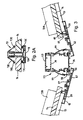
- FIG. 2 shows a vertical section through the main part of the roof.
- the ring beam 10 is formed from an extruded aluminum alloy channel 20 (Figure 4F) having a base wall 21, a long flange 22 projecting from one edge of the base wall and a short flange 23 projecting from the opposed edge of the base wall.
- the base wall 21 is vertical, as illustrated in Figure 2, with the long flange 22 resting on a wall plate laid around the top of the walls of the conservatory.
- the short flange 23 serves to support the lower ends 24 of the glazing bars 13, suitable sealing members 25 being located in grooves formed in the short flange 23, to effect a seal between the glazing bars and ring beam.
- the short flange is curved generally towards the long flange, so as to accommodate glazing bars 13 which may lie at an appropriate angle to the horizontal having regard to the dimensions and configuration of the roof construction.
- the channel 20 has the flanges 22 and 23 directed outwardly of the conservatory and the inwardly directed face of the base wall 21 is trimmed with a pair of valance strips 26, disposed side-by-side.
- These strips 26 ( Figure 4C) are manufactured from extruded plastics or a similar material and have legs 27 permitting those strips to be snap-fitted to corresponding projections 28 provided on the base wall 21 of channel 20.
- Figure 2A is a transverse cross-section through a glazing bar 13, supporting the edges of two sheets 14 of transparent material.
- the glazing bar is assembled from a central aluminium alloy extrusion 13A and a cap 13B pressed on to the central extrusion after laying of the sheets 14. Seals (not shown) are located in grooves 13C and 13D of central section and cap, respectively.
- a valance strip 18 is fitted to the underside of the central section 13A, which valance strip is of the same extrusion as strips 26.
- the ridge member 12 comprises an extruded aluminum alloy central box member 30 ( Figure 4E) and a pair of channels 31 and 32 ( Figure 4F), one to each side of the box member.
- Each of the channels 31 and 32 is of the same extrusion as the extruded channel 20 forming the ring beam 10.
- the projections 28 from the base wall 21 of that extrusion serve to connect each channel to the respective side face of the box member 30, with the two flanges 22 projecting laterally away from the box member, more or less at the bottom of that member, and with the short flanges 23 uppermost.
- the side faces of the box member are provided with suitable grooves to receive the projections 28 of the base wall 21 of the channels, whereby those channels are securely attached to the box member and are prevented from disengaging by means of fixing screws 43 which pass through sections 30 and 31.
- a capping strip 33 ( Figure 4B) is fitted over the ridge beam, which strip rests on the curved short flanges 23 of the two channels 31 and 32, the capping strip being held down by means of bolts (not shown) spaced along the strip and which has their heads located in channel 34 of the capping strip.
- Each bolt projects downwardly through aligned apertures in the upper and lower walls 35 and 36 of the box member, a nut being fitted to the bolt below wall 36.
- Sealing members 37 and 38 are fitted in respective grooves 39 and 40, at the free end of the short flange 23 and in an arm 41 extending away from that short flange.
- a further sealing member (not shown) may be fitted in a groove 42, at the free long edges of the capping strip 33.
- each glazing bar 13 is carried on a support plate 46 ( Figure 4D) pivoted to the upper surface of the lower flange 22 of the respective channels 31 and 32.
- the lower end of each support plate has a re-entrant groove 47 extending therealong, in which is received the head 48 of a projecting bead 49 upstanding from the upper face of the long flange 22.
- the support plate 46 may pivot about a horizontal axis, to accommodate the angle at which the associated glazing bar 13 is to extend.
- Each glazing bar 13 has its own individual support plate, which can slide along the length of the ridge member to the required position.
- each channel is also extruded integrally with each channel, so as to extend generally from the junction between the base wall 21 and the long flange 22, is an arcuate receptor 50 having its curvature centred on the pivotal connection between the support plate 46 and the long flange 22.
- This receptor is provided with spaced teeth 51, the free end 52 of the support plate being engageable with a selected tooth, whereby each support plate may be slid into the ridge member at the appropriate angle for the roof under construction - and typically one of 15, 20, 25 or 30°.
- each glazing bars 13 may be secured to the part of its support plate between its pivotal connection to the long flange 22 and its free end engaged with the receptor by means of a nut and bolt, the head of the bolt being held captive but slidable along channel 54.
- the undersides of the two long flanges 22 and of the lower wall 36 of the box member may be trimmed by three valance strips 53, snap-fitted to the long flanges 22.
- These valance strips 53 are of the same section as the strips 26, ( Figure 4C), fitted to the inwardly directed faces of the ring beam.
- FIG. 3 shows in more detail the valley construction, supporting the lower ends of the glazing bars which intercept that valley.
- the valley member is assembled from a box member 55 (Figure 4E) of the same extrusion as box member 30 of the ridge member, though used the other way up.
- the box member 55 has a pair of ribs 56 one at each of its two lower corners respectively, the outer surface of each rib being of part circular form.
- a glazing bar carrier 57 ( Figure 4A) is pivoted to each of those ribs 56, each such carrier 57 having a re-entrant channel 58 formed along an edge thereof and in which the respective rib 56 is received.
- a glazing bar 13 may be secured to the carrier 57 by means of a screw-threaded fastener (not shown) extending through the free end portion 59 of the carrier.
- a seal (not shown) may be located in groove 60 formed at the upper end of arm 61 upstanding from the carrier.
- each carrier 57 is trimmed by a pair of valance strips 62 arranged side-by-side, each of which strips is of the same configuration as the strips 26 and 53 ( Figure 4C). Moreover, a further valance strip 63, again of the same configuration, is fitted to the top of the box member 55. Seals 64 are located in grooves in the box member 55 and bear against projections upstanding from the carrier 57.
- the roof construction employs six principal extrusions or strips, as shown in Figures 4A to 4F, and several of those are used in different manners. This reduces the initial tooling costs, stocking requirements and numbers of components which have to be transported to a construction site, leading to significant economical advantages as compared to previous known constructions.
Abstract
Description
- This invention relates to a roof construction suitable for use for a conservatory. In particular, this invention relates to various aspects of a conservatory roof construction, as will be explained hereinafter.
- Conservatory roofs may be constructed in a number of different ways. Traditionally, timber members have been cut on site to the required size and were then nailed or screwed together. Glazing was then fitted to glazing bars extending from a ridge beam down to a wall plate, laid around the upper surface of the conservatory walls. Such a roof construction is relatively expensive to implement and so many conservatory roofs are now assembled from pre-formed metal sections, either cut remote from the location at which the roof is to be constructed and then assembled on site, or cut and assembled on site, as appropriate, whereafter multi-wall plastics sheeting is fitted to the glazing bars to complete the roof.
- A typical conservatory roof assembled from metal sections may have a ring beam extending around the upper surface of the conservatory walls, a ridge member disposed approximately centrally between opposed side walls of the conservatory and higher than the ring beam, and glazing bars extending between the ridge member and the ring beam, sloping downwardly from the ridge member to the ring beam. The ridge member typically is of a relatively complex construction in order to have the required strength and also to permit the affixing thereto of glazing bars, at the appropriate angle. For example, such a ridge member may have a number of different components which are typically aluminum extrusions of complex shapes, suitably affixed together. In addition, one or more folded metal strips may be secured to the ridge member, for example to serve as a capping strip and also as valances to conceal fixings, connections and so on.
- The known designs of metal (and usually aluminum alloy) conservatory roof assemblies require the use of a significant number of different extrusions, strips and other sections. For example, it is not uncommon for as many as 60 different sections, strips and so on to be required, ignoring simple fastenings, seals and the like.
- It is accordingly an object of the invention to seek to improve upon known metal conservatory roof constructions, by permitting the use of a relatively small number of different extrusions, sections and other members, whilst still allowing a versatile and flexible arrangement which may be adapted to different installation requirements.
- According to one aspect of the present invention, there is provided a conservatory roof construction comprising a ring beam adapted to be laid around the upper surfaces of the conservatory walls, a ridge member and a plurality of glazing bars extending between the ridge member and the ring beam, the ring beam comprising a channel which defines a surface for supporting the outer ends of the glazing bars, and the ridge member comprising a substantially central member and a pair of channels disposed one to each side of the central member which ridge channels define surfaces for supporting the ridge ends of the glazing bars, the channels of the ridge and of the ring beam being essentially of the same section.
- The design and extrusion of the complex sections used in an aluminium conservatory roof represents a significant part of the overall cost of the roof. With the roof construction of the first aspect of this invention, the same sections are employed for the ring beam and in the fabrication of the ridge member. This allows very significant cost savings, both for initial tooling-up and subsequently, during installation. Moreover, the number of different components which need to be stocked is reduced, as are the number and quantity of materials needed on site when constructing a roof, and this much simplifies the installation.
- In the roof construction of this invention, it is preferred that the ridge and ring beam channels are aluminium alloy extrusions of the same section.
- Preferably, each ridge channel may comprise a base wall, a relatively long flange upstanding from one edge of the base wall, and a relatively short flange upstanding from the opposed other edge of the base wall. In this case, the two ridge channels may be mounted with their base walls extending along respective opposed side faces of the central member, with the long flanges of the channels lowermost, and preferably with those long flanges more or less in the same general plane as the lower face of the central member. Thus, the lower long flanges will project laterally away from the central member, whereby the upper ends of the glazing bars may be fitted to the upwardly directed surfaces of those long flanges.
- The ring beam channel is preferably mounted with the base wall upstanding from the upper surface of the conservatory walls, with the long flange lowermost and the glazing bars resting either directly or indirectly on the upper short flange. To accommodate the range of angles at which glazing bars could extend, in any given construction, the upper short flange of the channel is preferably arcuate, curving downwardly away from the base wall. In this case, the flanges should be directed away from the interior of the conservatory.
- A ridge capping strip may be fitted to the ridge member, both for aesthetic reasons and to impart water-tightness to the construction. Such a ridge capping strip may rest on the short flanges of the two ridge channels, fitted one to each side of the box member. Suitable means should be provided to secure the capping strip in position, such as a plurality of vertically extending bolts held captive in the capping strip at spaced intervals and passing downwardly through an aperture in the central member.
- Valance strips, or trims, may be fitted to the inwardly directed face of the base wall of the channels, where serving as a ring beam and to the under sides of the lower flanges, where serving as a part of the ridge member. By having the width of the long flange substantially equal to the width of the central member, and approximately one half of the width of the base wall of the channel, it is possible to employ a single design of valance strip suitable for overlying the long flange. Then, by fitting such valance strips side-by-side, two such strips may be used effectively to trim the upstanding inwardly-directed face of the base wall of the channel where used as a ring beam, and three such strips may be used effectively to trim the downwardly-directed face of the ridge member, made up of the downwardly-directed lowermost face of the central member together with the downwardly-directed faces of the two long flanges of the two ridge channels respectively, secured to the central member, which is preferably a box member.
- According to a second aspect of this invention, there is provided a conservatory roof construction including a ridge member and a plurality of glazing bars each extending away from and having one end supported by the ridge member, said one end of each glazing bar bearing on a respective support plate pivoted to the ridge member, there being means for selectively setting the relative angle between the plate and the ridge member which means comprises an arcuate receptor centred on the pivot axis of the support plate and having a plurality of spaced engagement means with any one of which the end of the support plate remote from its pivotal connection to the ridge member may be engaged.
- This aspect of the invention provides a particularly simple, easy to use and effective technique for connecting the glazing bars of a conservatory roof to the ridge member, with the bars extending at a selected required angle. In known constructions, the glazing bars are generally arranged to extend at one of a limited number of angles, which in those known constructions the angles are set by clamping the bars using screw-threaded fasteners to the ridge member and ring beam, at the required disposition. Using the technique of the present invention, the teeth of the arcuate receptor define the angles at which the glazing bars, resting on the support plate, may extend in an effective, and rapid to perform, manner.
- The ridge member may have an outwardly projecting flange along each side face and in this case the pivotal connection of the one (upper) end of each glazing bar preferably is arranged at or adjacent the outer end of the flange. Such a pivotal connection may be formed by an inter-engaged headed bead and re-entrant groove provided on the two components pivoted together - and preferably with the bead on the flange and the groove on the underside of the support plate.
- Conveniently, each glazing bar is secured to its support plate by means of a screw-threaded fastener disposed between the pivotal connection of the support plate and the end of the support plate engaged with the receptor.
- This second aspect of the invention is most preferably employed with the first aspect, described above. In this case, the flange advantageously is the long flange of the ridge channel extending along a side face of the ridge box member and the receptor is integrally formed with that ridge channel.
- According to a third aspect of this invention, there is provided a conservatory roof construction comprising a ring beam adapted to be laid around the upper surfaces of the conservatory walls, a ridge member, a plurality of glazing bars extending between the ridge member and the ring beam, and a valley member disposed between two sections of the roof lying in different planes and also extending between the ridge member and the ring beam, the ridge member comprising a central member and a pair of ridge channels disposed one to each side of the member which ridge channels define surfaces for supporting the ridge ends of the glazing bars and the valley member comprising a central member, a pair of carriers mounted one to each side of the member for supporting the lower ends of glazing bars terminating along the valley, the central member of the ridge member being of substantially the same configuration as the member of the valley member.
- It will be appreciated that this third aspect of this invention further reduces the number of different sections required to construct a conservatory roof, using aluminum alloy sections. By connecting the carriers to the same extruded member as is employed for the ridge, a relatively strong valley may be constructed in a simple and effective manner. In a preferred arrangement, one of the central member and the carrier is provided with a integrally-formed headed bead and the other of the central member and the carrier is provided with a re-entrant groove into which the headed bead is fitted, thereby to furnish the pivotal connection therebetween.
- According to yet another aspect of this invention, there is provided a conservatory roof construction comprising a ring beam adapted to be laid around the surfaces of the conservatory walls, a ridge member and a plurality of glazing bars extending between the ridge member and the ring-beam, the inwardly-directed faces of the ring beam and the ridge member being trimmed with elongate valance strips, each valance strip being of the same configuration. Preferably, two such valance strips arranged side-by-side are employed to trim the inwardly directed face (i.e the vertical face) of each ring beam, and three such valance strips arranged side-by-side are used to trim the inwardly directed face (that is, the downwardly-directed face) of the ridge beam.
- In a typical conservatory roof constructed and arranged in accordance with the present invention, any one or more of the aspects of the present invention may be employed. In the specific embodiment of conservatory roof described hereinafter, all four aspects are employed, though it would be possible to use any one, two or three of the aspects, in any particular installation.
- By way of example only, a conservatory roof construction arranged in accordance with the present invention will now be described in detail, with reference being made to the accompanying drawings, in which:-
- Figure 1 diagrammatically illustrates a conservatory having the example of roof of this invention;
- Figure 2 is a vertical section through the roof of Figure 1, with the glazing bars shortened for clarity;
- Figure 2A is a transverse cross-section through a glazing bar shown in Figure 2;
- Figure 3 is a vertical section through a valley member and connected glazing bars; and
- Figures 4A to 4F illustrate the six principal sections used in the roof construction of Figures 2 and 3.
-
- Referring initially to Figure 1, there is shown diagrammatically a conservatory roof construction, assembled from aluminium alloy extrusions and sections which may be cut on site to the appropriate dimensions. This roof includes a
ring beam 10 fitted with a gutter 11, aridge member 12 andglazing bars 13 extending between thering beam 10 and theridge member 12.Sheets 14 of transparent material, such as of triple-wall polycarbonate, are supported by theglazing bars 13. A valley is formed betweenside section 15 of the roof and theadjoining section 16, which valley includes a valley member 17 supporting the lower ends of theglazing bars 13 which adjoin that valley. - Figure 2 shows a vertical section through the main part of the roof. The
ring beam 10 is formed from an extruded aluminum alloy channel 20 (Figure 4F) having abase wall 21, along flange 22 projecting from one edge of the base wall and ashort flange 23 projecting from the opposed edge of the base wall. When used as a ring beam, thebase wall 21 is vertical, as illustrated in Figure 2, with thelong flange 22 resting on a wall plate laid around the top of the walls of the conservatory. Theshort flange 23 serves to support thelower ends 24 of theglazing bars 13, suitable sealingmembers 25 being located in grooves formed in theshort flange 23, to effect a seal between the glazing bars and ring beam. The short flange is curved generally towards the long flange, so as to accommodateglazing bars 13 which may lie at an appropriate angle to the horizontal having regard to the dimensions and configuration of the roof construction. - As shown, the
channel 20 has theflanges base wall 21 is trimmed with a pair ofvalance strips 26, disposed side-by-side. These strips 26 (Figure 4C) are manufactured from extruded plastics or a similar material and havelegs 27 permitting those strips to be snap-fitted tocorresponding projections 28 provided on thebase wall 21 ofchannel 20. - Figure 2A is a transverse cross-section through a
glazing bar 13, supporting the edges of twosheets 14 of transparent material. The glazing bar is assembled from a centralaluminium alloy extrusion 13A and acap 13B pressed on to the central extrusion after laying of thesheets 14. Seals (not shown) are located ingrooves 13C and 13D of central section and cap, respectively. Avalance strip 18 is fitted to the underside of thecentral section 13A, which valance strip is of the same extrusion as strips 26. - The
ridge member 12 comprises an extruded aluminum alloy central box member 30 (Figure 4E) and a pair ofchannels 31 and 32 (Figure 4F), one to each side of the box member. Each of thechannels channel 20 forming thering beam 10. Theprojections 28 from thebase wall 21 of that extrusion serve to connect each channel to the respective side face of the box member 30, with the twoflanges 22 projecting laterally away from the box member, more or less at the bottom of that member, and with theshort flanges 23 uppermost. The side faces of the box member are provided with suitable grooves to receive theprojections 28 of thebase wall 21 of the channels, whereby those channels are securely attached to the box member and are prevented from disengaging by means of fixingscrews 43 which pass throughsections 30 and 31. - A capping strip 33 (Figure 4B) is fitted over the ridge beam, which strip rests on the curved
short flanges 23 of the twochannels channel 34 of the capping strip. Each bolt projects downwardly through aligned apertures in the upper andlower walls wall 36.Sealing members respective grooves short flange 23 and in anarm 41 extending away from that short flange. A further sealing member (not shown) may be fitted in agroove 42, at the free long edges of thecapping strip 33. - The upper end 45 of each
glazing bar 13 is carried on a support plate 46 (Figure 4D) pivoted to the upper surface of thelower flange 22 of therespective channels re-entrant groove 47 extending therealong, in which is received thehead 48 of a projectingbead 49 upstanding from the upper face of thelong flange 22. In this way, thesupport plate 46 may pivot about a horizontal axis, to accommodate the angle at which the associatedglazing bar 13 is to extend. Eachglazing bar 13 has its own individual support plate, which can slide along the length of the ridge member to the required position. - Also extruded integrally with each channel, so as to extend generally from the junction between the
base wall 21 and thelong flange 22, is anarcuate receptor 50 having its curvature centred on the pivotal connection between thesupport plate 46 and thelong flange 22. This receptor is provided with spacedteeth 51, thefree end 52 of the support plate being engageable with a selected tooth, whereby each support plate may be slid into the ridge member at the appropriate angle for the roof under construction - and typically one of 15, 20, 25 or 30°. The upper end 45 of each glazing bars 13 may be secured to the part of its support plate between its pivotal connection to thelong flange 22 and its free end engaged with the receptor by means of a nut and bolt, the head of the bolt being held captive but slidable alongchannel 54. - The undersides of the two
long flanges 22 and of thelower wall 36 of the box member may be trimmed by threevalance strips 53, snap-fitted to thelong flanges 22. These valance strips 53 are of the same section as thestrips 26, (Figure 4C), fitted to the inwardly directed faces of the ring beam. - Figure 3 shows in more detail the valley construction, supporting the lower ends of the glazing bars which intercept that valley. The valley member is assembled from a box member 55 (Figure 4E) of the same extrusion as box member 30 of the ridge member, though used the other way up. As oriented for the valley, the
box member 55 has a pair ofribs 56 one at each of its two lower corners respectively, the outer surface of each rib being of part circular form. A glazing bar carrier 57 (Figure 4A) is pivoted to each of thoseribs 56, eachsuch carrier 57 having are-entrant channel 58 formed along an edge thereof and in which therespective rib 56 is received. The lower end of aglazing bar 13 may be secured to thecarrier 57 by means of a screw-threaded fastener (not shown) extending through thefree end portion 59 of the carrier. A seal (not shown) may be located ingroove 60 formed at the upper end ofarm 61 upstanding from the carrier. - The lower surface of each
carrier 57 is trimmed by a pair of valance strips 62 arranged side-by-side, each of which strips is of the same configuration as thestrips 26 and 53 (Figure 4C). Moreover, afurther valance strip 63, again of the same configuration, is fitted to the top of thebox member 55.Seals 64 are located in grooves in thebox member 55 and bear against projections upstanding from thecarrier 57. - As will be appreciated from the foregoing, the roof construction employs six principal extrusions or strips, as shown in Figures 4A to 4F, and several of those are used in different manners. This reduces the initial tooling costs, stocking requirements and numbers of components which have to be transported to a construction site, leading to significant economical advantages as compared to previous known constructions.
Claims (26)
- A conservatory roof construction comprising a ring beam adapted to be laid around the upper surfaces of the conservatory walls, a ridge member and a plurality of glazing bars extending between the ridge member and the ring beam, the ring beam comprising a channel which defines a surface for supporting the outer ends of the glazing bars, and the ridge member comprising a substantially central member and a pair of channels disposed one to each side of the central member which ridge channels define surfaces for supporting the ridge ends of the glazing bars, the channels of the ridge and of the ring beam being essentially of the same section.
- A conservatory roof construction as claimed in claim 1, wherein the ridge and ring beam channels are aluminium alloy extrusions of the same section.
- A conservatory roof construction as claimed in claim 1 or claim 2, wherein each ridge channel comprises a base wall, a relatively long flange upstanding from one edge of the base wall and a relatively short flange upstanding from the opposed other edge of the base wall.
- A conservatory roof construction as claimed in claim 3, wherein the two ridge channels are mounted with their base walls extending along a respective side face of the central member, with the long flanges of the channels lowermost.
- A conservatory roof construction as claimed in claim 3 or claim 4, wherein the side faces of the central member and the outwardly directed faces of the channel base walls have inter-engaging portions whereby the channels are secured to the central member.
- A conservatory roof construction as claimed in any of claims 3 to 5, wherein the ring beam channel is mounted with its base wall upstanding from the upper surface of the conservatory walls, with the long flange lowermost and with the flanges directed away from the ridge member.
- A conservatory roof construction as claimed in any of claims 3 to 6, wherein the short flange of the ring beam channel has an arcuate profile, curving round towards the long flange away from the base wall of the channel.
- A conservatory roof construction including a ridge member and a plurality of glazing bars each extending away from and having one end supported by the ridge member, said one end of each glazing bar bearing on a respective support plate pivoted to the ridge member, there being means for selectively setting the relative angle between the plate and the ridge member which means comprises an arcuate receptor centred on the pivot axis of the support plate and having a plurality of spaced engagement means with any one of which the end of the support plate remote from its pivotal connection to the ridge member may be engaged.
- A conservatory roof construction as claimed in claim 8, wherein the ridge member has a laterally projecting flange, the pivotal connection between the support plate and the ridge member being arranged at or adjacent the outer end of the flange.
- A conservatory roof construction as claimed in claim 8 or claim 9, wherein the arcuate receptor is formed integrally with a component of the ridge member which defines the outwardly directed flange.
- A conservatory roof construction as claimed in any of claims 8 to 10, wherein one of the ridge member and the support plate is provided with a headed bead and the other of the ridge member and the support plate is provided with a re-entrant groove into which the headed bead is fitted thereby to furnish said pivotal connection.
- A conservatory roof construction as claimed in claim 11, wherein the headed bead upstands from a surface of the ridge member and the re-entrant groove is provided on the underside of the support plate.
- A conservatory roof construction as claimed in any of claims 8 to 12, wherein each glazing bar is secured to its support plate by means of a screw-threaded fastener disposed between the pivotal connection of the support plate and the end of the support plate engaged with said receptor.
- A conservatory roof construction as claimed in any of claims 8 to 13, wherein an individual support plate is provided for each glazing bar, the support plate being slidable along the length of the ridge member to the required position to support its glazing bar.
- A conservatory roof construction as claimed in any of claims 1 to 7, wherein the ridge ends of the glazing bars are connected to the ridge member by an arrangement as claimed in any of claims 8 to 14.
- A conservatory roof construction comprising a ring beam adapted to be laid around the upper surfaces of the conservatory walls, a ridge member, a plurality of glazing bars extending between the ridge member and the ring beam, and a valley member disposed between two sections of the roof lying in different planes and also extending between the ridge member and the ring beam, the ridge member comprising a central member and a pair of ridge channels disposed one to each side of the member which ridge channels define surfaces for supporting the ridge ends of the glazing bars and the valley member comprising a central member, a pair of carriers mounted one to each side of the central member for supporting the lower ends of glazing bars terminating along the valley, the central member of the ridge member being of substantially the same configuration as the central member of the valley member.
- A conservatory roof construction as claimed in claim 16, wherein the central members of the ridge member and the valley member are aluminium alloy extrusions of the same section.
- A conservatory roof construction as claimed in claim 16 or claim 17, wherein each of the carriers is pivotally connected to the central member of the valley member.
- A conservatory roof construction as claimed in claim 18, wherein one of the central member and the carrier is provided with an integrally-formed headed bead and the other of the central member and the carrier is provided with a re-entrant groove into which the headed bead is fitted thereby to furnish said pivotal connection.
- A conservatory roof construction as claimed in claim 18, wherein each of the two headed beads is extruded integrally with the central member of the valley member.
- A conservatory roof construction as claimed in any of claims 16 to 20, wherein each of the carriers extends along the length of the central member of the valley member.
- A conservatory roof construction according to any preceding claim, the or each central member comprising a box member.
- A conservatory roof construction as claimed in any of claims 16 to 22, wherein the ridge ends of the glazing bars are connected to the ridge member by an arrangement as claimed in any of claims 8 to 14.
- A conservatory roof construction as claimed in any of claims 16 to 23, wherein the ring beam and ridge member are arranged as claimed in any of claims 1 to 7.
- A conservatory roof construction comprising a ring beam adapted to be laid around the surfaces of the conservatory walls, a ridge member and a plurality of glazing bars extending between the ridge member and the ring-beam, the inwardly-directed faces of the ring beam and the ridge member being trimmed with elongate valance strips, each strip being of substantially the same configuration.
- A conservatory roof construction as claimed in claim 25, comprising two such valance strips arranged side-by-side to trim an inwardly directed face of each ring beam, and three such valance strips are arranged side-by-side to trim an inwardly directed face of the ridge beam.
Applications Claiming Priority (2)
| Application Number | Priority Date | Filing Date | Title |
|---|---|---|---|
| GBGB9805164.2A GB9805164D0 (en) | 1998-03-12 | 1998-03-12 | Roof construction |
| GB9805164 | 1998-03-12 |
Publications (2)
| Publication Number | Publication Date |
|---|---|
| EP0942110A2 true EP0942110A2 (en) | 1999-09-15 |
| EP0942110A3 EP0942110A3 (en) | 2002-03-20 |
Family
ID=10828359
Family Applications (1)
| Application Number | Title | Priority Date | Filing Date |
|---|---|---|---|
| EP99301841A Withdrawn EP0942110A3 (en) | 1998-03-12 | 1999-03-11 | Roof construction |
Country Status (6)
| Country | Link |
|---|---|
| US (1) | US6223481B1 (en) |
| EP (1) | EP0942110A3 (en) |
| AU (1) | AU758482B2 (en) |
| CA (1) | CA2265285A1 (en) |
| GB (1) | GB9805164D0 (en) |
| NZ (1) | NZ334661A (en) |
Cited By (5)
| Publication number | Priority date | Publication date | Assignee | Title |
|---|---|---|---|---|
| EP1114899A2 (en) * | 2000-01-06 | 2001-07-11 | Richard Anthony Whithing | Components for roof assemblies |
| GB2399104A (en) * | 2003-03-01 | 2004-09-08 | Ultraframe Uk Ltd | A snap-fit roof beam connector |
| US20110258943A1 (en) * | 2010-04-21 | 2011-10-27 | Vic De Zen | Modular building |
| WO2014167361A1 (en) * | 2013-04-12 | 2014-10-16 | Ultraframe (Uk) Limited | Structural beam and kit of connectors therefor |
| GB2521451A (en) * | 2013-12-20 | 2015-06-24 | Ultraframe Uk Ltd | Mounting system |
Families Citing this family (16)
| Publication number | Priority date | Publication date | Assignee | Title |
|---|---|---|---|---|
| DK199900556A (en) * | 1999-04-23 | 2000-10-24 | Velux Ind As | Panel System |
| DK199900555A (en) * | 1999-04-23 | 2000-10-24 | Velux Ind As | Drainage and gasket system as well as a panel system with such a system |
| GB0004521D0 (en) * | 2000-02-26 | 2000-04-19 | Ultraframe Uk Ltd | Roof beams |
| WO2001066871A1 (en) * | 2000-03-08 | 2001-09-13 | Ross Clive Hutton | A device for a valley gutter for a roof |
| US7021014B1 (en) * | 2001-02-20 | 2006-04-04 | Wolfe Michael J | Manufactured building system and method of manufacture and method of transport |
| EP1283311A3 (en) * | 2001-08-01 | 2004-02-11 | Aspect Management Ltd | Conservatory structures |
| EP1396588A1 (en) * | 2002-09-06 | 2004-03-10 | Aspect Management Ltd | Conservatory structures |
| US7392622B2 (en) * | 2002-10-22 | 2008-07-01 | Park Lane Conservatories Limited | Conservatory roof with a soffit system |
| US7246469B2 (en) * | 2002-12-16 | 2007-07-24 | Park Lane Conservatories Ltd. | Multi-piece eaves beam for preassembled glazed roof system |
| US20040163328A1 (en) * | 2003-02-25 | 2004-08-26 | Riley John Michael | Insulated glazed roofing system |
| US7493730B2 (en) * | 2003-10-08 | 2009-02-24 | Fennell Jr Harry C | Method of creating a roof venting space |
| US7392623B2 (en) * | 2004-02-03 | 2008-07-01 | Park Lane Conservatories Ltd. | Eaves beam with framing |
| GB0415331D0 (en) * | 2004-07-08 | 2004-08-11 | Pitman Ronald A | Roofing system for buildings |
| JP6168800B2 (en) * | 2013-03-13 | 2017-07-26 | 株式会社共和 | 庇 |
| US9045905B2 (en) | 2013-03-15 | 2015-06-02 | Bellwether Design Technologies, Llc | Skylight and method of fabricating the same |
| DK180190B1 (en) * | 2018-10-12 | 2020-07-24 | Vkr Holding As | A method for covering a gap between windows at the ridge of a double pitch skylight, a double pitch skylight. |
Citations (11)
| Publication number | Priority date | Publication date | Assignee | Title |
|---|---|---|---|---|
| US3158961A (en) * | 1961-05-19 | 1964-12-01 | Super Sky Products Inc | Adjustable glazing system |
| US4251964A (en) * | 1978-05-16 | 1981-02-24 | Francis Geoffrey V | Glazing system |
| FR2486566A1 (en) * | 1980-07-10 | 1982-01-15 | Aluglas Pvba | Aluminium terrace roof structure - has glass panes supported by hinging profiled intermediate components on main sections |
| FR2525674A1 (en) * | 1982-04-26 | 1983-10-28 | Cathier Daniel | Finishing strip for glazing - has two parallel sections which are vertically offset w.r.t. one another |
| DE3817551C1 (en) * | 1988-05-24 | 1989-09-21 | Wicona-Bausysteme Gmbh & Co Kg, 7900 Ulm, De | |
| DE3809705A1 (en) * | 1988-03-23 | 1989-10-12 | Prokuwa Kunststoff Gmbh | Mounting device |
| GB2252113A (en) * | 1991-01-14 | 1992-07-29 | Norman Ellis | A gutter for a roof of adjustable pitch |
| GB2256880A (en) * | 1991-06-18 | 1992-12-23 | Thermal Profiles Accessories | Conservatories |
| GB2259926A (en) * | 1991-09-27 | 1993-03-31 | Scholes Ernest M H | Roofing component allowing varied roof angles |
| GB2287493A (en) * | 1994-03-16 | 1995-09-20 | Leslie George Briggs | A conservatory roof |
| EP0740026A2 (en) * | 1995-04-29 | 1996-10-30 | Firma J. Eberspächer | Supporting elements for sheets of a glazed roof |
Family Cites Families (6)
| Publication number | Priority date | Publication date | Assignee | Title |
|---|---|---|---|---|
| US3150463A (en) * | 1960-12-19 | 1964-09-29 | J A Nearing Co Inc | Greenhouse |
| US4114330A (en) * | 1976-11-04 | 1978-09-19 | Kawneer Company, Inc. | Skylight system |
| US4261143A (en) * | 1979-07-20 | 1981-04-14 | Michael Rizzo | Pitched roof support structures |
| US5209031A (en) * | 1992-04-10 | 1993-05-11 | John Tavano | Sloped glazing structure |
| US5826380A (en) * | 1996-08-09 | 1998-10-27 | Wolfe; Michael J. | Roof ridge apparatus for adjustable-pitch roof |
| GB9704512D0 (en) * | 1997-03-05 | 1997-04-23 | Ultraframe Plc | Conservatory roofs |
-
1998
- 1998-03-12 GB GBGB9805164.2A patent/GB9805164D0/en not_active Ceased
-
1999
- 1999-03-11 US US09/266,319 patent/US6223481B1/en not_active Expired - Fee Related
- 1999-03-11 EP EP99301841A patent/EP0942110A3/en not_active Withdrawn
- 1999-03-11 CA CA002265285A patent/CA2265285A1/en not_active Abandoned
- 1999-03-11 AU AU20346/99A patent/AU758482B2/en not_active Ceased
- 1999-03-12 NZ NZ334661A patent/NZ334661A/en unknown
Patent Citations (11)
| Publication number | Priority date | Publication date | Assignee | Title |
|---|---|---|---|---|
| US3158961A (en) * | 1961-05-19 | 1964-12-01 | Super Sky Products Inc | Adjustable glazing system |
| US4251964A (en) * | 1978-05-16 | 1981-02-24 | Francis Geoffrey V | Glazing system |
| FR2486566A1 (en) * | 1980-07-10 | 1982-01-15 | Aluglas Pvba | Aluminium terrace roof structure - has glass panes supported by hinging profiled intermediate components on main sections |
| FR2525674A1 (en) * | 1982-04-26 | 1983-10-28 | Cathier Daniel | Finishing strip for glazing - has two parallel sections which are vertically offset w.r.t. one another |
| DE3809705A1 (en) * | 1988-03-23 | 1989-10-12 | Prokuwa Kunststoff Gmbh | Mounting device |
| DE3817551C1 (en) * | 1988-05-24 | 1989-09-21 | Wicona-Bausysteme Gmbh & Co Kg, 7900 Ulm, De | |
| GB2252113A (en) * | 1991-01-14 | 1992-07-29 | Norman Ellis | A gutter for a roof of adjustable pitch |
| GB2256880A (en) * | 1991-06-18 | 1992-12-23 | Thermal Profiles Accessories | Conservatories |
| GB2259926A (en) * | 1991-09-27 | 1993-03-31 | Scholes Ernest M H | Roofing component allowing varied roof angles |
| GB2287493A (en) * | 1994-03-16 | 1995-09-20 | Leslie George Briggs | A conservatory roof |
| EP0740026A2 (en) * | 1995-04-29 | 1996-10-30 | Firma J. Eberspächer | Supporting elements for sheets of a glazed roof |
Cited By (8)
| Publication number | Priority date | Publication date | Assignee | Title |
|---|---|---|---|---|
| EP1114899A2 (en) * | 2000-01-06 | 2001-07-11 | Richard Anthony Whithing | Components for roof assemblies |
| EP1114899A3 (en) * | 2000-01-06 | 2002-01-09 | R A Whiting Design Limited | Components for roof assemblies |
| GB2399104A (en) * | 2003-03-01 | 2004-09-08 | Ultraframe Uk Ltd | A snap-fit roof beam connector |
| GB2399104B (en) * | 2003-03-01 | 2007-01-03 | Ultraframe Uk Ltd | Improvements in and relating to construction of conservatory roofs |
| US20110258943A1 (en) * | 2010-04-21 | 2011-10-27 | Vic De Zen | Modular building |
| WO2014167361A1 (en) * | 2013-04-12 | 2014-10-16 | Ultraframe (Uk) Limited | Structural beam and kit of connectors therefor |
| GB2521451A (en) * | 2013-12-20 | 2015-06-24 | Ultraframe Uk Ltd | Mounting system |
| GB2521451B (en) * | 2013-12-20 | 2020-05-27 | Ultraframe Uk Ltd | Mounting system |
Also Published As
| Publication number | Publication date |
|---|---|
| CA2265285A1 (en) | 1999-09-12 |
| NZ334661A (en) | 2000-10-27 |
| US6223481B1 (en) | 2001-05-01 |
| AU2034699A (en) | 1999-09-23 |
| AU758482B2 (en) | 2003-03-20 |
| GB9805164D0 (en) | 1998-05-06 |
| EP0942110A3 (en) | 2002-03-20 |
Similar Documents
| Publication | Publication Date | Title |
|---|---|---|
| US6223481B1 (en) | Roof construction | |
| US6000176A (en) | Roof ridge assemblies | |
| US4589238A (en) | Skylight sealing | |
| US5671577A (en) | Roofing shingle | |
| GB2256880A (en) | Conservatories | |
| WO2001063069A1 (en) | Roof beams | |
| US4478013A (en) | Sloped glazing structure | |
| EP0473321A1 (en) | Glazing bar | |
| HU224116B1 (en) | Roof cladding element, system and use of the elements | |
| US4389823A (en) | Modular roof skylight | |
| AU757480B2 (en) | Conservatory roof construction | |
| HU206530B (en) | Metal covering plate for covering external wall and roof surfaces | |
| US3932968A (en) | Wall paneling system | |
| US4617773A (en) | Cladding element | |
| EP1254996A2 (en) | Roof ridge assemblies | |
| GB2324815A (en) | Gutter structure for building construction | |
| WO2002097213A1 (en) | Method of assembling a building construction | |
| GB2287048A (en) | Adjustable eaves structure, e.g. for conservatory | |
| US20060048461A1 (en) | Connectors for roofs | |
| EP0115968A2 (en) | Cladding element | |
| JP2561411Y2 (en) | Assembled buildings such as carports | |
| JPH053614Y2 (en) | ||
| AU710112B2 (en) | Ventilated roofing panel support | |
| NL1009783C2 (en) | Edge fixing system for solar panels mounted on tiled roof holds panels parallel to and at fixed distance from roof | |
| GB2138465A (en) | Fastening strips for roof sheeting |
Legal Events
| Date | Code | Title | Description |
|---|---|---|---|
| PUAI | Public reference made under article 153(3) epc to a published international application that has entered the european phase |
Free format text: ORIGINAL CODE: 0009012 |
|
| AK | Designated contracting states |
Kind code of ref document: A2 Designated state(s): AT BE CH CY DE DK ES FI FR GB GR IE IT LI LU MC NL PT SE |
|
| AX | Request for extension of the european patent |
Free format text: AL;LT;LV;MK;RO;SI |
|
| RIN1 | Information on inventor provided before grant (corrected) |
Inventor name: RICKMAN, PAUL DOUGLAS |
|
| PUAL | Search report despatched |
Free format text: ORIGINAL CODE: 0009013 |
|
| AK | Designated contracting states |
Kind code of ref document: A3 Designated state(s): AT BE CH CY DE DK ES FI FR GB GR IE IT LI LU MC NL PT SE |
|
| AX | Request for extension of the european patent |
Free format text: AL;LT;LV;MK;RO;SI |
|
| 17P | Request for examination filed |
Effective date: 20020912 |
|
| AKX | Designation fees paid |
Free format text: AT BE CH CY DE DK ES FI FR GB GR IE IT LI LU MC NL PT SE |
|
| STAA | Information on the status of an ep patent application or granted ep patent |
Free format text: STATUS: THE APPLICATION IS DEEMED TO BE WITHDRAWN |
|
| 18D | Application deemed to be withdrawn |
Effective date: 20041001 |