EP0941707B1 - Method and device for controlling temperature in laser treatment in dentistry - Google Patents
Method and device for controlling temperature in laser treatment in dentistry Download PDFInfo
- Publication number
- EP0941707B1 EP0941707B1 EP99830134A EP99830134A EP0941707B1 EP 0941707 B1 EP0941707 B1 EP 0941707B1 EP 99830134 A EP99830134 A EP 99830134A EP 99830134 A EP99830134 A EP 99830134A EP 0941707 B1 EP0941707 B1 EP 0941707B1
- Authority
- EP
- European Patent Office
- Prior art keywords
- tooth
- type
- laser
- temperature
- treatment
- Prior art date
- Legal status (The legal status is an assumption and is not a legal conclusion. Google has not performed a legal analysis and makes no representation as to the accuracy of the status listed.)
- Expired - Lifetime
Links
Images


Classifications
-
- A—HUMAN NECESSITIES
- A61—MEDICAL OR VETERINARY SCIENCE; HYGIENE
- A61B—DIAGNOSIS; SURGERY; IDENTIFICATION
- A61B18/00—Surgical instruments, devices or methods for transferring non-mechanical forms of energy to or from the body
- A61B18/18—Surgical instruments, devices or methods for transferring non-mechanical forms of energy to or from the body by applying electromagnetic radiation, e.g. microwaves
- A61B18/20—Surgical instruments, devices or methods for transferring non-mechanical forms of energy to or from the body by applying electromagnetic radiation, e.g. microwaves using laser
-
- A—HUMAN NECESSITIES
- A61—MEDICAL OR VETERINARY SCIENCE; HYGIENE
- A61C—DENTISTRY; APPARATUS OR METHODS FOR ORAL OR DENTAL HYGIENE
- A61C1/00—Dental machines for boring or cutting ; General features of dental machines or apparatus, e.g. hand-piece design
- A61C1/0046—Dental lasers
-
- A—HUMAN NECESSITIES
- A61—MEDICAL OR VETERINARY SCIENCE; HYGIENE
- A61B—DIAGNOSIS; SURGERY; IDENTIFICATION
- A61B17/00—Surgical instruments, devices or methods, e.g. tourniquets
- A61B2017/00017—Electrical control of surgical instruments
- A61B2017/00115—Electrical control of surgical instruments with audible or visual output
- A61B2017/00119—Electrical control of surgical instruments with audible or visual output alarm; indicating an abnormal situation
-
- A—HUMAN NECESSITIES
- A61—MEDICAL OR VETERINARY SCIENCE; HYGIENE
- A61B—DIAGNOSIS; SURGERY; IDENTIFICATION
- A61B18/00—Surgical instruments, devices or methods for transferring non-mechanical forms of energy to or from the body
- A61B2018/00636—Sensing and controlling the application of energy
Definitions
- the present invention relates to a device for laser treatment in dentistry and a control method for this treatment, capable of making the use of the device safer and easier when used on hard tissues such as enamel and dentine.
- lasers are also used to treat the hard tissues, namely enamel and dentine.
- a dentist using a laser does not have access to means for directly measuring the temperature of the tooth. This makes the use of lasers in these applications difficult and slow. This is because the dentist is obliged to apply the laser according to his judgment, in other words for sufficiently short periods and with a sufficiently long interval between one application and the next to prevent hazardous rises in the temperature of the tooth.
- Japanese patent no JP 10033548 discloses a device for dental laser treatment where the treatment parameters are set by preliminary irradiating a sample and measuring the temperature of said sample.
- the object of the present invention is to provide a laser device for the treatment of tissues, and in particular a device for orthodontic use, which can be used to overcome the prior art problems described above.
- the object of the present invention is to provide a device which enables the operator to apply the laser without the need to intervene in an empirical and uncertain way with successive interruptions to prevent the risk of overheating of the treated tissues.
- a further object of the present invention is to provide a control method for laser treatment in dentistry which enables overheating of the treated tissue to be prevented.
- Yet another object of the present invention is to provide a method capable of making the use of a laser device for orthodontic applications simpler and safer, particularly in the treatment of hard tissues such as enamel and dentine.
- the alarm situation may be indicated to the operator by means of an acoustic or optical signal or by a combination of the two, or by another suitable method. There is no reason why automatic interruption of the treatment in case of alarm should not be provided.
- the estimated temperature is also determined as a function of the emission power of the laser. It is also possible to provide for the characteristics of the tooth, such as the type of tooth (incisor, canine, molar, premolar), its size and its age, in other words the patient's age, to be considered in the determination of the estimated temperature. The way in which these variables may affect the calculation of the estimated temperature will be described with reference to an example of embodiment.
- the estimated temperature is made to be shown on a graph as a function of the treatment. The operator can thus also determine (in a qualitative way at least) the time available before the limit temperature is reached. This may be useful in some circumstances.
- the device to which the invention is applied consists, in outline (see Fig. 1), of a laser source 1 connected to a treatment set 3, for example by means of an optical fiber 5, an optical path with deflecting mirrors and beam guide tubes, or other.
- the laser source is connected to a programmable central control unit 7, with a keyboard 9 and a monitor 11.
- the laser source 1 is activated by the operator by means of a suitable control, in this example a control pedal 13. Devices of this type are known and do not require further description.
- the central unit 7 is programmable in such a way as to calculate the estimated value of the temperature of the tooth D during the laser treatment, as a function of a set of parameters of the tooth and of the patient undergoing the treatment, and of operating parameters of the device.
- the time constant ⁇ expressed in tenths of a second, is used to determine the estimated variation of the temperature inside the tooth when the tooth is struck by the laser beam for the treatment.
- the equation (1) and the values of the parameters appearing in it, by means of which the time constant ⁇ is calculated, are determined experimentally. They are therefore only provided by way of example, and may be modified to provide more precise values by a longer experimental phase of data acquisition.
- the variation of the temperature inside the tooth depends not only on the characteristics of the tooth, according to which the time constant ⁇ has been determined, but also on the operating conditions, and more particularly on the power of the laser beam, the laser beam emission time, and the initial temperature of the tooth.
- the temperature T max may be considered to depend only on the power W emitted by the laser, the effect of other parameters, such as the tooth size, being disregarded. It has been found by experimental measurement that the temperature T max can be correlated with the power W of the laser, as shown in Table I below: Power (W) (kW) T max (°C) 0 32 1 40 2 42 3 47 4 53 5 58 6 63 7 68 8 72 9 78
- the internal temperature of the tooth is determined by the thermodynamic characteristics of the tooth material, particularly the calorific capacity, and by the balance between the power supplied by the laser and the power dissipated into the environment by the heat dissipation which takes place on the walls of the tooth (in addition to the power removed by the circulation of blood around the tooth and within the tooth, when the tooth is not dead).
- the dissipation of heat into the environment in particular, depends on the size of the tooth. This factor may be disregarded as a first approximation, for the reasons which will be made clear subsequently, but it can be taken into consideration by means of an appropriate trial which can be carried out to find the correlation between the temperature of the tooth, the power of the incident laser beam, and the size of the tooth.
- the operator Before starting the treatment, the operator enters, through the keyboard 9, the data required by the central unit 7 for the determination of the value of the time constant ⁇ . The device then remains in the waiting state until the treatment starts.
- the central unit 7 When the laser emission is started, by activation by means of the pedal 13 after the treatment set 3 has been brought to the point where treatment is required, the central unit 7 reads the parameter "f", in other words the emission frequency, in addition to the parameter "E”, in other words the energy of the laser pulse, and from these it determines the emission power W (Equation 4).
- the central unit 7 calculates the value of T max according to Table I, which is made available to the central unit by a suitable storage system, and enables the plotting of a graph on the monitor 11, which represents the variation with time of the function (3), with the time t on the horizontal axis. Before the plotting of the graph is started, the variable T start is given the actual value (for example the base temperature of the tooth, typically assumed to be 32°C), and the emission time t is reset to zero.
- the time variable t is then gradually incremented in steps, and at each step the central unit 7 determines the estimated value T of the temperature by the equation (3).
- the estimated temperature T is compared with a threshold alarm value T alarm , set, for example, at 40°C. If the value of the estimated temperature T exceeds the value T alarm , the central unit emits an alarm signal, for example an acoustic signal, which indicates to the operator the necessity of suspending the treatment to enable the tooth to cool and to prevent the reaching of temperatures which might damage the pulp tissue.
- the central unit does not emit any alarm. In all cases, it represents the calculated temperature T in graphic form on the monitor 11 and executes the next step of the calculation, after incrementing the time variable (t).
- the power of the laser is 3 W.
- the estimated temperature T is shown on the vertical axis and the time t is shown on the horizontal axis.
- the estimated temperature reaches the alarm value at approximately 26 seconds after the start of the emission. If the emission is not interrupted, the (estimated) internal temperature of the tooth increases up to an asymptotic value of approximately 47°C, which is represented by the parameter T max .
- This asymptotic value varies by approximately +/- 20% if the size of the tooth is also taken into consideration in the calculation of the estimated temperature.
- the profile of the lower region of the curve changes to a negligible extent, and therefore the time taken to reach the alarm temperature is substantially independent of the size of the tooth. For this reason, it was specified initially that the temperature T max (which represents the asymptotic value to which the curve of estimated temperature tends) does not have to allow for the size of the tooth.
- the power W falls to zero and therefore the parameter T max falls to the value of 32°C (base temperature of the tooth).
- equation (3) shows that the temperature T has an exponential variation decreasing asymptotically to the value of 32°C. This variation continues until the next start of the laser emission.
- the central unit 7 then proceeds (with the new values assigned to the parameters T max and T start ) to determine the variation of the temperature with time (decreasing) and to represent this variation on the graph on the monitor 11.
- the movement along the time axis is interrupted for the whole of the time in which the laser emission is equal to zero and the curve representing the estimated temperature T is decreasing. In this way, it is possible to reduce the size of the monitor, or to represent the variation of the temperature T on the monitor for a longer time interval.
- the graph on the monitor therefore shows a straight line parallel to the vertical axis, as shown in Fig. 4, where it is assumed that the laser emission is interrupted at the time t 1 .
- the central unit 7 When the operator considers that the value of the temperature T has fallen sufficiently below the alarm value T alarm , or in any case when the treatment is recommenced, the central unit 7 will again start to detect an exponential increase of the estimated temperature from the value T reached at the instant of starting the second stage of emission.
- the form of the curve representing T will be rising again, since the parameter T start will take the last estimated value of T at the end of the cooling stage in the absence of emission, and the parameter T max will take the value (Table I) corresponding to the emission power, which will now be different from zero.
- the procedure described above is summarized in the general flow chart in Fig. 5 and in the detailed flow charts in Figs. 6 and 7.
- the number 101 indicates the block representing the initialization stage, represented in detail in the diagram in Fig. 2 and described previously.
- the central unit 7 makes cyclic checks to see whether the state of the laser emission controller has been changed, in other words (if the emission has not yet been started) if the laser is still in the non-emitting condition (block 103). If the last monitoring cycle does not find that the laser controller 13 has been activated, the central unit checks whether the plotting of the temperature graph has been enabled (block 106). If the outcome is negative (in other words, if the intervention has not yet been started) the system returns to block 103 and recommences the monitoring cycle.
- the checking process moves to block 107 which checks whether more than one second has elapsed since the preceding check. If the outcome is negative, it returns to block 103; if positive, it proceeds to plot the graph (block 108) to show the estimate of the temperature T for the next step, the graph being plotted in steps of 1 second.
- block 104 If it is found in block 104 that the controller 13 has been activated, this means that the laser has been started or stopped, and that the values of the parameters for the calculation of the estimated temperature T must therefore be changed. If the laser has been started for the first time, the calculation of the function T must be commenced; if the laser has been stopped or restarted after a first stop, the values of the parameters T start and T max must be changed, as described above.
- the parameter E energy of the pulse
- the frequency parameter "f" is read and the emission power W is calculated (blocks 112, 113) and the value T max is determined from the power W (block 114).
- the plotting of the graph on the monitor 11 is then enabled (block 115) and the value of the present temperature (for example 32°C, in other words the base temperature of the tooth) is assigned to the variable T start , while the time variable t is reset to zero (block 116).
- the system then returns to the diagram in Fig. 5, at block 106.
- the central unit finds an interruption of the laser emission instead of a start of the laser emission in block 110, it assigns the last calculated value of the temperature T, in other words the actual temperature, to the variable T start .
- the central unit also assigns the initial value, in other words the value corresponding to a zero emission power, to the variable T max , and resets the time variable t to zero (block 117).
- the control process then returns to the diagram in Fig. 5, at block 106.
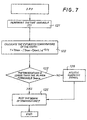
- Fig. 7 shows in detail the procedure for plotting the temperature graph (block 108).
- the time variable (t) is incremented (block 121).
- the temperature T is then estimated (block 122) and the estimated value is compared with the value of T alarm (block 123). If the alarm threshold is not exceeded (T ⁇ T alarm ) the central unit shows the newly calculated value of T on the graph displayed on the monitor 11 (block 125) and returns to block 103 (Fig. 5). If the check at block 123 reveals that the estimated temperature T is equal to or greater than the alarm value (T ⁇ T alarm ), the system emits an alarm (block 126) and then follows the previously described procedure, passing in all cases to block 125 and from there to block 103 in Fig. 5.
Abstract
Description
- The present invention relates to a device for laser treatment in dentistry and a control method for this treatment, capable of making the use of the device safer and easier when used on hard tissues such as enamel and dentine.
- The interaction of lasers with materials, including biological substances, is accompanied to varying degrees by the supply of heat to, and consequently an increase in the temperature of the body struck by the laser energy. In the field of dentistry, lasers are also used to treat the hard tissues, namely enamel and dentine.
- It is known that the living tooth cannot withstand temperature increases in excess of certain known values above the base level without suffering damage to the pulp tissue, with consequent inflammation of this tissue.
- At present, a dentist using a laser does not have access to means for directly measuring the temperature of the tooth. This makes the use of lasers in these applications difficult and slow. This is because the dentist is obliged to apply the laser according to his judgment, in other words for sufficiently short periods and with a sufficiently long interval between one application and the next to prevent hazardous rises in the temperature of the tooth.
- Japanese patent no JP 10033548 discloses a device for dental laser treatment where the treatment parameters are set by preliminary irradiating a sample and measuring the temperature of said sample.
- The object of the present invention is to provide a laser device for the treatment of tissues, and in particular a device for orthodontic use, which can be used to overcome the prior art problems described above.
- More particularly, the object of the present invention is to provide a device which enables the operator to apply the laser without the need to intervene in an empirical and uncertain way with successive interruptions to prevent the risk of overheating of the treated tissues.
- A further object of the present invention is to provide a control method for laser treatment in dentistry which enables overheating of the treated tissue to be prevented.
- Yet another object of the present invention is to provide a method capable of making the use of a laser device for orthodontic applications simpler and safer, particularly in the treatment of hard tissues such as enamel and dentine.
- These and other objects and advantages, which will be apparent from the following text to a person skilled in the art, are essentially achieved with a method for controlling the internal temperature of a tooth subjected to a laser beam treatment during said treatment, in which an estimated internal temperature of the tooth is determined as a function of at least one operating parameter of the laser and of the treatment time, and in which the estimated temperature is compared with a threshold temperature, the exceeding of said threshold temperature causing an alarm condition.
- The alarm situation may be indicated to the operator by means of an acoustic or optical signal or by a combination of the two, or by another suitable method. There is no reason why automatic interruption of the treatment in case of alarm should not be provided.
- By implementing this method in the laser treatment device, it is possible to provide the operator with a reliable and sufficiently precise estimate of the variation of temperature inside the tooth. The operator will be informed by the device when this temperature exceeds a threshold value, and will no longer be obliged to operate in an empirical and random way. This makes the device safer and much simpler to use, since all the risk situations due to the distraction of the operator will be eliminated. The estimate of the internal temperature of the tooth, which increases as a result of the supply of energy by the laser, is produced in an objective way on the basis of parameters set at the start of the treatment, and consequently the treatment is interrupted if, and only if, this is actually necessary.
- It is also possible to provide for the emission of an enabling signal (or end of alarm signal) when, following an interruption of the power supply, the estimated temperature has fallen sufficiently below the alarm limit value. Alternatively, or in combination with the foregoing, it is possible to provide for the laser source to be automatically cut off for the time required to make the temperature fall below a certain value with respect to the limit value.
- In a particular embodiment of the method according to the present invention, the estimated temperature is also determined as a function of the emission power of the laser. It is also possible to provide for the characteristics of the tooth, such as the type of tooth (incisor, canine, molar, premolar), its size and its age, in other words the patient's age, to be considered in the determination of the estimated temperature. The way in which these variables may affect the calculation of the estimated temperature will be described with reference to an example of embodiment.
- In a particularly simple embodiment of the invention, it is possible to simply provide for the emission of an alarm signal and/or the interruption of the emission of the laser beam. However, in order to provide the operator with more information, and also to make the operation simpler and safer, in a preferred embodiment of the invention the estimated temperature is made to be shown on a graph as a function of the treatment. The operator can thus also determine (in a qualitative way at least) the time available before the limit temperature is reached. This may be useful in some circumstances.
- Further advantageous embodiments and details of the execution of the method according to the invention, and of a device according to the invention, are described below and indicated in the attached claims.
- The invention will be more clearly understood from the description and the attached drawing, which shows a practical and non-restrictive example of the invention. In the drawing,
- Fig. 1 is a diagram of a device to which the present invention may be applied;
- Fig. 2 is a block diagram of the data initialization stage;
- Fig. 3 is a graph showing an example of the variation of the estimated temperature;
- Fig. 4 is another graph showing an example of the variation of the estimated temperature;
- Fig. 5 is a block diagram summarizing the method; and
- Figs. 6 and 7 are two detailed block diagrams of two stages of the method summarized in the diagram in Fig. 5.
-
- The device to which the invention is applied consists, in outline (see Fig. 1), of a
laser source 1 connected to a treatment set 3, for example by means of anoptical fiber 5, an optical path with deflecting mirrors and beam guide tubes, or other. The laser source is connected to a programmable central control unit 7, with a keyboard 9 and amonitor 11. Thelaser source 1 is activated by the operator by means of a suitable control, in this example acontrol pedal 13. Devices of this type are known and do not require further description. - According to the invention, the central unit 7 is programmable in such a way as to calculate the estimated value of the temperature of the tooth D during the laser treatment, as a function of a set of parameters of the tooth and of the patient undergoing the treatment, and of operating parameters of the device.
- The parameters relating to the subject and to the tooth to be treated are: the type of tooth, the size of the tooth and the age of the patient. More particularly, the size of the tooth is defined by a parameter Ksize, which can take the values Ksize = 3, 5 and 7 for small, medium and large teeth respectively, while the type of tooth is defined by a parameter Ktooth_type which takes the following values:
- incisor:
- Ktooth_type = 92
- canine:
- Ktooth_type = 90
- premolar:
- Ktooth_type = 91
- molar:
- Ktooth_type = 120
- Before starting the treatment, in an initialization phase the operator enters the data specified above by means of the keyboard 9, and on the basis of these data the central unit 7 determines a time constant τ by the following function:
- The time constant τ, expressed in tenths of a second, is used to determine the estimated variation of the temperature inside the tooth when the tooth is struck by the laser beam for the treatment. The equation (1) and the values of the parameters appearing in it, by means of which the time constant τ is calculated, are determined experimentally. They are therefore only provided by way of example, and may be modified to provide more precise values by a longer experimental phase of data acquisition.
- The invention is not, therefore, restricted in any way to these numerical values, which are provided solely by way of example, although they may be considered to have been optimized in the light of present experimental results. It should also be borne in mind that the experimental results on which these values are based were obtained from dead biological material, and were therefore considerably influenced by the quality of the material, particularly its freshness.
- The procedure of initializing the variables described above is summarized schematically in the block diagram in Fig. 2.
- The variation of the temperature inside the tooth depends not only on the characteristics of the tooth, according to which the time constant τ has been determined, but also on the operating conditions, and more particularly on the power of the laser beam, the laser beam emission time, and the initial temperature of the tooth. The variation of the estimated internal temperature of the tooth follows an exponential path which can be approximated with the function:
- T
- is the estimated temperature;
- Tmax
- is a parameter dependent on the power of the laser beam and possibly also on the characteristics of the tooth, particularly its size. It represents the asymptotic value to which the internal temperature of the tooth tends for a given value of the incident power;
- Tstart
- is the initial temperature;
- t
- is the time; and
- τ
- is the time constant defined above (see Equation 1).
- To determine the value of the temperature Tmax, the power W emitted by the laser is initially calculated as the energy E of the laser pulse and the frequency f of repetition of the pulses:
- As a first approximation, the temperature Tmax may be considered to depend only on the power W emitted by the laser, the effect of other parameters, such as the tooth size, being disregarded. It has been found by experimental measurement that the temperature Tmax can be correlated with the power W of the laser, as shown in Table I below:
Power (W) (kW) Tmax (°C) 0 32 1 40 2 42 3 47 4 53 5 58 6 63 7 68 8 72 9 78 - In reality, the internal temperature of the tooth is determined by the thermodynamic characteristics of the tooth material, particularly the calorific capacity, and by the balance between the power supplied by the laser and the power dissipated into the environment by the heat dissipation which takes place on the walls of the tooth (in addition to the power removed by the circulation of blood around the tooth and within the tooth, when the tooth is not dead). The dissipation of heat into the environment, in particular, depends on the size of the tooth. This factor may be disregarded as a first approximation, for the reasons which will be made clear subsequently, but it can be taken into consideration by means of an appropriate trial which can be carried out to find the correlation between the temperature of the tooth, the power of the incident laser beam, and the size of the tooth.
- Before starting the treatment, the operator enters, through the keyboard 9, the data required by the central unit 7 for the determination of the value of the time constant τ. The device then remains in the waiting state until the treatment starts.
- When the laser emission is started, by activation by means of the pedal 13 after the treatment set 3 has been brought to the point where treatment is required, the central unit 7 reads the parameter "f", in other words the emission frequency, in addition to the parameter "E", in other words the energy of the laser pulse, and from these it determines the emission power W (Equation 4). The central unit 7 calculates the value of Tmax according to Table I, which is made available to the central unit by a suitable storage system, and enables the plotting of a graph on the
monitor 11, which represents the variation with time of the function (3), with the time t on the horizontal axis. Before the plotting of the graph is started, the variable Tstart is given the actual value (for example the base temperature of the tooth, typically assumed to be 32°C), and the emission time t is reset to zero. - The time variable t is then gradually incremented in steps, and at each step the central unit 7 determines the estimated value T of the temperature by the equation (3). In each cycle of the iteration, the estimated temperature T is compared with a threshold alarm value Talarm, set, for example, at 40°C. If the value of the estimated temperature T exceeds the value Talarm, the central unit emits an alarm signal, for example an acoustic signal, which indicates to the operator the necessity of suspending the treatment to enable the tooth to cool and to prevent the reaching of temperatures which might damage the pulp tissue.
- If the estimated value of T at a given step does not exceed the value Talarm, the central unit does not emit any alarm. In all cases, it represents the calculated temperature T in graphic form on the
monitor 11 and executes the next step of the calculation, after incrementing the time variable (t). - Fig. 3 shows the curve representing the temperature T estimated by this procedure for a small molar (parameters Ksize = 7; Ktooth_type = 120). The power of the laser is 3 W. The estimated temperature T is shown on the vertical axis and the time t is shown on the horizontal axis.
- It is easy to see that the estimated temperature reaches the alarm value at approximately 26 seconds after the start of the emission. If the emission is not interrupted, the (estimated) internal temperature of the tooth increases up to an asymptotic value of approximately 47°C, which is represented by the parameter Tmax. This asymptotic value varies by approximately +/- 20% if the size of the tooth is also taken into consideration in the calculation of the estimated temperature. However, even when this further parameter is taken into consideration, the profile of the lower region of the curve changes to a negligible extent, and therefore the time taken to reach the alarm temperature is substantially independent of the size of the tooth. For this reason, it was specified initially that the temperature Tmax (which represents the asymptotic value to which the curve of estimated temperature tends) does not have to allow for the size of the tooth.
- When, as a result of the emission of an alarm signal, or for any other reason, the operator interrupts the laser emission by releasing the
pedal 13, the power W falls to zero and therefore the parameter Tmax falls to the value of 32°C (base temperature of the tooth). The tooth is at a temperature equal to the last value estimated for the temperature T. This value is then taken by the central unit as the value of Tstart, while the parameter Tmax takes the value of 32°C (see Table I for W=0). - Given these two values of the parameters Tmax and Tstart, equation (3) shows that the temperature T has an exponential variation decreasing asymptotically to the value of 32°C. This variation continues until the next start of the laser emission.
- The central unit 7 then proceeds (with the new values assigned to the parameters Tmax and Tstart) to determine the variation of the temperature with time (decreasing) and to represent this variation on the graph on the
monitor 11. For reasons of practicality, the movement along the time axis is interrupted for the whole of the time in which the laser emission is equal to zero and the curve representing the estimated temperature T is decreasing. In this way, it is possible to reduce the size of the monitor, or to represent the variation of the temperature T on the monitor for a longer time interval. When the laser is not emitting, the graph on the monitor therefore shows a straight line parallel to the vertical axis, as shown in Fig. 4, where it is assumed that the laser emission is interrupted at the time t1. - When the operator considers that the value of the temperature T has fallen sufficiently below the alarm value Talarm, or in any case when the treatment is recommenced, the central unit 7 will again start to detect an exponential increase of the estimated temperature from the value T reached at the instant of starting the second stage of emission. The form of the curve representing T will be rising again, since the parameter Tstart will take the last estimated value of T at the end of the cooling stage in the absence of emission, and the parameter Tmax will take the value (Table I) corresponding to the emission power, which will now be different from zero.
- The procedure described above is summarized in the general flow chart in Fig. 5 and in the detailed flow charts in Figs. 6 and 7. In the diagram in Fig. 5, the
number 101 indicates the block representing the initialization stage, represented in detail in the diagram in Fig. 2 and described previously. On completion of the initialization stage, the central unit 7 makes cyclic checks to see whether the state of the laser emission controller has been changed, in other words (if the emission has not yet been started) if the laser is still in the non-emitting condition (block 103). If the last monitoring cycle does not find that thelaser controller 13 has been activated, the central unit checks whether the plotting of the temperature graph has been enabled (block 106). If the outcome is negative (in other words, if the intervention has not yet been started) the system returns to block 103 and recommences the monitoring cycle. - If the system has already been activated, the checking process moves to block 107 which checks whether more than one second has elapsed since the preceding check. If the outcome is negative, it returns to block 103; if positive, it proceeds to plot the graph (block 108) to show the estimate of the temperature T for the next step, the graph being plotted in steps of 1 second.
- If it is found in
block 104 that thecontroller 13 has been activated, this means that the laser has been started or stopped, and that the values of the parameters for the calculation of the estimated temperature T must therefore be changed. If the laser has been started for the first time, the calculation of the function T must be commenced; if the laser has been stopped or restarted after a first stop, the values of the parameters Tstart and Tmax must be changed, as described above. For this purpose, the central unit executes block 105, which is shown in detail in the diagram in Fig. 6. An initial check is made to see whether the laser has been activated (start of laser emission = yes) or if it has been stopped (start of laser emission = no). In the first case, the parameter E (energy of the pulse) is read byblock 111, and then the frequency parameter "f" is read and the emission power W is calculated (blocks 112, 113) and the value Tmax is determined from the power W (block 114). The plotting of the graph on themonitor 11 is then enabled (block 115) and the value of the present temperature (for example 32°C, in other words the base temperature of the tooth) is assigned to the variable Tstart, while the time variable t is reset to zero (block 116). The system then returns to the diagram in Fig. 5, atblock 106. - If the central unit finds an interruption of the laser emission instead of a start of the laser emission in
block 110, it assigns the last calculated value of the temperature T, in other words the actual temperature, to the variable Tstart. The central unit also assigns the initial value, in other words the value corresponding to a zero emission power, to the variable Tmax, and resets the time variable t to zero (block 117). The control process then returns to the diagram in Fig. 5, atblock 106. - Fig. 7 shows in detail the procedure for plotting the temperature graph (block 108). The time variable (t) is incremented (block 121). The temperature T is then estimated (block 122) and the estimated value is compared with the value of Talarm (block 123). If the alarm threshold is not exceeded (T<Talarm) the central unit shows the newly calculated value of T on the graph displayed on the monitor 11 (block 125) and returns to block 103 (Fig. 5). If the check at
block 123 reveals that the estimated temperature T is equal to or greater than the alarm value (T≥Talarm), the system emits an alarm (block 126) and then follows the previously described procedure, passing in all cases to block 125 and from there to block 103 in Fig. 5. - It is to be understood that the drawing shows only an example provided solely as a practical demonstration of the invention, and that this invention may vary in its forms and arrangements without departure from the scope of the guiding concept of the invention. The presence of any reference numbers in the attached claims has the purpose of facilitating the reading of the claims with reference to the description and to the drawing, and does not limit the scope of protection represented by the claims.
Claims (28)
- A method for controlling the internal temperature of a tooth (D) subjected to a treatment by a laser beam during said treatment, wherein an estimated internal temperature (T) of the tooth is determined as a function of, at least, an operating parameter of the laser and the treatment time (t), and wherein the estimated temperature (T) is compared with a threshold temperature (Talarm), the exceeding of said threshold temperature generating an alarm condition.
- The method as claimed in claim 1, wherein said alarm condition comprises the emission of an acoustic signal and/or an optical signal.
- The method as claimed in claim 1 or 2, wherein said estimated temperature is determined as a function of the emission power (W) of the laser.
- The method as claimed in claim 1 or 2 or 3, wherein said estimated temperature is determined additionally as a function of the characteristics of the tooth subjected to the laser treatment.
- The method as claimed in claim 4, wherein said characteristics of the tooth comprise one or more of the following parameters: size, type of tooth, age.
- The method as claimed in one or more of the preceding claims, wherein said estimated temperature is determined according to the following equation:
- t
- is the treatment time;
- Tstart
- is the initial temperature of the tooth;
- Tmax
- is a parameter dependent at least on the emission power of the laser;
- τ
- is a time constant which is a function of the characteristics of the tooth.
- The method as claimed in claim 6, wherein Tmax is a parameter dependent on the emission power of the laser and the size of the tooth.
- The method as claimed in claim 6 or 7, wherein the time constant is determined according to the equation
- Kage
- is a constant determined by the age;
- Ksize
- is a constant determined by the size of the tooth;
- Ktooth_type
- is a constant determined by the type of tooth.
- The method as claimed in claim 8, wherein Kage is defined by
- The method as claimed in claim 8 or 9, wherein Ksize varies from 2 to 10 and preferably from 3 to 7, and increases with the size of the tooth.
- The method as claimed in claim 8 or 9 or 10, wherein Ktooth_type varies from 70 to 150 and preferably from 90 to 120, as a function of the type of tooth.
- The method as claimed in claim 11, wherein Ktooth_type takes the following values as a function of the type of tooth:
- incisor:
- Ktooth_type = 92
- canine:
- Ktooth_type = 90
- premolar:
- Ktooth_type = 91
- molar:
- Ktooth_type = 120
- The method as claimed in one or more of the preceding claims, wherein the estimated temperature is shown on a graph as a function of the treatment time.
- The method as claimed in claim 13, wherein during the stages of interruption of the laser emission, in which the estimated temperature decreases, the variation of the estimated temperature is shown on the graph as moving along the vertical axis but without movement along the horizontal axis.
- A device for dental treatment by means of a laser beam, including a laser source (1), a treatment set (3) for treating a tooth (D), a central control unit (7) connected to said laser source and to means (13) of turning the laser beam on and off, characterized in that said central unit is programmed to apply a method as claimed in one or more of claims 1 to 14.
- A device for dental treatment by means of a laser beam, including a laser source (1), a treatment set (3) for treating a tooth (D), a central control unit (7) connected to said laser source and to means (13) of turning the laser beam on and off, characterized in that said central unit comprises means for determining an estimated internal temperature (T) of the tooth subjected to the treatment by means of a beam emitted by said laser source as a function of, at least, an operating parameter of the laser and the treatment time (t), said central unit comparing said estimated temperature (T) with a threshold temperature (Talarm), the exceeding of said threshold temperature causing the generation of an alarm signal.
- The device as claimed in claim 16, wherein said central unit determines the estimated temperature as a function of the emission power (W) of said laser source (1).
- The device as claimed in claim 16 or 17, characterized in that said central unit (7) is programmed to determine said estimated temperature (T) additionally as a function of the characteristics of the tooth subjected to the laser treatment.
- The device as claimed in one or more of claims 16 to 18, characterized in that said central unit is programmed to determine said estimated temperature (T) as a function of one or more of the following parameters: size of the tooth, type of tooth, age.
- The device as claimed in one or more of claims 16 to 19, characterized in that said central unit is programmed to determine said estimated temperature according to the following equation:
- t
- is the treatment time;
- Tstart
- is the initial temperature of the tooth;
- Tmax
- is a parameter dependent at least on the emission power of the laser;
- τ
- is a time constant which is a function of the characteristics of the tooth.
- The device as claimed in claim 20, characterized in that Tmax is a parameter dependent on the emission power of the laser source and on the size of the tooth.
- The device as claimed in claim 20 or 21, characterized in that the central unit determines the time constant τ according to the equation
- Kage
- is a constant determined by the age;
- Ksize
- is a constant determined by the size of the tooth;
- Ktooth_type
- is a constant determined by the type of tooth.
- The device as claimed in claim 22, characterized in that Kage is defined by
- The device as claimed in claim 22 or 23, in which Ksize varies from 2 to 10 and preferably from 3 to 7, and increases with the size of the tooth.
- The device as claimed in claim 22 or 23 or 24, characterized in that Ktooth_type varies from 70 to 150 and preferably from 90 to 120, as a function of the type of tooth.
- The device as claimed in claim 25, in which Ktooth_type takes the following values as a function of the type of tooth:
- incisor:
- Ktooth_type = 92
- canine:
- Ktooth_type = 90
- premolar:
- Ktooth_type = 91
- molar:
- Ktooth_type = 120
- The device as claimed in one or more of claims 16 to 26, characterized in that it comprises a display means (11) on which is displayed a graph showing the variation of the estimated temperature as a function of the treatment time.
- The device as claimed in claim 27, characterized in that said central unit (7) is programmed in such a way that during the stages of interruption of the laser emission, in which the estimated temperature decreases, the variation of the estimated temperature is shown on the graph as moving along the vertical axis but without movement along the horizontal axis.
Applications Claiming Priority (2)
| Application Number | Priority Date | Filing Date | Title |
|---|---|---|---|
| IT98FI000059A ITFI980059A1 (en) | 1998-03-13 | 1998-03-13 | METHOD AND DEVICE FOR TEMPERATURE CONTROL IN LASER TREATMENT IN DENTISTRY |
| ITFI980059 | 1998-03-13 |
Publications (3)
| Publication Number | Publication Date |
|---|---|
| EP0941707A2 EP0941707A2 (en) | 1999-09-15 |
| EP0941707A3 EP0941707A3 (en) | 2002-07-31 |
| EP0941707B1 true EP0941707B1 (en) | 2005-05-04 |
Family
ID=11352440
Family Applications (1)
| Application Number | Title | Priority Date | Filing Date |
|---|---|---|---|
| EP99830134A Expired - Lifetime EP0941707B1 (en) | 1998-03-13 | 1999-03-12 | Method and device for controlling temperature in laser treatment in dentistry |
Country Status (4)
| Country | Link |
|---|---|
| EP (1) | EP0941707B1 (en) |
| AT (1) | ATE294541T1 (en) |
| DE (1) | DE69925060T2 (en) |
| IT (1) | ITFI980059A1 (en) |
Cited By (1)
| Publication number | Priority date | Publication date | Assignee | Title |
|---|---|---|---|---|
| WO2019161410A1 (en) * | 2018-02-19 | 2019-08-22 | Millennium Healthcare Technologies, Inc. | Dental lasing device system and method |
Families Citing this family (1)
| Publication number | Priority date | Publication date | Assignee | Title |
|---|---|---|---|---|
| AT500141B1 (en) | 2004-04-28 | 2008-03-15 | W & H Dentalwerk Buermoos Gmbh | DENTAL LASER TREATMENT DEVICE |
Family Cites Families (3)
| Publication number | Priority date | Publication date | Assignee | Title |
|---|---|---|---|---|
| US5735846A (en) * | 1994-06-27 | 1998-04-07 | Ep Technologies, Inc. | Systems and methods for ablating body tissue using predicted maximum tissue temperature |
| US5662643A (en) * | 1994-09-28 | 1997-09-02 | Abiomed R & D, Inc. | Laser welding system |
| JPH1033548A (en) * | 1996-07-29 | 1998-02-10 | Matsushita Electric Ind Co Ltd | Laser operating device |
-
1998
- 1998-03-13 IT IT98FI000059A patent/ITFI980059A1/en unknown
-
1999
- 1999-03-12 DE DE69925060T patent/DE69925060T2/en not_active Expired - Lifetime
- 1999-03-12 EP EP99830134A patent/EP0941707B1/en not_active Expired - Lifetime
- 1999-03-12 AT AT99830134T patent/ATE294541T1/en not_active IP Right Cessation
Cited By (1)
| Publication number | Priority date | Publication date | Assignee | Title |
|---|---|---|---|---|
| WO2019161410A1 (en) * | 2018-02-19 | 2019-08-22 | Millennium Healthcare Technologies, Inc. | Dental lasing device system and method |
Also Published As
| Publication number | Publication date |
|---|---|
| ATE294541T1 (en) | 2005-05-15 |
| EP0941707A3 (en) | 2002-07-31 |
| ITFI980059A0 (en) | 1998-03-13 |
| DE69925060T2 (en) | 2005-09-22 |
| ITFI980059A1 (en) | 1999-09-13 |
| EP0941707A2 (en) | 1999-09-15 |
| DE69925060D1 (en) | 2005-06-09 |
Similar Documents
| Publication | Publication Date | Title |
|---|---|---|
| CA2816967C (en) | Initiation sequences for ramping-up pulse power in a medical laser having high-intensity leading subpulses | |
| JP2723119B2 (en) | Dental treatment equipment | |
| US20210069756A1 (en) | Laser system and method for operating the laser system | |
| RU2711426C1 (en) | Method for sealing of root canal | |
| EP0830851B1 (en) | Fiber-optic endodontic apparatus | |
| US20100167226A1 (en) | System and method for dental applications without optical connectors in console, and handpiece assembly therefor | |
| Sarp et al. | Ceramic bracket debonding with ytterbium fiber laser | |
| US5330517A (en) | Device for treating tissue by pulse sequence group | |
| AU708100B2 (en) | Pulsed light source for removing biological tissue | |
| US7869016B2 (en) | Fiber damage detection and protection device | |
| JPH11502130A (en) | Apparatus used for laser treatment of living tissue | |
| EP0374262A1 (en) | Laser-aided intracoeliac operation equipment | |
| CN102355874A (en) | Method and device for non-invasive temperature determination in biological tissue treated with treatment radiation | |
| EP0941707B1 (en) | Method and device for controlling temperature in laser treatment in dentistry | |
| Bodrumlu et al. | Temperature variation during apicectomy with Er: YAG laser | |
| Cecchini et al. | Evaluation of two laser systems for intracanal irradiation | |
| JP2005204905A (en) | Electronic endoscope apparatus with light irradiation control function | |
| Pfefer et al. | Dynamics of pulsed holmium: YAG laser photocoagulation of albumen | |
| CA1327062C (en) | Laser operating device for intracavitary surgery | |
| CN113545843B (en) | Laser ablation system and method | |
| JP2005192889A (en) | Method and apparatus for monitoring thermal injury in laser dental care | |
| KR101705591B1 (en) | Laser irradiation device for medical | |
| Meire et al. | Principle and antimicrobial efficacy of laser‐activated irrigation: A narrative review | |
| KR20230119270A (en) | System for preventative dental hard tissue treatment with a laser | |
| Dostalova et al. | Laser radiation propagation in the hard and soft dental tissues |
Legal Events
| Date | Code | Title | Description |
|---|---|---|---|
| PUAI | Public reference made under article 153(3) epc to a published international application that has entered the european phase |
Free format text: ORIGINAL CODE: 0009012 |
|
| AK | Designated contracting states |
Kind code of ref document: A2 Designated state(s): AT BE CH CY DE DK ES FI FR GB GR IE IT LI LU MC NL PT SE |
|
| AX | Request for extension of the european patent |
Free format text: AL;LT;LV;MK;RO;SI |
|
| PUAL | Search report despatched |
Free format text: ORIGINAL CODE: 0009013 |
|
| RIC1 | Information provided on ipc code assigned before grant |
Free format text: 7A 61C 1/00 A, 7A 61B 18/20 B |
|
| AK | Designated contracting states |
Kind code of ref document: A3 Designated state(s): AT BE CH CY DE DK ES FI FR GB GR IE IT LI LU MC NL PT SE |
|
| AX | Request for extension of the european patent |
Free format text: AL;LT;LV;MK;RO;SI |
|
| 17P | Request for examination filed |
Effective date: 20021127 |
|
| AKX | Designation fees paid |
Designated state(s): AT BE CH DE DK ES FI FR GB GR IE IT LI LU MC NL PT SE |
|
| GRAP | Despatch of communication of intention to grant a patent |
Free format text: ORIGINAL CODE: EPIDOSNIGR1 |
|
| GRAS | Grant fee paid |
Free format text: ORIGINAL CODE: EPIDOSNIGR3 |
|
| GRAA | (expected) grant |
Free format text: ORIGINAL CODE: 0009210 |
|
| AK | Designated contracting states |
Kind code of ref document: B1 Designated state(s): AT BE CH DE DK ES FI FR GB GR IE IT LI LU MC NL PT SE |
|
| PG25 | Lapsed in a contracting state [announced via postgrant information from national office to epo] |
Ref country code: NL Free format text: LAPSE BECAUSE OF FAILURE TO SUBMIT A TRANSLATION OF THE DESCRIPTION OR TO PAY THE FEE WITHIN THE PRESCRIBED TIME-LIMIT Effective date: 20050504 Ref country code: LI Free format text: LAPSE BECAUSE OF FAILURE TO SUBMIT A TRANSLATION OF THE DESCRIPTION OR TO PAY THE FEE WITHIN THE PRESCRIBED TIME-LIMIT Effective date: 20050504 Ref country code: IT Free format text: LAPSE BECAUSE OF FAILURE TO SUBMIT A TRANSLATION OF THE DESCRIPTION OR TO PAY THE FEE WITHIN THE PRESCRIBED TIME-LIMIT;WARNING: LAPSES OF ITALIAN PATENTS WITH EFFECTIVE DATE BEFORE 2007 MAY HAVE OCCURRED AT ANY TIME BEFORE 2007. THE CORRECT EFFECTIVE DATE MAY BE DIFFERENT FROM THE ONE RECORDED. Effective date: 20050504 Ref country code: FI Free format text: LAPSE BECAUSE OF FAILURE TO SUBMIT A TRANSLATION OF THE DESCRIPTION OR TO PAY THE FEE WITHIN THE PRESCRIBED TIME-LIMIT Effective date: 20050504 Ref country code: CH Free format text: LAPSE BECAUSE OF FAILURE TO SUBMIT A TRANSLATION OF THE DESCRIPTION OR TO PAY THE FEE WITHIN THE PRESCRIBED TIME-LIMIT Effective date: 20050504 Ref country code: BE Free format text: LAPSE BECAUSE OF FAILURE TO SUBMIT A TRANSLATION OF THE DESCRIPTION OR TO PAY THE FEE WITHIN THE PRESCRIBED TIME-LIMIT Effective date: 20050504 Ref country code: AT Free format text: LAPSE BECAUSE OF FAILURE TO SUBMIT A TRANSLATION OF THE DESCRIPTION OR TO PAY THE FEE WITHIN THE PRESCRIBED TIME-LIMIT Effective date: 20050504 |
|
| REG | Reference to a national code |
Ref country code: GB Ref legal event code: FG4D |
|
| REG | Reference to a national code |
Ref country code: CH Ref legal event code: EP |
|
| REG | Reference to a national code |
Ref country code: IE Ref legal event code: FG4D |
|
| REF | Corresponds to: |
Ref document number: 69925060 Country of ref document: DE Date of ref document: 20050609 Kind code of ref document: P |
|
| PG25 | Lapsed in a contracting state [announced via postgrant information from national office to epo] |
Ref country code: SE Free format text: LAPSE BECAUSE OF FAILURE TO SUBMIT A TRANSLATION OF THE DESCRIPTION OR TO PAY THE FEE WITHIN THE PRESCRIBED TIME-LIMIT Effective date: 20050804 Ref country code: GR Free format text: LAPSE BECAUSE OF FAILURE TO SUBMIT A TRANSLATION OF THE DESCRIPTION OR TO PAY THE FEE WITHIN THE PRESCRIBED TIME-LIMIT Effective date: 20050804 Ref country code: DK Free format text: LAPSE BECAUSE OF FAILURE TO SUBMIT A TRANSLATION OF THE DESCRIPTION OR TO PAY THE FEE WITHIN THE PRESCRIBED TIME-LIMIT Effective date: 20050804 |
|
| PG25 | Lapsed in a contracting state [announced via postgrant information from national office to epo] |
Ref country code: PT Free format text: LAPSE BECAUSE OF FAILURE TO SUBMIT A TRANSLATION OF THE DESCRIPTION OR TO PAY THE FEE WITHIN THE PRESCRIBED TIME-LIMIT Effective date: 20051017 |
|
| NLV1 | Nl: lapsed or annulled due to failure to fulfill the requirements of art. 29p and 29m of the patents act | ||
| REG | Reference to a national code |
Ref country code: CH Ref legal event code: PL |
|
| PLBE | No opposition filed within time limit |
Free format text: ORIGINAL CODE: 0009261 |
|
| STAA | Information on the status of an ep patent application or granted ep patent |
Free format text: STATUS: NO OPPOSITION FILED WITHIN TIME LIMIT |
|
| PG25 | Lapsed in a contracting state [announced via postgrant information from national office to epo] |
Ref country code: GB Free format text: LAPSE BECAUSE OF NON-PAYMENT OF DUE FEES Effective date: 20060312 |
|
| PG25 | Lapsed in a contracting state [announced via postgrant information from national office to epo] |
Ref country code: IE Free format text: LAPSE BECAUSE OF NON-PAYMENT OF DUE FEES Effective date: 20060313 |
|
| ET | Fr: translation filed | ||
| PG25 | Lapsed in a contracting state [announced via postgrant information from national office to epo] |
Ref country code: MC Free format text: LAPSE BECAUSE OF NON-PAYMENT OF DUE FEES Effective date: 20060331 Ref country code: LU Free format text: LAPSE BECAUSE OF NON-PAYMENT OF DUE FEES Effective date: 20060331 |
|
| 26N | No opposition filed |
Effective date: 20060207 |
|
| GBPC | Gb: european patent ceased through non-payment of renewal fee |
Effective date: 20060312 |
|
| REG | Reference to a national code |
Ref country code: IE Ref legal event code: MM4A |
|
| PG25 | Lapsed in a contracting state [announced via postgrant information from national office to epo] |
Ref country code: ES Free format text: LAPSE BECAUSE OF NON-PAYMENT OF DUE FEES Effective date: 20060331 |
|
| PGFP | Annual fee paid to national office [announced via postgrant information from national office to epo] |
Ref country code: FR Payment date: 20140227 Year of fee payment: 16 |
|
| PGFP | Annual fee paid to national office [announced via postgrant information from national office to epo] |
Ref country code: DE Payment date: 20140415 Year of fee payment: 16 |
|
| REG | Reference to a national code |
Ref country code: DE Ref legal event code: R119 Ref document number: 69925060 Country of ref document: DE |
|
| REG | Reference to a national code |
Ref country code: FR Ref legal event code: ST Effective date: 20151130 |
|
| PG25 | Lapsed in a contracting state [announced via postgrant information from national office to epo] |
Ref country code: DE Free format text: LAPSE BECAUSE OF NON-PAYMENT OF DUE FEES Effective date: 20151001 |
|
| PG25 | Lapsed in a contracting state [announced via postgrant information from national office to epo] |
Ref country code: FR Free format text: LAPSE BECAUSE OF NON-PAYMENT OF DUE FEES Effective date: 20150331 |