EP0941659B1 - Device for treating waters in a basin - Google Patents
Device for treating waters in a basin Download PDFInfo
- Publication number
- EP0941659B1 EP0941659B1 EP99830095A EP99830095A EP0941659B1 EP 0941659 B1 EP0941659 B1 EP 0941659B1 EP 99830095 A EP99830095 A EP 99830095A EP 99830095 A EP99830095 A EP 99830095A EP 0941659 B1 EP0941659 B1 EP 0941659B1
- Authority
- EP
- European Patent Office
- Prior art keywords
- shaft
- operating group
- base structure
- decompression chamber
- propeller
- Prior art date
- Legal status (The legal status is an assumption and is not a legal conclusion. Google has not performed a legal analysis and makes no representation as to the accuracy of the status listed.)
- Expired - Lifetime
Links
- 239000003643 water by type Substances 0.000 title claims description 4
- XLYOFNOQVPJJNP-UHFFFAOYSA-N water Substances O XLYOFNOQVPJJNP-UHFFFAOYSA-N 0.000 claims description 34
- 230000006837 decompression Effects 0.000 claims description 26
- 230000000284 resting effect Effects 0.000 claims description 13
- 238000007789 sealing Methods 0.000 claims description 13
- 239000004033 plastic Substances 0.000 claims description 6
- 239000007787 solid Substances 0.000 claims description 5
- 238000005096 rolling process Methods 0.000 claims description 4
- 239000004677 Nylon Substances 0.000 claims description 2
- 239000012530 fluid Substances 0.000 claims description 2
- 230000001050 lubricating effect Effects 0.000 claims description 2
- 229920001778 nylon Polymers 0.000 claims description 2
- 239000000463 material Substances 0.000 description 5
- 239000013536 elastomeric material Substances 0.000 description 3
- OKTJSMMVPCPJKN-UHFFFAOYSA-N Carbon Chemical compound [C] OKTJSMMVPCPJKN-UHFFFAOYSA-N 0.000 description 2
- 238000005273 aeration Methods 0.000 description 2
- QVGXLLKOCUKJST-UHFFFAOYSA-N atomic oxygen Chemical compound [O] QVGXLLKOCUKJST-UHFFFAOYSA-N 0.000 description 2
- 229910010293 ceramic material Inorganic materials 0.000 description 2
- 238000007872 degassing Methods 0.000 description 2
- 229910002804 graphite Inorganic materials 0.000 description 2
- 239000010439 graphite Substances 0.000 description 2
- 229910052760 oxygen Inorganic materials 0.000 description 2
- 239000001301 oxygen Substances 0.000 description 2
- 239000004809 Teflon Substances 0.000 description 1
- 229920006362 Teflon® Polymers 0.000 description 1
- 238000009360 aquaculture Methods 0.000 description 1
- 230000015556 catabolic process Effects 0.000 description 1
- 230000007797 corrosion Effects 0.000 description 1
- 238000005260 corrosion Methods 0.000 description 1
- 230000008595 infiltration Effects 0.000 description 1
- 238000001764 infiltration Methods 0.000 description 1
- 238000012423 maintenance Methods 0.000 description 1
- 230000007257 malfunction Effects 0.000 description 1
- 230000001706 oxygenating effect Effects 0.000 description 1
- 238000009372 pisciculture Methods 0.000 description 1
- 238000000746 purification Methods 0.000 description 1
- 238000003756 stirring Methods 0.000 description 1
- 239000000126 substance Substances 0.000 description 1
Images
Classifications
-
- B—PERFORMING OPERATIONS; TRANSPORTING
- B01—PHYSICAL OR CHEMICAL PROCESSES OR APPARATUS IN GENERAL
- B01F—MIXING, e.g. DISSOLVING, EMULSIFYING OR DISPERSING
- B01F27/00—Mixers with rotary stirring devices in fixed receptacles; Kneaders
- B01F27/25—Mixers with both stirrer and drive unit submerged in the material being mixed
-
- A—HUMAN NECESSITIES
- A01—AGRICULTURE; FORESTRY; ANIMAL HUSBANDRY; HUNTING; TRAPPING; FISHING
- A01K—ANIMAL HUSBANDRY; AVICULTURE; APICULTURE; PISCICULTURE; FISHING; REARING OR BREEDING ANIMALS, NOT OTHERWISE PROVIDED FOR; NEW BREEDS OF ANIMALS
- A01K63/00—Receptacles for live fish, e.g. aquaria; Terraria
- A01K63/04—Arrangements for treating water specially adapted to receptacles for live fish
- A01K63/042—Introducing gases into the water, e.g. aerators, air pumps
-
- Y—GENERAL TAGGING OF NEW TECHNOLOGICAL DEVELOPMENTS; GENERAL TAGGING OF CROSS-SECTIONAL TECHNOLOGIES SPANNING OVER SEVERAL SECTIONS OF THE IPC; TECHNICAL SUBJECTS COVERED BY FORMER USPC CROSS-REFERENCE ART COLLECTIONS [XRACs] AND DIGESTS
- Y10—TECHNICAL SUBJECTS COVERED BY FORMER USPC
- Y10S—TECHNICAL SUBJECTS COVERED BY FORMER USPC CROSS-REFERENCE ART COLLECTIONS [XRACs] AND DIGESTS
- Y10S261/00—Gas and liquid contact apparatus
- Y10S261/71—Sewage aerators; rotating
Definitions
- the present invention relates to a device for treating waters in a basin.
- the invention is advantageously used in different types of basins, such as, for example, tanks for aquiculture, fish-farming basins, aeration tanks of water purification plants, lakes undergoing reclamation, etc.
- the device in question may be used in particular for aerating and/or oxygenating the waters, but it may also serve for other types of water treatment, such as, for example, stirring, degassing, destratification, de-icing, remixing, etc.
- the present invention refers to a device provided with an operating group immersed in the water and comprising a decompression chamber, a rotating propeller and a motor for driving the propeller.
- the decompression chamber has an inlet communicating with a suction duct which emerges above the free surface of the water, and an outlet immersed in the water; the propeller is situated outside the decompression chamber in the vicinity of the outlet.
- operation of the propeller empties the decompression chamber of the water and causes, via the suction duct, sucking-in of air which is mixed with the water in the basin.
- a device of this type is already known from the European publication EP 0,562,314 which illustrates a floating structure made of plastic material and comprising two parallel, hollow, floating cables underneath which the operating group is located. This device has, however, certain drawbacks.
- the operating group may touch the bottom, with the consequent incorrect operation or breakdown of the device.
- FR-A-1 248 837 and US-A-4 259 257 show attaching supporting legs or points to a water treating devices in order to solve the problem of preventing the operating group from touching the bottom of the basin.
- the object of the present invention is that of providing a device which is able to overcome the abovementioned drawbacks.
- One advantage of the invention in question is that of providing a device which is particularly stable both inside and outside the water.
- Another advantage is that, even when the device is outside the water, the operating group is protected against accidental knocks.
- a further advantage is that of eliminating the risk that, in the event of a considerable drop in the level of the water inside the basin, the operating group may touch the bottom of the basin itself.
- Yet another advantage is that, in a device constructed in accordance with the invention, it is possible to adjust easily, and over a wide range, the arrangement of the axis of rotation of the propeller; in particular, the device may selectively operate with the axis of the propeller horizontal, vertical or inclined at different angles.
- a final advantage consists in the fact that the device is able to operate also without the aid of a floating structure, when it is simply rested on the bottom of the basin.
- 1 denotes in its entirety a device, constructed in accordance with the present invention, for treating a mass of water contained in a basin.
- the device 1 comprises a floating structure 2 comprising two hollow, parallel and spaced floats 3 which are made of a plastic material and joined together by a horizontal flat element 4. The latter is made of plastic material and formed as one piece with the floats 3.
- the floating structure 2 has two sliding guides 5 with a vertical sliding axis. Each guide 5 is integral with a respective float 3. Two respective pipes 6 with a vertical axis are slidably coupled with the sliding guides 5. At the top, each pipe 6 terminates in an inlet mouth which is covered by a dome-shaped protection piece 7 which is open at the bottom.
- Each protection piece 7 prevents the entry, from above, of objects into the inlet mouth and at the same time allows the entry of air into the respective pipe 6 via the mouth itself, passing through an annular opening defined between the pipe and the associated protection piece, as indicated by the arrows F.
- Locking means which are known and not shown, are provided for selectively fixing in position the pipes 6 with respect to the sliding guides 5.
- the floating structure 2 comprises, immersed in the water, an operating group indicated in its entirety by 8.
- the operating group 8 comprises at least: a decompression chamber 9, a rotating propeller 10 and a motor (known and not shown) for driving the propeller.
- the device 1 also comprises a base structure 12 which is immersed in the water and to which the operating group 8 is attached. The bottom ends of the pipes 6 are rigidly engaged with the base structure 12.
- Said structure 12 may be made of plastic material, for example the same material from which the floats are made.
- the base structure 12 consists in the case in question in two lateral support elements 13 which are arranged alongside each other and substantially extend in a vertical plane and are specularly symmetrical.
- Each support element 13 is internally hollow, are parallel and spaced from one another and are joined together by one or more horizontal cross-pieces 14.
- Each support element 13 has in a central zone a weight-reducing opening 15, so that overall the shape of each element 13 is substantially annular.
- the operating group 8 is arranged in the space between the two support elements 13.
- This base structure 12 is provided with at least three bottom resting points which are located underneath the operating group 8 and by means of which the device 1 may be rested on top of an external solid surface.
- Each support element 13 is provided at the base with two support feet 17, the bottom surface of which is relatively wide and has at least one of the abovementioned resting points 16. Therefore, in the case in question, the base structure 12 has four support feet 17 with which at least one possible bottom resting point 16 is associated.
- the base structure 12 is provided with at least three lateral resting points 18 which are situated alongside the operating group 8 and by means of which the structure 12 may be laid with one side on top of an external solid surface, as illustrated in Figure 7.
- the abovementioned lateral resting points 18 are situated on the opposite side to the propeller 10.
- the operating group 8 has at least two ends 20, 21 which are joined to the base structure 12.
- a first end 20 is rotatably coupled to the base structure 12, with the axis of rotation x-x preferably horizontal, and a second end 21 can be positioned on the base structure.
- the second end 21 is removably fixed to one of the cross-pieces 14 which join the two support elements 13.
- the position of this cross-piece 14 and the second end 21 of the operating group associated with it is adjustable: for this purpose, the opposite ends of this cross-piece 14 may be fixed to the support elements 13 in a plurality of different positions: in fact, a plurality of fastening points 22 are positioned on an arc of a circle, with which points the ends of the cross-piece 14 may be engaged. These fastening points 22 are present on both the support elements 13 and are arranged circumferentially around the axis of rotation x-x of the operating group 8.
- the operating group 8 comprises a cylindrical part 23 which is sealingly closed with respect to the exterior and contains the motor - known and not shown - which can be of the electric or fluid-operated type.
- the decompression chamber is defined by the walls of a casing 24. This chamber 9 has at least one inlet 25 and at least one outlet 26. In the case in question the chamber 9 has two opposite side inlets 25.
- Each side inlet 25 communicates with a suction duct 28 comprising a channel 29 formed inside a respective support element 13.
- Each channel 29 has an end communicating with the decompression chamber 9 and an opposite end communicating with one of the two vertical pipes 6 which emerge above the free surface of the water.
- the bottom end of each pipe 6 is attached to a respective support element 13 and has a mouth communicating with the channel 29 inside said element. Therefore the suction ducts 28 are formed, at least partly, inside the base structure 12.
- 11 indicates a water-tight container which is intended to contain electrical power supply terminals of the electric cable 30 which penetrates inside the casing 24 of the motor by means of the sealed connector 27.
- the outlet 26 of the decompression chamber is immersed in the water.
- the rotating propeller 10 is situated completely outside the decompression chamber 9 in the vicinity of the outlet 26.
- the side inlets 25 of the decompression chamber are situated in the vicinity of the axis x-x about which the operating group 8 is able to rotate.
- the propeller 10 is connected to the motor by means of a shaft 31 which passes through the decompression chamber 9.
- One end 32 of the shaft 31 is integrally joined, by means of keying, to a hub 33 which carries the propeller 10 and which is situated opposite the outlet 26 of the decompression chamber.
- This end 32 of the shaft has a sealed-closing cap 34 which is housed inside a cavity of the hub 33 and is designed to prevent infiltration of water into the space between the joining surfaces of the shaft 31 and the hub 33.
- the latter has, inside it, channels 35 with their axis parallel to the axis of rotation of the propeller 10 and arranged circumferentially about said axis. These channels 35 connect the decompression chamber 9 to an air outlet opening 36 which is formed centrally inside the hub 33.
- the shaft 31 has a first section 37 which is surrounded by an annular chamber 38 sealingly closed and delimited by walls of the casing 24.
- the annular chamber 38 is intended to contain a lubricating fluid (oil).
- the shaft 31 also has a second section 39 which acts as a pivot for rotation and which has, coupled to it, a rolling support 40 consisting for example of a conventional ball-bearing system.
- the first section 37 of the shaft is located between the end 32 with the hub 33 and the second section 39 with the rolling support 40.
- the first section 37 has, mounted on it, first sealing means 41 which are designed to close off sealingly the annular chamber 38 full of oil both from the decompression chamber 9 and from the rolling support 40.
- the decompression chamber 9 has, arranged inside it, second sealing means 42 which are designed to close off further in a sealing manner the connection between the annular chamber 38 and the decompression chamber 9.
- the first sealing means 41 comprise: a first annular gasket 43 which is made of elastomeric material, is fixed and has an L-shaped cross-section and is seated so as to make contact with the shoulder of the casing 24; a first ring 44 which is made of ceramic material, is fixed and seated in the cavity of the first annular gasket 43; a first annular sealing member 45 which is made of graphite, is rotationally integral with the shaft 31 and is intended during to use to form a sliding-contact seal against the first ring 44.
- the first sealing means 41 also comprise a group of elements which is composed of a second annular gasket 46, a second ring 47 and a second annular sealing member 48 which are identical and symmetrical with respect to the similar elements 43, 44, 45 indicated previously.
- a resilient member 49 (spring) and a sleeve 50 made of elastomeric material are arranged between the two groups of elements.
- the resilient member 49 ensures the sliding contact between the rings 44, 47 made of ceramic material and the annular sealing members 45, 48 made of graphite.
- the resilient sleeve 50 surrounds coaxially a section of the shaft 31.
- the second sealing means 42 comprise an annular element 52 which is preferably made of rigid plastic (Teflon) and which lines a part of the shaft 31 and is rotationally integral with the latter.
- One end 53 of the annular element 52 is gripped with contact between the hub 33 and the shaft 31, while the opposite end has an annular lip 54 which makes sealing contact against a fixed surface of the casing 24.
- a middle part 55 of the annular element 52 surrounds, with contact, an end part of the tubular lining sheath 51.
- the cap 34 and the annular element 52 co-operate so as to protect the shaft 31 from contact with the water contained in the basin: it is possible to provide, as an addition or as an alternative, other means which are able to insulate, from the water, the end of the shaft which carries the propeller 10 and which passes through the decompression chamber 9: it has been found that the use of insulating means reduces considerably corrosion phenomena affecting the shaft itself.
- the motor causes rotation of the propeller 10, resulting in the water which initially fills the decompression chamber 9 being sucked out.
- the latter is emptied of the water.
- a drop in pressure occurs inside the chamber 9, with the consequent suction of air (and/or oxygen and/other substances) from outside through the various suction ducts 6, 29, 30.
- the sucked air, to which oxygen is added if necessary, is then sucked up through the channels 35 in the hub 35 and then mixed with the mass of water contained in the basin.
- Figure 7 shows a particular operational configuration of the device, in which the operating group 8 is arranged with the axis of rotation of the propeller 10 vertical: in this case the base structure 12 is rotated through 90° with respect to the configuration in Figure 3 and is connected to the vertical suction pipes 6 by means of 90° elbow connectors which can be removably fitted if required.
- the base structure 12 In the case where the water level in the basin drops considerably, the base structure 12 is able to rest, with its bottom support feet 17, on the bottom of the basin, so that the operating group 8 never manages to touch the bottom itself, thus eliminating the risk of damage or malfunctions. It is also possible to use the device 1 without the need for a top floating structure 2: in this case the base structure 12 is rested on the bottom of the basin and the operating group 8 is able to operate, since it is nevertheless located at a distance from the bottom itself.
- the motor is preferably mounted on supports made of elastomeric material, mainly with the aim of reducing the vibrations when the device, during operation, is not floating on the water, but is resting on a solid surface.
- the bottom support is provided by the resting points 18 which are situated laterally on the opposite side to the propeller 10.
- Figures 4 and 5 show, purely by way of example, two different possible orientations of the operating group 8 in a vertical plane.
- the adjustment of the depth and the orientation of the operating group allow the device to be used to perform various functions such as, for example, aeration, degassing, circulation, destratification and de-icing.
- the operating group 8 can be supported with a considerable degree of stability.
- the base structure 12 also provides protection for the operating group 8 when the device is not in the water; in this connection it must be pointed out that the operating group 8 is enclosed within the dimensions of the base structure 12 both in the vertical and in the horizontal direction.
- the operating group 8 is also able to function without the aid of the floats, when said structure is simply rested on the bottom, as for example shown in Fig. 7.
- the suction ducts 28 may simply emerge slightly above the free surface of the water, without being attached to any floating structure.
Landscapes
- Life Sciences & Earth Sciences (AREA)
- Environmental Sciences (AREA)
- Chemical Kinetics & Catalysis (AREA)
- Biodiversity & Conservation Biology (AREA)
- Animal Husbandry (AREA)
- Chemical & Material Sciences (AREA)
- Marine Sciences & Fisheries (AREA)
- Farming Of Fish And Shellfish (AREA)
- Aeration Devices For Treatment Of Activated Polluted Sludge (AREA)
- Gasification And Melting Of Waste (AREA)
- Paper (AREA)
- Sink And Installation For Waste Water (AREA)
- Sewage (AREA)
- Other Liquid Machine Or Engine Such As Wave Power Use (AREA)
Description
- The present invention relates to a device for treating waters in a basin.
- More specifically, but not exclusively, the invention is advantageously used in different types of basins, such as, for example, tanks for aquiculture, fish-farming basins, aeration tanks of water purification plants, lakes undergoing reclamation, etc. The device in question may be used in particular for aerating and/or oxygenating the waters, but it may also serve for other types of water treatment, such as, for example, stirring, degassing, destratification, de-icing, remixing, etc.
- Various types of apparatus which perform the abovementioned tasks are already known; some of these are illustrated, for example, in the following patent publications: DE 3,417,039, EP 0,088,850, US 4,157,304, US 4,409,107, US 4,514,343, US 4,732,682, US 4,741,825, US 4,882,099, US 4,954,295 and US 5,118,450.
- In particular the present invention refers to a device provided with an operating group immersed in the water and comprising a decompression chamber, a rotating propeller and a motor for driving the propeller. The decompression chamber has an inlet communicating with a suction duct which emerges above the free surface of the water, and an outlet immersed in the water; the propeller is situated outside the decompression chamber in the vicinity of the outlet. During use, operation of the propeller empties the decompression chamber of the water and causes, via the suction duct, sucking-in of air which is mixed with the water in the basin.
- A device of this type is already known from the European publication EP 0,562,314 which illustrates a floating structure made of plastic material and comprising two parallel, hollow, floating cables underneath which the operating group is located. This device has, however, certain drawbacks.
- Firstly, in the case where the level of the water inside the basin falls, the operating group may touch the bottom, with the consequent incorrect operation or breakdown of the device.
- Secondly, when the device is outside the water - for example so that operations such as storage, transportation, checking, maintenance, etc., may be performed - the motor is exposed to accidental knocks with the risk of damage.
- FR-A-1 248 837 and US-A-4 259 257 show attaching supporting legs or points to a water treating devices in order to solve the problem of preventing the operating group from touching the bottom of the basin.
- The object of the present invention is that of providing a device which is able to overcome the abovementioned drawbacks.
- One advantage of the invention in question is that of providing a device which is particularly stable both inside and outside the water.
- Another advantage is that, even when the device is outside the water, the operating group is protected against accidental knocks.
- A further advantage is that of eliminating the risk that, in the event of a considerable drop in the level of the water inside the basin, the operating group may touch the bottom of the basin itself.
- Yet another advantage is that, in a device constructed in accordance with the invention, it is possible to adjust easily, and over a wide range, the arrangement of the axis of rotation of the propeller; in particular, the device may selectively operate with the axis of the propeller horizontal, vertical or inclined at different angles.
- A final advantage consists in the fact that the device is able to operate also without the aid of a floating structure, when it is simply rested on the bottom of the basin.
- These objects and advantages are achieved by the invention in question, as is characterized by the claims indicated below.
- The invention is described below in detail with reference to the accompanying figures, which illustrate a preferred embodiment thereof.
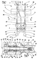
- Figure 1 shows a schematic, partial, vertical elevation view of an example of embodiment of the device in question;
- Figure 2 shows, on a larger scale, a cross-section along the horizontal plane indicated by II-II in Figure 1;
- Figure 3 shows, on a smaller scale, a cross-section along the plane indicated by III-III in Figure 2;
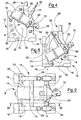
- Figures 4 and 5 show two different operating configurations of the device, with the operating group differently oriented;
- Figure 6 shows a detail of Figure 3, on a larger scale and cross-sectioned;
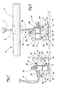
- Figure 7 shows the device according to Figure 3, slightly modified and in a different operating condition (tipped over), and resting on the bottom of the basin.
-
- With reference to the abovementioned Figures, 1 denotes in its entirety a device, constructed in accordance with the present invention, for treating a mass of water contained in a basin.
- The
device 1 comprises afloating structure 2 comprising two hollow, parallel and spaced floats 3 which are made of a plastic material and joined together by a horizontalflat element 4. The latter is made of plastic material and formed as one piece with the floats 3. Thefloating structure 2 has two sliding guides 5 with a vertical sliding axis. Each guide 5 is integral with a respective float 3. Two respective pipes 6 with a vertical axis are slidably coupled with the sliding guides 5. At the top, each pipe 6 terminates in an inlet mouth which is covered by a dome-shaped protection piece 7 which is open at the bottom. Eachprotection piece 7 prevents the entry, from above, of objects into the inlet mouth and at the same time allows the entry of air into the respective pipe 6 via the mouth itself, passing through an annular opening defined between the pipe and the associated protection piece, as indicated by the arrows F. Locking means, which are known and not shown, are provided for selectively fixing in position the pipes 6 with respect to the sliding guides 5. - The
floating structure 2 comprises, immersed in the water, an operating group indicated in its entirety by 8. Theoperating group 8 comprises at least: adecompression chamber 9, arotating propeller 10 and a motor (known and not shown) for driving the propeller. Thedevice 1 also comprises abase structure 12 which is immersed in the water and to which theoperating group 8 is attached. The bottom ends of the pipes 6 are rigidly engaged with thebase structure 12. - Said
structure 12 may be made of plastic material, for example the same material from which the floats are made. Thebase structure 12 consists in the case in question in twolateral support elements 13 which are arranged alongside each other and substantially extend in a vertical plane and are specularly symmetrical. - These
elements 13 are internally hollow, are parallel and spaced from one another and are joined together by one or morehorizontal cross-pieces 14. Eachsupport element 13 has in a central zone a weight-reducingopening 15, so that overall the shape of eachelement 13 is substantially annular. Theoperating group 8 is arranged in the space between the twosupport elements 13. - This
base structure 12 is provided with at least three bottom resting points which are located underneath theoperating group 8 and by means of which thedevice 1 may be rested on top of an external solid surface. Eachsupport element 13 is provided at the base with twosupport feet 17, the bottom surface of which is relatively wide and has at least one of theabovementioned resting points 16. Therefore, in the case in question, thebase structure 12 has foursupport feet 17 with which at least one possiblebottom resting point 16 is associated. - Externally, the
base structure 12 is provided with at least threelateral resting points 18 which are situated alongside theoperating group 8 and by means of which thestructure 12 may be laid with one side on top of an external solid surface, as illustrated in Figure 7. In this particular case, there are at least fourlateral resting points 18, two of which are arranged on the side surface of twobottom support feet 17; another twolateral resting points 18 are arranged on another twofurther support feet 19 which are located laterally on the top zone of the twosupport elements 13. The abovementionedlateral resting points 18 are situated on the opposite side to thepropeller 10. - The
operating group 8 has at least twoends base structure 12. In the particular case, afirst end 20 is rotatably coupled to thebase structure 12, with the axis of rotation x-x preferably horizontal, and asecond end 21 can be positioned on the base structure. In particular thesecond end 21 is removably fixed to one of thecross-pieces 14 which join the twosupport elements 13. The position of thiscross-piece 14 and thesecond end 21 of the operating group associated with it is adjustable: for this purpose, the opposite ends of thiscross-piece 14 may be fixed to thesupport elements 13 in a plurality of different positions: in fact, a plurality offastening points 22 are positioned on an arc of a circle, with which points the ends of thecross-piece 14 may be engaged. Thesefastening points 22 are present on both thesupport elements 13 and are arranged circumferentially around the axis of rotation x-x of theoperating group 8. - The
operating group 8 comprises acylindrical part 23 which is sealingly closed with respect to the exterior and contains the motor - known and not shown - which can be of the electric or fluid-operated type. The decompression chamber is defined by the walls of acasing 24. Thischamber 9 has at least oneinlet 25 and at least oneoutlet 26. In the case in question thechamber 9 has twoopposite side inlets 25. - Each side inlet 25 communicates with a
suction duct 28 comprising achannel 29 formed inside arespective support element 13. Eachchannel 29 has an end communicating with thedecompression chamber 9 and an opposite end communicating with one of the two vertical pipes 6 which emerge above the free surface of the water. The bottom end of each pipe 6 is attached to arespective support element 13 and has a mouth communicating with thechannel 29 inside said element. Therefore thesuction ducts 28 are formed, at least partly, inside thebase structure 12. - 11 indicates a water-tight container which is intended to contain electrical power supply terminals of the
electric cable 30 which penetrates inside thecasing 24 of the motor by means of the sealedconnector 27. - The
outlet 26 of the decompression chamber is immersed in the water. The rotatingpropeller 10 is situated completely outside thedecompression chamber 9 in the vicinity of theoutlet 26. The side inlets 25 of the decompression chamber are situated in the vicinity of the axis x-x about which theoperating group 8 is able to rotate. Thepropeller 10 is connected to the motor by means of ashaft 31 which passes through thedecompression chamber 9. - One
end 32 of theshaft 31 is integrally joined, by means of keying, to ahub 33 which carries thepropeller 10 and which is situated opposite theoutlet 26 of the decompression chamber. Thisend 32 of the shaft has a sealed-closing cap 34 which is housed inside a cavity of thehub 33 and is designed to prevent infiltration of water into the space between the joining surfaces of theshaft 31 and thehub 33. The latter has, inside it,channels 35 with their axis parallel to the axis of rotation of thepropeller 10 and arranged circumferentially about said axis. Thesechannels 35 connect thedecompression chamber 9 to an air outlet opening 36 which is formed centrally inside thehub 33. - The
shaft 31 has afirst section 37 which is surrounded by anannular chamber 38 sealingly closed and delimited by walls of thecasing 24. Theannular chamber 38 is intended to contain a lubricating fluid (oil). Theshaft 31 also has asecond section 39 which acts as a pivot for rotation and which has, coupled to it, a rollingsupport 40 consisting for example of a conventional ball-bearing system. Thefirst section 37 of the shaft is located between the end 32 with thehub 33 and thesecond section 39 with the rollingsupport 40. Thefirst section 37 has, mounted on it, first sealing means 41 which are designed to close off sealingly theannular chamber 38 full of oil both from thedecompression chamber 9 and from the rollingsupport 40. Thedecompression chamber 9 has, arranged inside it, second sealing means 42 which are designed to close off further in a sealing manner the connection between theannular chamber 38 and thedecompression chamber 9. - The first sealing means 41 comprise: a first
annular gasket 43 which is made of elastomeric material, is fixed and has an L-shaped cross-section and is seated so as to make contact with the shoulder of thecasing 24; afirst ring 44 which is made of ceramic material, is fixed and seated in the cavity of the firstannular gasket 43; a firstannular sealing member 45 which is made of graphite, is rotationally integral with theshaft 31 and is intended during to use to form a sliding-contact seal against thefirst ring 44. The first sealing means 41 also comprise a group of elements which is composed of a secondannular gasket 46, a second ring 47 and a secondannular sealing member 48 which are identical and symmetrical with respect to thesimilar elements sleeve 50 made of elastomeric material are arranged between the two groups of elements. Theresilient member 49 ensures the sliding contact between therings 44, 47 made of ceramic material and theannular sealing members resilient sleeve 50 surrounds coaxially a section of theshaft 31. A tubular-shapedlining sheath 51, made of nylon, snugly lines the external surface of a portion of theshaft 31. - The second sealing means 42 comprise an
annular element 52 which is preferably made of rigid plastic (Teflon) and which lines a part of theshaft 31 and is rotationally integral with the latter. Oneend 53 of theannular element 52 is gripped with contact between thehub 33 and theshaft 31, while the opposite end has anannular lip 54 which makes sealing contact against a fixed surface of thecasing 24. Amiddle part 55 of theannular element 52 surrounds, with contact, an end part of thetubular lining sheath 51. Thecap 34 and theannular element 52 co-operate so as to protect theshaft 31 from contact with the water contained in the basin: it is possible to provide, as an addition or as an alternative, other means which are able to insulate, from the water, the end of the shaft which carries thepropeller 10 and which passes through the decompression chamber 9: it has been found that the use of insulating means reduces considerably corrosion phenomena affecting the shaft itself. - During use, the motor causes rotation of the
propeller 10, resulting in the water which initially fills thedecompression chamber 9 being sucked out. The latter is emptied of the water. A drop in pressure occurs inside thechamber 9, with the consequent suction of air (and/or oxygen and/other substances) from outside through thevarious suction ducts channels 35 in thehub 35 and then mixed with the mass of water contained in the basin. - Figure 7 shows a particular operational configuration of the device, in which the
operating group 8 is arranged with the axis of rotation of thepropeller 10 vertical: in this case thebase structure 12 is rotated through 90° with respect to the configuration in Figure 3 and is connected to the vertical suction pipes 6 by means of 90° elbow connectors which can be removably fitted if required. - In the case where the water level in the basin drops considerably, the
base structure 12 is able to rest, with itsbottom support feet 17, on the bottom of the basin, so that theoperating group 8 never manages to touch the bottom itself, thus eliminating the risk of damage or malfunctions. It is also possible to use thedevice 1 without the need for a top floating structure 2: in this case thebase structure 12 is rested on the bottom of the basin and theoperating group 8 is able to operate, since it is nevertheless located at a distance from the bottom itself. The motor is preferably mounted on supports made of elastomeric material, mainly with the aim of reducing the vibrations when the device, during operation, is not floating on the water, but is resting on a solid surface. - In the case where the operational configuration is the one tipped over on its side as shown in Figure 7, the bottom support is provided by the resting points 18 which are situated laterally on the opposite side to the
propeller 10. - As is known, by sliding the pipes 6 along the respective guides, it is possible to adjust the depth at which the
operating group 8 is located, while keeping the top end of the pipes themselves above the free surface of the water. It is also possible to adjust the orientation of theoperating group 8 in a vertical plane: Figures 4 and 5 show, purely by way of example, two different possible orientations of theoperating group 8 in a vertical plane. - The adjustment of the depth and the orientation of the operating group allow the device to be used to perform various functions such as, for example, aeration, degassing, circulation, destratification and de-icing. Owing to the
base structure 12, theoperating group 8 can be supported with a considerable degree of stability. Thebase structure 12, moreover, being floating per se, helps lighten the weight of the device in the water. Thebase structure 12 also provides protection for theoperating group 8 when the device is not in the water; in this connection it must be pointed out that theoperating group 8 is enclosed within the dimensions of thebase structure 12 both in the vertical and in the horizontal direction. - Finally, owing to the
structure 12, theoperating group 8 is also able to function without the aid of the floats, when said structure is simply rested on the bottom, as for example shown in Fig. 7. In this case, thesuction ducts 28 may simply emerge slightly above the free surface of the water, without being attached to any floating structure.
Claims (13)
- Device for treating waters in a basin, comprising an operating group (8) immersed in the water and in turn comprising: a decompression chamber (9) having at least one inlet (25,27), which communicates with at least one suction duct (28) which emerges above the free surface of the water, and at least one outlet (26) which is immersed in the water; a rotating propeller (10) situated outside the decompression chamber (9) in the vicinity of the outlet (26), and motor for driving the propeller (10); characterized by a base structure (12) to which the operating group (8) is attached and which is provided with at least three bottom resting points (16) which are situated underneath the operating group (8) and by means of which the device may be rested on top of a solid surface such as the ground or the bottom of a basin,
said base structure (12) consisting of two lateral support elements (13) between which the operating group (8) is arranged; said two lateral support elements (13) being arranged alongside each other and substantially extending in a vertical plane and being specularly symmetrical and rigidly connected together. - Device according to Claim 1 characterized in that at least a part (29) of the suction duct is formed inside the base structure (12).
- Device according to any one of the preceding claims, characterized in that the operating group (8) has at least two ends (20,21) attached to the base structure (12).
- Device according to Claim 3, characterized in that the operating group (8) has a first end (20) which is rotatably coupled to the base structure (12) with a preferably horizontal axis of rotation (x-x), and a second end (21) which can be positioned on said structure (12) so to have a variable positional orientation.
- Device according to Claim 4, characterized in that the second end (21) is integrally connected to a cross-piece (14) intended to engage, at its ends, with any one of a plurality of retaining seats (22) which are positioned on each of the two lateral support elements (13).
- Device according to Claims 4 and 5, characterized in that the inlet (25) of the decompression chamber (9) is situated in the vicinity of the axis of rotation (x-x) of the operating group (8).
- Device according to any one of the preceding claims, characterized in that the base structure (12) is provided with at least three lateral resting points (18) which are situated alongside the operating group (8) and by means of which said structure (12) may be placed on one side on top of a solid surface, for example a basin bottom.
- Device according to Claim 7, characterized in that said lateral resting points (18) are situated symmetrically on the opposite side to the propeller (10).
- Device according to any one of the preceding claims, characterized in that the base structure (12) comprises two lateral support elements (13) which are specularly symmetrical, parallel, spaced from one another and joined by at least one cross-piece (14) and between which the operating group (8) is arranged.
- Device according to any one of the preceding claims, characterized in that the propeller (10) is connected to the motor by means of a shaft (31) which passes through the decompression chamber (9); one end (32) of the shaft is integrally joined to a hub (32) which carries the propeller (10) and which is located opposite the outlet (26) of the decompression chamber (9); a first section (37) of the shaft which is arranged between said end (32) and a second section (39) of the shaft which acts as a pivot for rotation is surrounded by an annular chamber (38); the first section (37) of the shaft has, mounted on it, first sealing means (41) which are rotationally integral with the shaft (31) so as to close off sealingly the annular chamber (38) both from the decompression chamber (9) and from a rolling support (4) which is coupled to the second section (39) of the shaft; the decompression chamber (9) has, arranged inside it, second sealing means (42) which are rotationally integral with the shaft (31), so as to close off further in a sealing manner the annular chamber (38) from the decompression chamber (9).
- Device according to the preceding Claim 1, characterized in that the operating group (8) comprises a shaft (31) which has a first section (37) surrounded by an annular chamber (38) which is sealingly closed and delimited by walls of the casing (24), this annular chamber (38) being intended to contain oil as a lubricating fluid.
- Device according to the preceding Claim 11, characterized in that a tubular-shape lining sheath (51) which is made of nylon snugly lines the external surface of a portion of the shaft (31), and a further annular element (52), which is preferably made of rigid plastic and rotationally integral, lines a second part of the shaft (31), co-operating with an end cap (34) so as to protect the shaft (31) from contact with the water of the basin.
- Device according to any one of the preceding claims, characterized in that the base structure (12) is associated with an upper floating structure (2).
Applications Claiming Priority (2)
| Application Number | Priority Date | Filing Date | Title |
|---|---|---|---|
| IT1998RE000024A IT1304552B1 (en) | 1998-03-09 | 1998-03-09 | DEVICE FOR THE TREATMENT OF WATERS IN A BASIN. |
| ITRE980024 | 1998-03-09 |
Publications (3)
| Publication Number | Publication Date |
|---|---|
| EP0941659A2 EP0941659A2 (en) | 1999-09-15 |
| EP0941659A3 EP0941659A3 (en) | 1999-12-29 |
| EP0941659B1 true EP0941659B1 (en) | 2002-05-02 |
Family
ID=11399190
Family Applications (1)
| Application Number | Title | Priority Date | Filing Date |
|---|---|---|---|
| EP99830095A Expired - Lifetime EP0941659B1 (en) | 1998-03-09 | 1999-02-23 | Device for treating waters in a basin |
Country Status (10)
| Country | Link |
|---|---|
| US (1) | US6328289B1 (en) |
| EP (1) | EP0941659B1 (en) |
| CN (1) | CN1113821C (en) |
| BR (1) | BR9901067B1 (en) |
| DE (1) | DE69901362T2 (en) |
| ES (1) | ES2175918T3 (en) |
| ID (1) | ID23621A (en) |
| IT (1) | IT1304552B1 (en) |
| MY (1) | MY124275A (en) |
| TW (1) | TW527325B (en) |
Families Citing this family (12)
| Publication number | Priority date | Publication date | Assignee | Title |
|---|---|---|---|---|
| US7172177B2 (en) * | 2004-04-15 | 2007-02-06 | Aeration Industries International, Inc. | Aerator |
| US20060180949A1 (en) * | 2005-02-16 | 2006-08-17 | Gerrit Beusekom | Impeller draft tube, shroud, impeller and aerator |
| US9089822B2 (en) * | 2011-08-04 | 2015-07-28 | Hugh B. Nicholson | Aeration system |
| CN103385199B (en) * | 2013-06-21 | 2016-03-30 | 浙江奇峰泵业有限公司 | A kind of mixed oxygen unit |
| US9675942B1 (en) | 2013-10-15 | 2017-06-13 | Aeration Industries International, LLC. | Universal bridge and wall mounted aeration apparatus |
| US9809962B1 (en) | 2016-07-25 | 2017-11-07 | Randy Gehring | Recreational vehicle holding tank drain clearing assembly |
| US11596907B1 (en) | 2019-06-14 | 2023-03-07 | Aeration Industries International, Llc | Apparatus for treating fluids having improved aeration efficiency and operational durability |
| US11406943B1 (en) | 2019-06-14 | 2022-08-09 | Aeration Industries International, Llc | Apparatus for treating fluids having improved aeration efficiency and dual function operation |
| CN111387094B (en) * | 2020-04-23 | 2021-11-09 | 广东香良水产有限公司 | Industrial aquaculture fish driving device |
| CN112167162A (en) * | 2020-11-12 | 2021-01-05 | 湖南省河洲生态甲鱼养殖有限公司 | Oxygenation device for soft-shelled turtle breeding in winter |
| CN113678776B (en) * | 2021-09-18 | 2022-08-30 | 中国水产科学研究院淡水渔业研究中心 | Engineering circulating water fish culture pond and fish culture method |
| CN113854231B (en) * | 2021-10-15 | 2022-11-18 | 中国水产科学研究院 | Efficient and energy-saving aerator for aquaculture and working method |
Family Cites Families (15)
| Publication number | Priority date | Publication date | Assignee | Title |
|---|---|---|---|---|
| FR1248837A (en) * | 1959-02-20 | 1960-12-23 | Perma Pier Inc | Method and apparatus for aeration of water |
| US3109288A (en) | 1960-01-19 | 1963-11-05 | Perma Pier Inc | Oscillating and aerating ice and water control |
| US4259267A (en) * | 1977-03-15 | 1981-03-31 | Wang Kenneth K | Aeration apparatus by means of vortex action |
| JPS5473452A (en) | 1977-11-22 | 1979-06-12 | Clevepak Corp | Waste water aeration method and apparatus |
| US4409107A (en) | 1979-12-21 | 1983-10-11 | Charles D. Busch | Method and apparatus for aerating bodies of water |
| ATE20703T1 (en) | 1982-03-12 | 1986-08-15 | Roland Jean Louis | DEVICE FOR GASING A LIQUID AND USE OF SUCH DEVICE. |
| US4514343A (en) | 1982-09-29 | 1985-04-30 | Air-O-Lator Corporation | Aspirating horizontal mixer |
| DE3417039A1 (en) | 1984-02-29 | 1985-11-14 | Kurt Leistner | Apparatus for introducing a solid, liquid or gaseous treatment substance/nutrient into water, waste water |
| US4741825A (en) | 1985-12-18 | 1988-05-03 | Aeration Industries, Inc. | Mobile vortex shield |
| US4732682A (en) | 1986-11-03 | 1988-03-22 | Poscon, Inc. | Aeration apparatus and method |
| US4817561A (en) * | 1986-12-17 | 1989-04-04 | Ichthyotech, Ltd. | Aquatic aeration and filtering system |
| US4882099A (en) | 1988-11-23 | 1989-11-21 | Aeration Industries, Inc. | Aeration apparatus havine a deicing mechanism and control circuit therefor |
| US4954295A (en) | 1989-01-12 | 1990-09-04 | Aeration Industries, Inc. | Propeller aerator with peripheral injection of fluid and method of using the aerator |
| US5118450A (en) | 1990-08-13 | 1992-06-02 | Chiu Chih Ming | Rotational oxygen supply |
| IT1257490B (en) | 1992-03-23 | 1996-01-25 | Silvano Becchi | WATER TREATMENT EQUIPMENT |
-
1998
- 1998-03-09 IT IT1998RE000024A patent/IT1304552B1/en active
-
1999
- 1999-02-23 TW TW088102612A patent/TW527325B/en not_active IP Right Cessation
- 1999-02-23 DE DE69901362T patent/DE69901362T2/en not_active Expired - Lifetime
- 1999-02-23 ES ES99830095T patent/ES2175918T3/en not_active Expired - Lifetime
- 1999-02-23 EP EP99830095A patent/EP0941659B1/en not_active Expired - Lifetime
- 1999-02-24 US US09/256,089 patent/US6328289B1/en not_active Expired - Lifetime
- 1999-03-05 MY MYPI99000812A patent/MY124275A/en unknown
- 1999-03-05 BR BRPI9901067-4A patent/BR9901067B1/en not_active IP Right Cessation
- 1999-03-05 CN CN99102077A patent/CN1113821C/en not_active Expired - Fee Related
- 1999-03-08 ID IDP990191D patent/ID23621A/en unknown
Also Published As
| Publication number | Publication date |
|---|---|
| TW527325B (en) | 2003-04-11 |
| ITRE980024A1 (en) | 1999-09-09 |
| CN1234375A (en) | 1999-11-10 |
| DE69901362D1 (en) | 2002-06-06 |
| EP0941659A3 (en) | 1999-12-29 |
| EP0941659A2 (en) | 1999-09-15 |
| MY124275A (en) | 2006-06-30 |
| ID23621A (en) | 2000-05-04 |
| DE69901362T2 (en) | 2002-11-28 |
| US6328289B1 (en) | 2001-12-11 |
| BR9901067A (en) | 1999-12-28 |
| ES2175918T3 (en) | 2002-11-16 |
| BR9901067B1 (en) | 2008-11-18 |
| IT1304552B1 (en) | 2001-03-19 |
| CN1113821C (en) | 2003-07-09 |
Similar Documents
| Publication | Publication Date | Title |
|---|---|---|
| EP0941659B1 (en) | Device for treating waters in a basin | |
| EP0852513B1 (en) | Apparatus for treating liquids | |
| CA1206955A (en) | Submersible hydraulic powered directable slurry agitator | |
| EP0562314B1 (en) | Water treatment equipment | |
| CN101960147B (en) | Floatable pump unit | |
| US4733972A (en) | Floating mixer apparatus with foam dispersing spray | |
| US3512762A (en) | Apparatus for liquid aeration | |
| US3856272A (en) | Floating mixer | |
| US6287466B1 (en) | Swimming pool water inlet pool chlorinator | |
| US4089620A (en) | Floating pumping device | |
| US3956432A (en) | Aeration technology | |
| US3640514A (en) | Aeration | |
| PL172944B1 (en) | Oil aspirating station | |
| CA2034086C (en) | Floating aerator arrangement | |
| US3865909A (en) | Floatation aerator for aerating and moving water | |
| FI60186C (en) | ANORDNING FOER BEHANDLING AV AVLOPPSVATTEN | |
| US4687175A (en) | Attaching device | |
| CN2156184Y (en) | Deep aerator | |
| EP0088850B1 (en) | Device for introducing a gas into a liquid and use of the said device | |
| CN214145933U (en) | Water-cooled electric floating pump | |
| US8182237B2 (en) | Rotary system for submerged pumps | |
| US20050253288A1 (en) | Turbocharged aerator | |
| KR101846821B1 (en) | Rotating aerators | |
| JPH01116114A (en) | Tremie tube device | |
| CA1250063A (en) | Retrievable jet mixing systems |
Legal Events
| Date | Code | Title | Description |
|---|---|---|---|
| PUAI | Public reference made under article 153(3) epc to a published international application that has entered the european phase |
Free format text: ORIGINAL CODE: 0009012 |
|
| AK | Designated contracting states |
Kind code of ref document: A2 Designated state(s): DE ES FR GB GR IT PT |
|
| AX | Request for extension of the european patent |
Free format text: AL;LT;LV;MK;RO;SI |
|
| PUAL | Search report despatched |
Free format text: ORIGINAL CODE: 0009013 |
|
| AK | Designated contracting states |
Kind code of ref document: A3 Designated state(s): AT BE CH CY DE DK ES FI FR GB GR IE IT LI LU MC NL PT SE |
|
| AX | Request for extension of the european patent |
Free format text: AL;LT;LV;MK;RO;SI |
|
| RIC1 | Information provided on ipc code assigned before grant |
Free format text: 7A 01K 63/04 A, 7C 02F 3/20 B |
|
| 17P | Request for examination filed |
Effective date: 20000211 |
|
| 17Q | First examination report despatched |
Effective date: 20000602 |
|
| AKX | Designation fees paid |
Free format text: DE ES FR GB GR IT PT |
|
| GRAG | Despatch of communication of intention to grant |
Free format text: ORIGINAL CODE: EPIDOS AGRA |
|
| GRAG | Despatch of communication of intention to grant |
Free format text: ORIGINAL CODE: EPIDOS AGRA |
|
| GRAH | Despatch of communication of intention to grant a patent |
Free format text: ORIGINAL CODE: EPIDOS IGRA |
|
| REG | Reference to a national code |
Ref country code: GB Ref legal event code: IF02 |
|
| GRAH | Despatch of communication of intention to grant a patent |
Free format text: ORIGINAL CODE: EPIDOS IGRA |
|
| GRAA | (expected) grant |
Free format text: ORIGINAL CODE: 0009210 |
|
| AK | Designated contracting states |
Kind code of ref document: B1 Designated state(s): DE ES FR GB GR IT PT |
|
| PG25 | Lapsed in a contracting state [announced via postgrant information from national office to epo] |
Ref country code: GR Free format text: LAPSE BECAUSE OF FAILURE TO SUBMIT A TRANSLATION OF THE DESCRIPTION OR TO PAY THE FEE WITHIN THE PRESCRIBED TIME-LIMIT Effective date: 20020502 |
|
| REG | Reference to a national code |
Ref country code: GB Ref legal event code: FG4D |
|
| REF | Corresponds to: |
Ref document number: 69901362 Country of ref document: DE Date of ref document: 20020606 |
|
| PG25 | Lapsed in a contracting state [announced via postgrant information from national office to epo] |
Ref country code: PT Free format text: LAPSE BECAUSE OF FAILURE TO SUBMIT A TRANSLATION OF THE DESCRIPTION OR TO PAY THE FEE WITHIN THE PRESCRIBED TIME-LIMIT Effective date: 20020802 |
|
| ET | Fr: translation filed | ||
| REG | Reference to a national code |
Ref country code: ES Ref legal event code: FG2A Ref document number: 2175918 Country of ref document: ES Kind code of ref document: T3 |
|
| PLBE | No opposition filed within time limit |
Free format text: ORIGINAL CODE: 0009261 |
|
| STAA | Information on the status of an ep patent application or granted ep patent |
Free format text: STATUS: NO OPPOSITION FILED WITHIN TIME LIMIT |
|
| 26N | No opposition filed |
Effective date: 20030204 |
|
| REG | Reference to a national code |
Ref country code: FR Ref legal event code: PLFP Year of fee payment: 18 |
|
| REG | Reference to a national code |
Ref country code: FR Ref legal event code: PLFP Year of fee payment: 19 |
|
| REG | Reference to a national code |
Ref country code: FR Ref legal event code: PLFP Year of fee payment: 20 |
|
| PGFP | Annual fee paid to national office [announced via postgrant information from national office to epo] |
Ref country code: ES Payment date: 20180322 Year of fee payment: 20 Ref country code: GB Payment date: 20180227 Year of fee payment: 20 |
|
| PGFP | Annual fee paid to national office [announced via postgrant information from national office to epo] |
Ref country code: FR Payment date: 20180226 Year of fee payment: 20 Ref country code: IT Payment date: 20180221 Year of fee payment: 20 |
|
| PGFP | Annual fee paid to national office [announced via postgrant information from national office to epo] |
Ref country code: DE Payment date: 20180430 Year of fee payment: 20 |
|
| REG | Reference to a national code |
Ref country code: DE Ref legal event code: R071 Ref document number: 69901362 Country of ref document: DE |
|
| REG | Reference to a national code |
Ref country code: GB Ref legal event code: PE20 Expiry date: 20190222 |
|
| PG25 | Lapsed in a contracting state [announced via postgrant information from national office to epo] |
Ref country code: GB Free format text: LAPSE BECAUSE OF EXPIRATION OF PROTECTION Effective date: 20190222 |
|
| REG | Reference to a national code |
Ref country code: ES Ref legal event code: FD2A Effective date: 20200724 |
|
| PG25 | Lapsed in a contracting state [announced via postgrant information from national office to epo] |
Ref country code: ES Free format text: LAPSE BECAUSE OF EXPIRATION OF PROTECTION Effective date: 20190224 |