EP0941618B1 - Device for determining the quality of a television image signal - Google Patents
Device for determining the quality of a television image signal Download PDFInfo
- Publication number
- EP0941618B1 EP0941618B1 EP98955363A EP98955363A EP0941618B1 EP 0941618 B1 EP0941618 B1 EP 0941618B1 EP 98955363 A EP98955363 A EP 98955363A EP 98955363 A EP98955363 A EP 98955363A EP 0941618 B1 EP0941618 B1 EP 0941618B1
- Authority
- EP
- European Patent Office
- Prior art keywords
- output
- input
- synchronisation
- pulse
- circuit arrangement
- Prior art date
- Legal status (The legal status is an assumption and is not a legal conclusion. Google has not performed a legal analysis and makes no representation as to the accuracy of the status listed.)
- Expired - Lifetime
Links
- 238000005259 measurement Methods 0.000 claims 1
- 238000005070 sampling Methods 0.000 claims 1
- 239000002131 composite material Substances 0.000 description 5
- 230000002452 interceptive effect Effects 0.000 description 4
- 238000010586 diagram Methods 0.000 description 2
- 238000011156 evaluation Methods 0.000 description 2
- 206010011878 Deafness Diseases 0.000 description 1
- 238000010276 construction Methods 0.000 description 1
- 238000002592 echocardiography Methods 0.000 description 1
- 238000000034 method Methods 0.000 description 1
- 230000002093 peripheral effect Effects 0.000 description 1
Images


Classifications
-
- H—ELECTRICITY
- H04—ELECTRIC COMMUNICATION TECHNIQUE
- H04N—PICTORIAL COMMUNICATION, e.g. TELEVISION
- H04N17/00—Diagnosis, testing or measuring for television systems or their details
- H04N17/04—Diagnosis, testing or measuring for television systems or their details for receivers
-
- H—ELECTRICITY
- H04—ELECTRIC COMMUNICATION TECHNIQUE
- H04N—PICTORIAL COMMUNICATION, e.g. TELEVISION
- H04N17/00—Diagnosis, testing or measuring for television systems or their details
-
- H—ELECTRICITY
- H04—ELECTRIC COMMUNICATION TECHNIQUE
- H04B—TRANSMISSION
- H04B7/00—Radio transmission systems, i.e. using radiation field
- H04B7/02—Diversity systems; Multi-antenna system, i.e. transmission or reception using multiple antennas
- H04B7/04—Diversity systems; Multi-antenna system, i.e. transmission or reception using multiple antennas using two or more spaced independent antennas
- H04B7/08—Diversity systems; Multi-antenna system, i.e. transmission or reception using multiple antennas using two or more spaced independent antennas at the receiving station
- H04B7/0802—Diversity systems; Multi-antenna system, i.e. transmission or reception using multiple antennas using two or more spaced independent antennas at the receiving station using antenna selection
- H04B7/0817—Diversity systems; Multi-antenna system, i.e. transmission or reception using multiple antennas using two or more spaced independent antennas at the receiving station using antenna selection with multiple receivers and antenna path selection
- H04B7/082—Diversity systems; Multi-antenna system, i.e. transmission or reception using multiple antennas using two or more spaced independent antennas at the receiving station using antenna selection with multiple receivers and antenna path selection selecting best antenna path
-
- H—ELECTRICITY
- H04—ELECTRIC COMMUNICATION TECHNIQUE
- H04N—PICTORIAL COMMUNICATION, e.g. TELEVISION
- H04N5/00—Details of television systems
- H04N5/14—Picture signal circuitry for video frequency region
- H04N5/21—Circuitry for suppressing or minimising disturbance, e.g. moiré or halo
Definitions
- the invention relates to a circuit arrangement for determining the quality of a video signal and / or a television picture.
- reception and reproduction of television pictures in stationary receiving stations hardly causes any difficulties, because the reception conditions are good and remain largely constant.
- the reception conditions for a mobile receiving station can vary considerably depending on the nature of the terrain. Is the mobile receiving station z. B. in a mountainous landscape, echoes can significantly disturb the reception; in the radio shadow of mountains or hills, the radio connection can even collapse completely, so that instead of a television picture only noise can be seen on the screen.
- motor vehicles such. As cars and coaches, but also railway vehicles, equipped with television receivers and screens to on the one hand news, for example, via teletext transmitted traffic reports, or on the other hand to entertain the travelers with television programs.
- Antenna diversity is understood to mean that a receiver can be connected to one of several, usually spatially separated, antennas while using frequency diversity System is called from multiple receivers that receive the same signals or the same programs on different frequencies.
- Room diversity is a system consisting of several receivers that receive the same signals with spatially separated antennas.
- US 5 777 693 A discloses a diversity receiving system for a moving unit, such as a vehicle.
- US Pat. No. 4,636,860 A discloses a device which evaluates the noise signal such that the number of pulses exceeding a predetermined value is counted.
- the invention is based on the first finding that glitches occurring in a line after the horizontal sync pulse can serve as a measure of the image quality.
- the invention further proceeds from the second finding that the number of glitches per line as well as further parameters characterizing the glitches, such as amplitude, pulse width and position of the glitches, are important physical quantities determining image quality within a row.
- the invention solves this problem by the circuit arrangement according to claim 1.
- This solution is based on the recognition that cases may occur where the receiver with the least number of glitches per line delivers a worse picture than z. B. another receiver with more glitches per line, because in addition to the number of pulses and their width affect the image quality.
- the receiver with the least amount of glitches can provide a less good picture than another if the pulse widths are greater at the receiver with the fewest glitches than at the other.
- the interference pulses detected in one line are counted.
- the number of glitches is therefore a measure or better a measure of the image quality.
- the number of detected at each receiver glitches per line is a measure of the image quality. It can therefore be selected with the lowest number of glitches per line receiver , For example, a counter can be provided for each receiver, which counts the glitches within a line. As a receiver with the currently best picture, the receiver with the lowest number of glitches can be selected.
- the receiver with the least number of glitches per line delivers a worse picture than z. B. another receiver with more glitches per line, because in addition to the number of pulses and their amplitude affect the image quality. If z. B. at a receiver many glitches of low amplitude occur, while against the receiver with the least number of Spurious pulses per line, the glitches have larger amplitudes, the receiver with the larger number of glitches can provide a better picture than the receiver with fewer glitches per line, but larger amplitude.
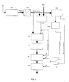
- a television receiver TVE - referred to in the English as a TV tuner - by means of an antenna A television signals, which it converts into the so-called color blanking sync signal, abbreviated composite signal.
- the composite signal often also referred to as CVBS signal after the English term Composite Video and Burst Synchronization, is supplied to the input of an analog-to-digital converter AD, whose output signal - the digitized CVBS signal - the input of a synchronizing pulse separator SIS and the first input of a comparator VL supplied at whose second input a reference variable RG is located.
- the output of the comparator VL is connected to the clock input of a counter Z1 whose reset input R is connected to the clock input T of a memory SP and the output of a controllable switch U and whose output is connected to the input of the memory SP.
- the line synchronization output of the synchronizing pulse separator SIS is connected to the input of a phase locked loop PLL whose output is connected to the first input of the controllable changeover switch U.
- the image synchronization output of the synchronizing pulse separator SIS is connected to the second input of the controllable changeover switch U.
- the analog-to-digital converter AD converts the analogue CVBS signal received by the television receiver TVE into a digital composite video signal.
- the comparator VL checks whether the pulses occurring in the FBAS signal exceed the predetermined reference value RG. If this is the case, the counter Z1 receives a count pulse. In this way, the glitches occurring in a line are counted whose amplitude and / or pulse width exceed the reference value RG.
- the counter Z1 is reset by the phase locked loop PLL with each horizontal synchronizing pulse, while the memory SP is clocked to take over the counter reading. In the memory SP, therefore, the measures of the lines can be stored.
- the controllable switch is switched to the other position B, then the counter Z1 is reset with each vertical synchronization pulse and the memory SP is clocked to take over the counter reading. In this case, the total dimensions for half or full images are stored in the memory SP.
- the composite video signal contains, between the two horizontal synchronizing pulses H of one line, by way of example three narrow interfering pulses S1, S2 and S3 and a broad interfering pulse E which is an echo of a horizontal synchronizing pulse.
- the output of the comparator VL contains only the two horizontal sync pulses H, the glitches S1, S2 and E, because the glitch S3 is hidden because its amplitude does not exceed the reference size RG.
- the counter Z1 therefore only counts the falling edges of the glitches S1, S2 and E.
- the sync pulse separator generates in addition to the two horizontal sync pulses H and the interfering echo pulse E.
- the PLL is filtered out by the phase locked loop, because it passes only regularly recurring pulses or . generated.
- the phase locked loop replaces missing horizontal sync pulses.
- this requires a relatively narrow catch area.
- a counter or buffer Z2 and a processor P are provided instead of the counter Z1, a counter or buffer Z2 and a processor P.
- the output of the analog-to-digital converter AD is connected to the input of the first latch Z2 whose clock input is connected to the output of the comparator VL and whose output is connected to the input of the processor P.
- the output of the processor P is connected to the input of the summer SU, which may also be integrated in the processor P.
- the latch Z2 stores the amplitudes of the glitches S1, S2 and E by adding or integrating them or forwarding them one by one to the processor P, where the amplitudes of the glitches can be weighted by factors.
- the measures of the individual lines or half or full frames obtained from the amplitudes of the glitches are stored, depending on the position of the controllable switch U.
- the third exemplary embodiment of a circuit arrangement illustrated in FIG. 3 differs from the second exemplary embodiment shown in FIG. 2 in that the buffer Z2 is replaced by a counter Z3 and a clock generator CL.
- the output of the comparator VL is connected to the enable input of the counter or buffer Z3 whose clock input T is connected to the clock generator CL and whose output is connected to the input of the processor P.
- the latch Z3 stores the pulse widths of the glitches S1, S2 and E by adding them to a total pulse width, or individually to the processor P where they can be weighted with factors prior to addition.
- the memory SP obtained from the pulse widths of the glitches measures the individual lines or half or frames are stored, depending on the position of the controllable switch U.
- the construction is correct with respect to the antenna A, the television receiver TVE, the analog-to-digital converter AD, the comparator VL, the synchronizing pulse separator SIS, the phase locked loop PLL, the controllable changeover switch U, of the memory SP, the summer SU and the processor P with the circuit arrangements of Figures 2 and 3.
- the input of the processor P is connected to the output of a counter or latch Z4 whose input is connected to the output of a counter Z5 and whose clock input T is connected to the output of the comparator VL.
- the input of the counter Z5 is connected to the output of a clock generator CL; the reset input of the counter Z5, like the first input of the controllable switch U, is connected to the output of the phase-locked loop PLL.
- the latch Z4 takes over the count of the counter Z5 clocked by the clock generator CL, which corresponds to the respective position of the individual interference pulses S1, S2 and E.
- These counter readings representing the positions of the glitches are weighted in the processor P by factors; in the summer SU, the weighted values generated in this way are obtained Measured numbers added and - depending on the position of the controllable switch U - stored for lines, half or full frames.
- FIG. 5 fifth embodiment of a circuit arrangement is a combination of the first 4 shown in Figures 1-4 embodiments.
- the output of the counter Z1 and the outputs of the counters Z2, Z3 and Z4 are connected to the inputs of the processor P.
- the processor P weightes the items provided by the counter Z4 with factors and passes them to the summer SU for addition with the numerals provided by the counters Z1-Z3, where they are summed.
- the individual pulse widths and / or the amplitudes corresponding numerical measures of the counters Z2 and Z3 can also be weighted with factors before the addition.
- the processor P the sums of the unweighted amplitudes and / or pulse widths can be weighted with factors. But even the sums of the already weighted amplitudes and / or pulse widths can be weighted again with factors. Every conceivable combination of weighting is possible.
- the counters Z2 and Z3 can be designed as digital counters or, if the analog-to-digital converter AD is not provided, as an integrator.
- the summer SU and the memory SP may be integrated in the processor P.
- the invention is particularly well suited for diversity reception systems with multiple television receivers, because the invention provides a meaningful criterion for image quality.
- inventively generated measures and overall measures for the evaluation of the image quality of the individual built in a diversity reception system television receiver can be easily determine the television receiver with the best picture quality and select the reception.
- Switching to the television receiver with the best picture can be done line by line, half picture or frame by frame.
- the smallest total size television receiver produces the best picture while the one with the largest overall size provides the lowest quality picture.
- the invention for a mobile diversity reception system z.
- a mobile diversity reception system z.
- the invention is also suitable for television receivers and video recorders if an evaluation of the picture quality is required for some reason.
Description
Die Erfindung betrifft eine Schaltungsanordnung zur Bestimmung der Qualität eines Videosignals und/oder eines Fernsehbildes.The invention relates to a circuit arrangement for determining the quality of a video signal and / or a television picture.
Der Empfang und die Wiedergabe von Fernsehbildern, in ortsfesten Empfangsstationen bereitet kaum Schwierigkeiten, weil die Empfangsverhältnisse gut sind und weitgehend konstant bleiben. Dagegen können die Empfangsverhältnisse für eine mobile Empfangsstation je nach Beschaffenheit des Geländes erheblich schwanken. Befindet sich die mobile Empfangsstation z. B. in einer bergigen Landschaft, können Echos den Empfang erheblich stören; im Funkschatten von Bergen oder Hügeln kann die Funkverbindung sogar vollständig zusammenbrechen, so daß anstelle eines Fernsehbildes nur noch Rauschen auf dem Bildschirm zu sehen ist.The reception and reproduction of television pictures, in stationary receiving stations hardly causes any difficulties, because the reception conditions are good and remain largely constant. In contrast, the reception conditions for a mobile receiving station can vary considerably depending on the nature of the terrain. Is the mobile receiving station z. B. in a mountainous landscape, echoes can significantly disturb the reception; in the radio shadow of mountains or hills, the radio connection can even collapse completely, so that instead of a television picture only noise can be seen on the screen.
Inzwischen werden Kraftfahrzeuge, wie z. B. PKW und Reisebusse, aber auch Eisenbahnfahrzeuge, mit Fernsehempfängern und Bildschirmen ausgerüstet, um einerseits Nachrichten, beispielsweise über Videotext übermittelte Verkehrsmeldungen, anzeigen oder andererseits die Reisenden mit Fernsehprogrammen unterhalten zu können. Aufgrund der infolge des gerade befahrenen Geländes unter Umständen erheblich schwankenden Empfangsverhältnisse in einer sich bewegenden Empfangsstation werden die Augen der reisenden Fernsehzuschauer in unangenehmer Weise stark beansprucht, weil die Bildqualität in erheblichem Maße schwanken kann. Durchfährt das Fahrzeug z. B. einen Funkschatten, so sieht der Betrachter nur noch Rauschen auf dem Bildschirm Das Betrachten eines Fernsehprogramms mit derartigen Störungen führt eher zur Ermüdung der Zuschauer als daß es deren Unterhaltung dient.Meanwhile, motor vehicles, such. As cars and coaches, but also railway vehicles, equipped with television receivers and screens to on the one hand news, for example, via teletext transmitted traffic reports, or on the other hand to entertain the travelers with television programs. Due to the due to the currently busy terrain under certain circumstances significantly fluctuating reception conditions in a moving receiving station, the eyes of the traveling television viewers are heavily used in an unpleasant manner, because the image quality can vary considerably. Passes the vehicle z. B. a radio shadow, the viewer sees only noise on the screen viewing a television program with such interference leads rather to the fatigue of the audience than that it serves their entertainment.
Es ist bekannt, den Empfang von Funksignalen in mobilen Empfangsstationen durch Mehrwegeempfang, im englischen als Diversity bezeichnet, zu verbessern. Unter Antennen-Diversity versteht man, daß ein Empfänger an eine von mehreren, meist räumlich getrennten Antennen anschließbar ist, während mit Frequenz-Diversity ein System aus mehreren Empfängern bezeichnet wird, die auf unterschiedlichen Frequenzen gleiche Signale oder dieselben Programme empfangen. Unter Raum-Diversity versteht man ein System aus mehreren Empfängern, die mit räumlich getrennten Antennen gleiche Signale empfangen.It is known to improve the reception of radio signals in mobile receiving stations by multipath reception, referred to in English as diversity. Antenna diversity is understood to mean that a receiver can be connected to one of several, usually spatially separated, antennas while using frequency diversity System is called from multiple receivers that receive the same signals or the same programs on different frequencies. Room diversity is a system consisting of several receivers that receive the same signals with spatially separated antennas.
Um in einer Diversity-Empfangsanlage mit mehreren Empfängern den Empfänger mit dem besten Empfang auszählen zu können, ist ein aussagekräftiges Kriterium erforderlich.In order to be able to count the receiver with the best reception in a diversity reception system with several receivers, a meaningful criterion is required.
Die US 5 777 693 A offenbart eine Diversity-Empfangsanlage für eine sich bewegende Einheit, beispielsweise ein Fahrzeug.US 5 777 693 A discloses a diversity receiving system for a moving unit, such as a vehicle.
Der US 4 636 860 A ist eine Vorrichtung zu entnehmen, welche das Noise-Signal derart auswertet, dass die Zahl der Impulse, welche einen vorgegebenen Wert überschreiten, gezählt wird.US Pat. No. 4,636,860 A discloses a device which evaluates the noise signal such that the number of pulses exceeding a predetermined value is counted.
Aus der US 5,303,396 ist bekannt, dass die Breite der Störimpulse ein wichtiger Parameter für die Bildqualität ist.It is known from US Pat. No. 5,303,396 that the width of the glitches is an important parameter for the image quality.
Es ist daher Aufgabe der Erfindung, eine demgegenüber verbesserte Schaltungsanordnung zur Bestimmung der Qualität eines Videosignals und/oder eines Fernsehbildes anzugeben.It is therefore an object of the invention to provide a contrast improved circuit arrangement for determining the quality of a video signal and / or a television picture.
Die Erfindung geht von der ersten Erkenntnis aus, dass in einer Zeile nach dem Horizontal-Synchronimpuls auftretende Störimpulse als Maß für die Bildqualität dienen können. Die Erfindung geht weiter von der zweiten Erkenntnis aus, dass die Anzahl der Störimpulse je Zeile sowie weitere die Störimpulse kennzeichnende Parameter, wie Amplitude, Impulsbreite und Position der Störimpulse, innerhalb einer Zeile wichtige, die Bildqualität bestimmende physikalische Größen sind.The invention is based on the first finding that glitches occurring in a line after the horizontal sync pulse can serve as a measure of the image quality. The invention further proceeds from the second finding that the number of glitches per line as well as further parameters characterizing the glitches, such as amplitude, pulse width and position of the glitches, are important physical quantities determining image quality within a row.
Die Erfindung löst diese Aufgabe durch die Schaltungsanordnung gemäß Anspruch 1.The invention solves this problem by the circuit arrangement according to
Diese Lösung beruht auf der Erkenntnis, dass Fälle auftreten können, wo der Empfänger mit der geringsten Anzahl an Störimpulsen je Zeile ein schlechteres Bild liefert als z. B. ein anderer Empfänger mit mehr Störimpulsen je Zeile, weil neben der Anzahl der Impulse auch deren Breite die Bildqualität beeinflussen. In einer Diversity-Empfangsanlage kann der Empfänger mit der geringsten Anzahl an Störimpulsen ein weniger gutes Bild liefern als ein anderer, wenn die Impulsbreiten beim Empfänger mit der geringsten Anzahl an Störimpulsen größer sind als beim anderen.This solution is based on the recognition that cases may occur where the receiver with the least number of glitches per line delivers a worse picture than z. B. another receiver with more glitches per line, because in addition to the number of pulses and their width affect the image quality. In a diversity receiving system, the receiver with the least amount of glitches can provide a less good picture than another if the pulse widths are greater at the receiver with the fewest glitches than at the other.
Gemäß der Erfindung werden die in einer Zeile detektierten Störimpulse gezählt. Die Anzahl der Störimpulse ist daher ein Maß oder besser gesagt eine Maßzahl für die Bildqualität.According to the invention, the interference pulses detected in one line are counted. The number of glitches is therefore a measure or better a measure of the image quality.
Wenn z. B. in einer Diversity-Empfangsanlage mehrere Empfänger Fernsehsignale des gleichen Programms empfangen, stellt die Anzahl der bei den einzelnen Empfängern detektierten Störimpulse je Zeile eine Maßzahl für die Bildqualität dar. Es kann daher der Empfänger mit der jeweils geringsten Anzahl an Störimpulsen je Zeile ausgewählt werden. Beispielsweise kann für jeden Empfänger ein Zähler vorgesehen werden, der die Störimpulse innerhalb einer Zeile zählt. Als Empfänger mit dem augenblicklich besten Bild kann dann jeweils der Empfänger mit der geringsten Anzahl an Störimpulsen ausgewählt werden.If z. B. received in a diversity reception system multiple receiver television signals of the same program, the number of detected at each receiver glitches per line is a measure of the image quality. It can therefore be selected with the lowest number of glitches per line receiver , For example, a counter can be provided for each receiver, which counts the glitches within a line. As a receiver with the currently best picture, the receiver with the lowest number of glitches can be selected.
Es können aber auch Fälle auftreten, wo der Empfänger mit der geringsten Anzahl an Störimpulsen je Zeile ein schlechteres Bild liefert als z. B. ein anderer Empfänger mit mehr Störimpulsen je Zeile, weil neben der Anzahl der Impulse auch deren Amplitude die Bildqualität beeinflussen. Wenn z. B. bei einem Empfänger viele Störimpulse geringer Amplitude auftreten, während dagegen beim Empfänger mit der geringsten Anzahl an Störimpulsen je Zeile die Störimpulse größere Amplituden aufweisen, kann der Empfänger mit der größeren Anzahl an Störimpulsen ein besseres Bild liefern als der Empfänger mit weniger Störimpulsen je Zeile, aber größerer Amplitude.But there may also be cases where the receiver with the least number of glitches per line delivers a worse picture than z. B. another receiver with more glitches per line, because in addition to the number of pulses and their amplitude affect the image quality. If z. B. at a receiver many glitches of low amplitude occur, while against the receiver with the least number of Spurious pulses per line, the glitches have larger amplitudes, the receiver with the larger number of glitches can provide a better picture than the receiver with fewer glitches per line, but larger amplitude.
Die Erfindung wird nun näher anhand der in den Figuren dargestellten Ausführungsbeispiele von Schaltungsanordnungen zur Durchführung des erfindungsgemäßen Verfahrens erläutert.The invention will now be explained in more detail with reference to the embodiments of circuit arrangements for carrying out the method according to the invention shown in FIGS.
Es zeigen
Figur 1 ein erstes Ausführungsbeispiel einer Schaltungsanordnung,Figur 2 ein zweites Ausführungsbeispiel einer Schaltungsanordnung,Figur 3 ein drittes Ausführungsbeispiel einer Schaltungsanordnung,- Figur 4 ein viertes Ausführungsbeispiel einer Schaltungsanordnung,
- Figur 5 ein fünftes Ausführungsbeispiel einer Schaltungsanordnung,
- Figur 6 ein Impulsdiagramm.
- FIG. 1 shows a first exemplary embodiment of a circuit arrangement,
- FIG. 2 shows a second exemplary embodiment of a circuit arrangement,
- FIG. 3 shows a third exemplary embodiment of a circuit arrangement,
- FIG. 4 shows a fourth exemplary embodiment of a circuit arrangement,
- FIG. 5 shows a fifth exemplary embodiment of a circuit arrangement,
- FIG. 6 is a timing diagram.
In der Figur 1 empfängt ein Fernsehempfänger TVE - im englischen als TV-Tuner bezeichnet - mittels einer Antenne A Fernsehsignale, die er in das sogenannte Farbbildaustastsynchronsignal, abgekürzt FBAS-Signal wandelt. Das FBAS-Signal, häufig auch nach der englischen Bezeichnung Composit Video and Burst Synchronization als CVBS-Signal bezeichnet, wird dem Eingang eines Analog-Digital-Wandlers AD zugeführt, dessen Ausgangssignal - das digitalisierte FBAS-Signal - dem Eingang eines Synchronimpulsseparators SIS und dem ersten Eingang eines Vergleichers VL zugeführt wird, an dessen zweitem Eingang eine Referenzgröße RG liegt. Der Ausgang des Vergleichers VL ist mit dem Takteingang eines Zählers Z1 verbunden, dessen Rücksetzeingang R mit dem Takteingang T eines Speichers SP und dem Ausgang eines steuerbaren Umschalters U und dessen Ausgang mit dem Eingang des Speichers SP verbunden ist. Der Zeilensynchronisationsausgang des Synchronimpulsseparators SIS ist mit dem Eingang einer Phasenregelschleife PLL verbunden, deren Ausgang mit dem ersten Eingang des steuerbaren Umschalters U verbunden ist. Der Bildsynchronisationsausgang des Synchronimpulsseparators SIS ist mit dem zweiten Eingang des steuerbaren Umschalters U verbunden.In Figure 1, a television receiver TVE - referred to in the English as a TV tuner - by means of an antenna A television signals, which it converts into the so-called color blanking sync signal, abbreviated composite signal. The composite signal, often also referred to as CVBS signal after the English term Composite Video and Burst Synchronization, is supplied to the input of an analog-to-digital converter AD, whose output signal - the digitized CVBS signal - the input of a synchronizing pulse separator SIS and the first input of a comparator VL supplied at whose second input a reference variable RG is located. The output of the comparator VL is connected to the clock input of a counter Z1 whose reset input R is connected to the clock input T of a memory SP and the output of a controllable switch U and whose output is connected to the input of the memory SP. The line synchronization output of the synchronizing pulse separator SIS is connected to the input of a phase locked loop PLL whose output is connected to the first input of the controllable changeover switch U. The image synchronization output of the synchronizing pulse separator SIS is connected to the second input of the controllable changeover switch U.
Der Analog-Digital-Wandler AD wandelt das vom Fernsehempfänger TVE empfangene analoge FBAS-Signal in ein digitales FBAS-Signal. Der Vergleicher VL prüft, ob die im FBAS-Signal auftretenden Impulse die vorgegebene Referenzgröße RG überschreiten. Ist dies der Fall, erhält der Zähler Z1 einen Zählimpuls. Auf diese Weise werden diejenigen in einer Zeile auftretenden Störimpulse gezählt, deren Amplitude und/oder Impulsbreite die Referenzgröße RG überschreiten. Bei der in der Figur 1 gezeigten Stellung Z des steuerbaren Umschalters U wird der Zähler Z1 mit jedem Horizontal-Synchronimpuls von der Phasenregelschleife PLL zurückgesetzt, während der Speicher SP zur Übernahme des Zählerstandes getaktet wird. Im Speicher SP können daher die Maßzahlen der Zeilen gespeichert werden.The analog-to-digital converter AD converts the analogue CVBS signal received by the television receiver TVE into a digital composite video signal. The comparator VL checks whether the pulses occurring in the FBAS signal exceed the predetermined reference value RG. If this is the case, the counter Z1 receives a count pulse. In this way, the glitches occurring in a line are counted whose amplitude and / or pulse width exceed the reference value RG. In the position Z of the controllable changeover switch U shown in FIG. 1, the counter Z1 is reset by the phase locked loop PLL with each horizontal synchronizing pulse, while the memory SP is clocked to take over the counter reading. In the memory SP, therefore, the measures of the lines can be stored.
Wird der steuerbare Umschalter in die andere Stellung B geschaltet, so wird der Zähler Z1 mit jedem Vertikalsynchronimpuls zurückgesetzt und der Speicher SP zur Übernahme des Zählerstandes getaktet. In diesem Fall werden im Speicher SP die Gesamtmaßzahlen für Halb- oder Vollbilder gespeichert.If the controllable switch is switched to the other position B, then the counter Z1 is reset with each vertical synchronization pulse and the memory SP is clocked to take over the counter reading. In this case, the total dimensions for half or full images are stored in the memory SP.
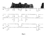
In der Figur 6 sind Impulsdiagramme gezeigt.In the figure 6 timing diagrams are shown.
Das FBAS-Signal enthält zwischen den beiden Horizontal-Synchronimpulsen H einer Zeile beispielhaft drei schmale Störimpulse S1, S2 und S3 sowie einen breiten Störimpuls E, der ein Echo eines Horizontal-Synchronimpulses ist.The composite video signal contains, between the two horizontal synchronizing pulses H of one line, by way of example three narrow interfering pulses S1, S2 and S3 and a broad interfering pulse E which is an echo of a horizontal synchronizing pulse.
Das Ausgangssignal des Vergleichers VL enthält nur noch die beiden Horizontal-Synchronimpulse H, die Störimpulse S1, S2 und E, denn der Störimpuls S3 wird ausgeblendet, weil seine Amplitude die Referenzgröße RG nicht überschreitet.The output of the comparator VL contains only the two horizontal sync pulses H, the glitches S1, S2 and E, because the glitch S3 is hidden because its amplitude does not exceed the reference size RG.
Der Zähler Z1 zählt daher nur die fallenden Flanken der Störimpulse S1, S2 und E. Der Synchronimpulsseparator erzeugt neben den beiden Horizontal-Synchronimpulsen H auch den störenden Echoimpuls E. der jedoch von der Phasenregelschleife PLL herausgefiltert wird, weil sie nur regelmäßig wiederkehrende Impulse durchläßt bzw. erzeugt. Außerdem ersetzt die Phasenregelschleife fehlende Horizontal-Synchronimpulse. Voraussetzung hierfür ist allerdings ein verhältnismäßig eng eingestellter Fangbereich.The counter Z1 therefore only counts the falling edges of the glitches S1, S2 and E. The sync pulse separator generates in addition to the two horizontal sync pulses H and the interfering echo pulse E. However, the PLL is filtered out by the phase locked loop, because it passes only regularly recurring pulses or . generated. In addition, the phase locked loop replaces missing horizontal sync pulses. However, this requires a relatively narrow catch area.
Bei dem in der Figur 2 abgebildeten zweiten Ausführungsbeispiel einer Schaltungsanordnung sind anstelle des Zählers Z1 ein Zähler bzw. Zwischenspeicher Z2 und ein Prozessor P vorgesehen. Der Ausgang des Analog-Digital-Wandlers AD ist mit dem Eingang des ersten Zwischenspeichers Z2 verbunden, dessen Takteingang mit dem Ausgang des Vergleichers VL verbunden ist und dessen Ausgang mit dem Eingang des Prozessors P verbunden ist. Der Ausgang des Prozessors P ist mit dem Eingang des Summierers SU verbunden, der auch im Prozessor P integriert sein kann.In the case of the second exemplary embodiment of a circuit arrangement shown in FIG. 2, instead of the counter Z1, a counter or buffer Z2 and a processor P are provided. The output of the analog-to-digital converter AD is connected to the input of the first latch Z2 whose clock input is connected to the output of the comparator VL and whose output is connected to the input of the processor P. The output of the processor P is connected to the input of the summer SU, which may also be integrated in the processor P.
Der Zwischenspeicher Z2 speichert die Amplituden der Störimpulse S1, S2 und E, indem er sie addiert bzw. integriert oder sie einzeln an den Prozessor P weiterleitet, wo die Amplituden der Störimpulse mit Faktoren gewichtet werden können. Im Speicher SP werden die aus den Amplituden der Störimpulse gewonnenen Maßzahlen der einzelnen Zeilen oder Halb- bzw. Vollbilder gespeichert, je nach Stellung des steuerbaren Umschalters U.The latch Z2 stores the amplitudes of the glitches S1, S2 and E by adding or integrating them or forwarding them one by one to the processor P, where the amplitudes of the glitches can be weighted by factors. In the memory SP, the measures of the individual lines or half or full frames obtained from the amplitudes of the glitches are stored, depending on the position of the controllable switch U.
Das in der Figur 3 dargestellte dritte Ausführungsbeispiel einer Schaltungsanordnung unterscheidet sich von dem in der Figur 2 gezeigten zweiten Ausführungsbeispiel dadurch, daß der Zwischenspeicher Z2 durch einen Zähler bzw. Zwischenspeicher Z3 und einen Taktgenerator CL ersetzt ist.The third exemplary embodiment of a circuit arrangement illustrated in FIG. 3 differs from the second exemplary embodiment shown in FIG. 2 in that the buffer Z2 is replaced by a counter Z3 and a clock generator CL.
Anstelle des Ausgangs des Analog-Digital-Wandlers AD ist der Ausgang des Vergleichers VL mit dem Freigabeeingang des Zählers bzw. Zwischenspeichers Z3 verbunden, dessen Takteingang T mit dem Taktgenerator CL und dessen Ausgang mit dem Eingang des Prozessors P verbunden ist.Instead of the output of the analog-to-digital converter AD, the output of the comparator VL is connected to the enable input of the counter or buffer Z3 whose clock input T is connected to the clock generator CL and whose output is connected to the input of the processor P.
Der Zwischenspeicher Z3 speichert die Impulsbreiten der Störimpulse S1, S2 und E, indem er sie zu einer Gesamtimpulsbreite addiert bzw. integriert oder einzeln an den Prozessor P weiterleitet, wo sie vor der Addition mit Faktoren gewichtet werden können. Im Speicher SP werden die aus den Impulsbreiten der Störimpulse gewonnenen Maßzahlen der einzelnen Zeilen oder Halb- bzw. Vollbilder gespeichert, je nach Stellung des steuerbaren Umschalters U.The latch Z3 stores the pulse widths of the glitches S1, S2 and E by adding them to a total pulse width, or individually to the processor P where they can be weighted with factors prior to addition. In the memory SP obtained from the pulse widths of the glitches measures the individual lines or half or frames are stored, depending on the position of the controllable switch U.
Bei dem in der Figur 4 gezeigten vierten Ausführungsbeispiel einer Schaltungsanordnung stimmt der Aufbau bezüglich der Antenne A, des Fernsehempfängers TVE, des Analog-Digital-Wandlers AD, des Vergleichers VL, des Synchronimpulsseparators SIS, der Phasenregelschleife PLL, des steuerbaren Umschalters U, des Speichers SP, des Summierers SU und des Prozessors P mit den Schaltungsanordnungen der Figuren 2 und 3 überein. Der Eingang des Prozessors P ist jedoch mit dem Ausgang eines Zählers bzw. Zwischenspeichers Z4 verbunden, dessen Eingang mit dem Ausgang eines Zählers Z5 und dessen Takteingang T mit dem Ausgang des Vergleichers VL verbunden ist. Der Eingang des Zählers Z5 ist mit dem Ausgang eines Taktgenerators CL verbunden; der Rücksetzeingang des Zählers Z5 ist ebenso wie der erste Eingang des steuerbaren Umschalters U mit dem Ausgang der Phasenregelschleife PLL verbunden.In the case of the fourth exemplary embodiment of a circuit arrangement shown in FIG. 4, the construction is correct with respect to the antenna A, the television receiver TVE, the analog-to-digital converter AD, the comparator VL, the synchronizing pulse separator SIS, the phase locked loop PLL, the controllable changeover switch U, of the memory SP, the summer SU and the processor P with the circuit arrangements of Figures 2 and 3. However, the input of the processor P is connected to the output of a counter or latch Z4 whose input is connected to the output of a counter Z5 and whose clock input T is connected to the output of the comparator VL. The input of the counter Z5 is connected to the output of a clock generator CL; the reset input of the counter Z5, like the first input of the controllable switch U, is connected to the output of the phase-locked loop PLL.
Mit jedem am Ausgang des Vergleichers VL abgegebenen Impuls übernimmt der Zwischenspeicher Z4 den Zählerstand des vom Taktgenerator CL getakteten Zählers Z5, welcher der jeweiligen Position der einzelnen Störimpulse S1, S2 und E entspricht. Diese die Positionen der Störimpulse repräsentierenden Zählerstände werden im Prozessor P mit Faktoren gewichtet; im Summierer SU werden die auf diese Weise erzeugten gewichteten Maßzahlen addiert und - je nach Stellung des steuerbaren Umschalters U - für Zeilen, Halb- oder Vollbilder gespeichert.With each pulse delivered at the output of the comparator VL, the latch Z4 takes over the count of the counter Z5 clocked by the clock generator CL, which corresponds to the respective position of the individual interference pulses S1, S2 and E. These counter readings representing the positions of the glitches are weighted in the processor P by factors; in the summer SU, the weighted values generated in this way are obtained Measured numbers added and - depending on the position of the controllable switch U - stored for lines, half or full frames.
Das in der Figur 5 abgebildete fünfte Ausführungsbeispiel einer Schaltungsanordnung stellt eine Kombination der in den Figuren 1 - 4 gezeigten ersten 4 Ausführungsbeispiele dar.The illustrated in Figure 5 fifth embodiment of a circuit arrangement is a combination of the first 4 shown in Figures 1-4 embodiments.
Der Ausgang des Zählers Z1 und die Ausgänge der Zähler bzw. Zwischenspeicher Z2, Z3 und Z4 sind mit den Eingängen des Prozessors P verbunden.The output of the counter Z1 and the outputs of the counters Z2, Z3 and Z4 are connected to the inputs of the processor P.
Der Prozessor P gewichtet die vom Zähler Z4 gelieferten Positionen bzw. Maßzahlen mit Faktoren und leitet sie mit den von den Zählern Z1 - Z3 gelieferten Maßzahlen zur Addition an den Summierer SU, wo sie summiert werden. Im Prozessor P können aber auch die einzelnen den Impulsbreiten und/oder den Amplituden entsprechenden Maßzahlen der Zähler Z2 und Z3 vor der Addition mit Faktoren gewichtet werden. Neben einer Gewichtung der einzelnen Amplituden und Impulsbreiten können im Prozessor P die Summen der ungewichteten Amplituden und/oder Impulsbreiten mit Faktoren gewichtet werden. Doch auch die Summen der bereits gewichteten Amplituden und/oder Impulsbreiten können nochmals mit Faktoren gewichtet werden. Es ist jede denkbare Kombination der Gewichtung möglich.The processor P weightes the items provided by the counter Z4 with factors and passes them to the summer SU for addition with the numerals provided by the counters Z1-Z3, where they are summed. In the processor P, however, the individual pulse widths and / or the amplitudes corresponding numerical measures of the counters Z2 and Z3 can also be weighted with factors before the addition. In addition to a weighting of the individual amplitudes and pulse widths, in the processor P the sums of the unweighted amplitudes and / or pulse widths can be weighted with factors. But even the sums of the already weighted amplitudes and / or pulse widths can be weighted again with factors. Every conceivable combination of weighting is possible.
Die Zähler bzw. Zwischenspeicher Z2 und Z3 können als digitale Zähler oder, wenn der Analog-Digital-Wandler AD nicht vorgesehen ist, als Integrator ausgeführt sein. Der Summierer SU und der Speicher SP können im Prozessor P integriert sein.The counters Z2 and Z3 can be designed as digital counters or, if the analog-to-digital converter AD is not provided, as an integrator. The summer SU and the memory SP may be integrated in the processor P.
Für normale Fernsehsendungen ist es sinnvoll, die im Bereich der Bildmitte auftretenden Störimpulse und deren Parameter stärker zu gewichten als die in den Randbereichen liegenden Störimpulse.For normal television broadcasts, it makes sense to weight the interference impulses occurring in the center of the image and their parameters more strongly than the interfering impulses lying in the peripheral areas.
Dagegen ist es beim Betrachten von Fernsehsendungen mit Untertiteln, wie z. B. bei Spielfilmen mit Untertitel und bei Programmen mit Videotext für Gehörlose sinnvoll, die im Bereich der Untertitel liegenden Störimpulse und deren Parameter stärker zu gewichten.In contrast, it is when viewing television programs with subtitles, such. For example, in the case of feature films with subtitles and programs with teletext for the deaf, it makes sense to give greater weight to the interference impulses and their parameters in the area of the subtitles.
Die Erfindung ist besonders gut für Diversity-Empfangsanlagen mit mehreren Fernsehempfängern geeignet, weil die Erfindung ein aussagekräftiges Kriterium für die Bildqualität liefert. Mittels der erfindungsgemäß erzeugten Maßzahlen und Gesamtmaßzahlen zur Bewertung der Bildqualität der einzelnen in einer Diversity-Empfangsanlage eingebauten Fernsehempfänger läßt sich auf einfache Art und Weise der Fernsehempfänger mit der besten Bildqualität feststellen und zum Empfang auswählen.The invention is particularly well suited for diversity reception systems with multiple television receivers, because the invention provides a meaningful criterion for image quality. By means of the inventively generated measures and overall measures for the evaluation of the image quality of the individual built in a diversity reception system television receiver can be easily determine the television receiver with the best picture quality and select the reception.
Die Umschaltung auf den Fernsehempfänger mit dem jeweils besten Bild kann zeilen-, halbbild- oder vollbildweise erfolgen. Derjenige Fernsehempfänger mit der kleinsten Gesamtmaßzahl erzeugt das beste Bild, während derjenige mit der größten Gesamtmaßzahl das Bild mit der geringsten Qualität liefert.Switching to the television receiver with the best picture can be done line by line, half picture or frame by frame. The smallest total size television receiver produces the best picture while the one with the largest overall size provides the lowest quality picture.
Insbesondere ist die Erfindung für eine mobile Diversity-Empfangsanlage z. B. in einem PKW, Reisebus oder Eisenbahnfahrzeug, geeignet, weil wie eingangs beschrieben, bei einer mobilen Anlage die Empfangsverhältnisse je nach Art des befahrenen Geländes starken Schwankungen unterliegen. Doch auch für Fernsehempfänger und Videorecorder ist die Erfindung geeignet, wenn eine Bewertung der Bildqualität aus irgendwelchen Gründen erforderlich ist.In particular, the invention for a mobile diversity reception system z. As in a car, coach or railway vehicle, suitable, because as described above, the reception conditions are subject to strong fluctuations in a mobile system depending on the type of terrain used. However, the invention is also suitable for television receivers and video recorders if an evaluation of the picture quality is required for some reason.
Claims (9)
- A circuit arrangement to evaluate the image quality of a television image, whereby the occurrence of noise pulses in a line is detected after the horizontal synchronisation pulse and evaluated with respect to its parameters in order to obtain a measurement of the quality of a video signal, characterised in that an FBAS [composite-video] signal (FBAS) is supplied as the input to a synchronisation-pulse separator (SIS), and as a first input to a comparator (VL), at whose second input a reference amplitude (RG) is applied, that the horizontal synchronisation pulse output from the synchronisation-pulse separator (SIS) is connected to the input of a phase-locked loop (PLL), that the output of the phase-locked loop (PLL) or the vertical synchronisation output of the synchronisation-pulse separator (SIS) is connected to the clock input of a memory (SP), that the output of the comparator (VL) is connected to release input of a counter (Z3) and to the clock input of an adder (SU), that the output of a clock generator (CL) is connected to the clock input of the counter (Z3) to count or integrate the pulse width of the detected noise pulse, whose output is connected to the input of a processor (P), and that the output of the processor (P) is connected to the input of the adder (SU), whose output is connected with the data input of the memory (SP).
- A circuit arrangement according to claim 1, characterised in that the output of the phase-locked loop (PLL) or the vertical synchronisation output of the synchronisation-pulse separator (SIS) is connected to the reset input of a second counter (Z1) to count the noise pulses, whose clock input is connected to the output of the comparator (VL).
- A circuit arrangement according to claim 1 or 2, characterised in that the output of the phase-locked loop (PLL) or the vertical synchronisation output of the synchronisation-pulse separator (SIS) is connected to the reset input of the adder (SU), that the FBAS video signal (FBAS) is attached to the input of a first buffer memory (Z2), whose clock input is connected to the output of the comparator (VL) and whose output is connected to the input of a processor (P).
- A circuit arrangement according to claim 3, characterised in that the first buffer memory (Z2) is provided with a digital memory or a sampling or holding element.
- A circuit arrangement according to claims 1 to 4, characterised in that the pulse widths are summed up using a digital counter (Z3) or integrated using an integrator.
- A circuit arrangement according to one of the claims 1 to 5, characterised in that the output of the comparator (VL) is connected to the clock input of a second buffer memory (Z4) and of the adder (SU), that the output of the phase-locked loop (PLL) is connected to the reset input of a third counter (Z5), that the vertical synchronisation output of the synchronisation-pulse separator (SIS) or the output of the phase-locked loop (PLL) is connected to the reset input of the adder (SU), that the output of the clock generator (CL) is connected to the clock input of the third counter (Z5), whose output is connected to the input of the second buffer memory (Z4), that the output of the second buffer memory (Z4) is connected to the input of the processor (P).
- A circuit arrangement according to one of the claims 1 to 6, characterised in that the output of the phase-locked loop (PLL) is connected to the first input of a controllable switch (U), and the vertical synchronisation output of the synchronisation-pulse separator (SIS) is connected to the second input the controllable switch (U), whose output is connected to the clock input of a memory (SP) and to the reset input of the adder (SU).
- A circuit arrangement according to one of the claims 1 to 7, characterised in that an analogue-to-digital converter (AD) is connected before the comparator (VL) and the synchronisation-pulse separator (SIS).
- A circuit arrangement according to one of the claims 1 to 8, characterised in that the FBAS signal (FBAS) is supplied by a television receiver (TVE).
Applications Claiming Priority (3)
| Application Number | Priority Date | Filing Date | Title |
|---|---|---|---|
| DE19743124 | 1997-09-30 | ||
| DE19743124A DE19743124B4 (en) | 1997-09-30 | 1997-09-30 | Method for determining the quality of a video signal and / or a television picture |
| PCT/DE1998/002904 WO1999017557A1 (en) | 1997-09-30 | 1998-09-30 | Method for determining the quality of a video and/or television image signal |
Publications (2)
| Publication Number | Publication Date |
|---|---|
| EP0941618A1 EP0941618A1 (en) | 1999-09-15 |
| EP0941618B1 true EP0941618B1 (en) | 2006-11-15 |
Family
ID=7844102
Family Applications (1)
| Application Number | Title | Priority Date | Filing Date |
|---|---|---|---|
| EP98955363A Expired - Lifetime EP0941618B1 (en) | 1997-09-30 | 1998-09-30 | Device for determining the quality of a television image signal |
Country Status (6)
| Country | Link |
|---|---|
| US (1) | US6441847B1 (en) |
| EP (1) | EP0941618B1 (en) |
| JP (1) | JP3811818B2 (en) |
| KR (1) | KR20000069200A (en) |
| DE (2) | DE19743124B4 (en) |
| WO (1) | WO1999017557A1 (en) |
Families Citing this family (12)
| Publication number | Priority date | Publication date | Assignee | Title |
|---|---|---|---|---|
| DE19929071A1 (en) * | 1999-06-25 | 2000-12-28 | Fuba Automotive Gmbh | Antenna diversity system, especially for mobile TV reception, has diversity circuit with n inputs, m outputs, each with receiver branch for generating complete antenna-specific video signals |
| DE10006701C2 (en) * | 2000-02-16 | 2002-04-11 | Harman Becker Automotive Sys | receiver |
| US6734898B2 (en) * | 2001-04-17 | 2004-05-11 | General Instrument Corporation | Methods and apparatus for the measurement of video quality |
| US6982745B2 (en) * | 2001-11-27 | 2006-01-03 | Sony Corporation | Antenna level display device and method, and receiving apparatus |
| US20040207643A1 (en) * | 2003-04-18 | 2004-10-21 | Bozidar Janko | Attention model enhanced video waveform monitor |
| DE102004020503A1 (en) * | 2004-04-26 | 2005-11-17 | Fuba Automotive Gmbh & Co. Kg | Process to receive pictures when mobile where pictures received from two antennae are decomposed into picture zones, then evaluated against quality criteria and reconstituted into an output picture on the screen |
| DE102004058541B4 (en) * | 2004-12-03 | 2006-10-05 | Lear Corporation Gmbh & Co. Kg | Method for noise reduction of digitized analog video signals |
| JP4896661B2 (en) * | 2006-10-26 | 2012-03-14 | オンセミコンダクター・トレーディング・リミテッド | Clock recovery circuit |
| US9197934B2 (en) * | 2012-05-17 | 2015-11-24 | Stmicroelectronics, Inc. | Fault tolerant system with equivalence processing driving fault detection and backup activation |
| CN105681780B (en) * | 2014-11-19 | 2018-06-15 | 深圳市中兴微电子技术有限公司 | A kind of measuring method and device of Composite Video Baseband Signal quality |
| KR102510446B1 (en) * | 2016-01-15 | 2023-03-15 | 삼성전자주식회사 | Display controller for generating video sync signal using external clock, application processor including the display controller, and electronic system including the display controller |
| US10085015B1 (en) * | 2017-02-14 | 2018-09-25 | Zpeg, Inc. | Method and system for measuring visual quality of a video sequence |
Citations (1)
| Publication number | Priority date | Publication date | Assignee | Title |
|---|---|---|---|---|
| US5303396A (en) * | 1990-06-13 | 1994-04-12 | Hitachi, Ltd. | Diversity reception having a plurality of antennas for use with moving vehicles |
Family Cites Families (36)
| Publication number | Priority date | Publication date | Assignee | Title |
|---|---|---|---|---|
| CH577765A5 (en) * | 1972-12-05 | 1976-07-15 | Hartig Gunter | |
| US4268858A (en) * | 1977-03-04 | 1981-05-19 | Westinghouse Electric Corp. | TV Transmission system for long tow cables |
| DE3110890C2 (en) * | 1981-03-20 | 1983-04-14 | Philips Patentverwaltung Gmbh, 2000 Hamburg | Circuit arrangement for vertical deflection in a television set |
| US4402013A (en) * | 1981-04-06 | 1983-08-30 | Rca Corporation | Video signal analyzer |
| DE3165054D1 (en) * | 1981-07-11 | 1984-08-30 | Itt Ind Gmbh Deutsche | Integrated circuit for television receivers comprising a synchronization signal separator circuit with a clamp level control circuit |
| US4471389A (en) * | 1982-03-01 | 1984-09-11 | Zenith Electronics Corporation | Interference pulse elimination in capacitance electronic disc systems |
| NL8302984A (en) * | 1983-08-26 | 1985-03-18 | Philips Nv | IMAGE DISPLAY WITH A NOISE DETECTOR. |
| GB2148673B (en) * | 1983-10-24 | 1987-09-09 | Philips Electronic Associated | A signal quality detector for a teletext television receiver |
| DE3541306C1 (en) * | 1985-11-22 | 1986-08-28 | Philips Patentverwaltung Gmbh, 2000 Hamburg | Circuit arrangement for a video recorder |
| US4682230A (en) * | 1986-03-21 | 1987-07-21 | Rca Corporation | Adaptive median filter system |
| JPS62272673A (en) * | 1986-05-20 | 1987-11-26 | Sanyo Electric Co Ltd | Noise reducer |
| DE3715929A1 (en) * | 1987-05-13 | 1988-11-24 | Thomson Brandt Gmbh | CIRCUIT FOR THE AUTOMATIC SWITCHING OF THE CONTROL SPEED OF A PHASE CONTROL CIRCUIT |
| JPS63304728A (en) * | 1987-06-05 | 1988-12-13 | Mitsubishi Electric Corp | Reception antenna switching/selecting device |
| JPH02159886A (en) * | 1988-12-13 | 1990-06-20 | Clarion Co Ltd | Television diversity receiver |
| US4873574A (en) * | 1988-12-20 | 1989-10-10 | North American Philips Corporation | Noise measurement for video signals |
| DE3926336C2 (en) * | 1989-08-09 | 2001-03-29 | Heinz Lindenmeier | Antenna diversity reception system for the elimination of reception interference during the mobile reception of television signals |
| US5025316A (en) * | 1989-11-06 | 1991-06-18 | North American Philips Corporation | Video noise reduction system with measured noise input |
| US5095310A (en) * | 1990-08-22 | 1992-03-10 | Storage Technology Corporation | Method and apparatus for using synthesized analog data for testing read circuitry in a magnetic tape data storage subsystem |
| GB2250395A (en) * | 1990-11-27 | 1992-06-03 | Ferguson Ltd | Reducing visibility of impulsive interference in television satellite recievers |
| US5335010A (en) * | 1991-02-08 | 1994-08-02 | U.S. Philips Corporation | Antenna diversity receiving system with antenna switching during line periods and signal quality evaluation during line blanking intervals |
| KR930001678A (en) * | 1991-06-13 | 1993-01-16 | 강진구 | Noise Detection Algorithm in Video Signal |
| DE4125460A1 (en) * | 1991-08-01 | 1993-02-04 | Philips Patentverwaltung | PROCESSING UNIT FOR AT LEAST ONE TELEVISION SIGNAL |
| US5247350A (en) * | 1992-01-09 | 1993-09-21 | Meyer Corwyn R | Method and apparatus for testing video |
| DE4326390C2 (en) * | 1993-08-06 | 1999-05-12 | Philips Patentverwaltung | Procedure for the elimination of interference signals from video signals |
| EP0712554B1 (en) * | 1994-03-07 | 2001-10-10 | Koninklijke Philips Electronics N.V. | Noise measurement |
| EP0674436B1 (en) * | 1994-03-23 | 1999-09-08 | Philips Patentverwaltung GmbH | Circuit arrangement for the demodulation of video signals |
| JP3307165B2 (en) * | 1995-06-13 | 2002-07-24 | 松下電器産業株式会社 | TV diversity device for mobile objects |
| US5777693A (en) * | 1994-10-04 | 1998-07-07 | Matsushita Electric Industrial Co., Ltd. | Diversity receiving apparatus for a mobile unit |
| JP3254925B2 (en) * | 1994-10-04 | 2002-02-12 | 松下電器産業株式会社 | In-vehicle TV diversity device |
| JPH08149060A (en) * | 1994-11-24 | 1996-06-07 | Matsushita Electric Ind Co Ltd | Diversity television receiving controller |
| DE19518368C1 (en) * | 1995-05-22 | 1996-02-22 | Mb Video Gmbh | Signal strength evaluation method for tuner receiving TV signal containing teletext |
| US5818543A (en) * | 1995-09-06 | 1998-10-06 | Premier Wireless, Inc. | Diversity receiver for television |
| DE19541223A1 (en) * | 1995-11-04 | 1997-05-07 | Philips Patentverwaltung | Circuit arrangement for the derivation of horizontal frequency and vertical frequency pulses |
| US5796777A (en) * | 1996-02-27 | 1998-08-18 | Motorola, Inc. | Apparatus and method for digitizing and detecting a received radio frequency signal |
| DE69614832T2 (en) * | 1996-05-24 | 2001-12-20 | Matsushita Electric Ind Co Ltd | Method and circuit for determining a noise value that is representative of the noise in a signal |
| DE19621206C2 (en) * | 1996-05-25 | 1999-07-08 | Grundig Ag | Method for the interference-free transmission of video signals over a radio transmission link and device for carrying out the method |
-
1997
- 1997-09-30 DE DE19743124A patent/DE19743124B4/en not_active Expired - Lifetime
-
1998
- 1998-09-30 DE DE59813808T patent/DE59813808D1/en not_active Expired - Lifetime
- 1998-09-30 WO PCT/DE1998/002904 patent/WO1999017557A1/en active IP Right Grant
- 1998-09-30 KR KR1019997004773A patent/KR20000069200A/en not_active Application Discontinuation
- 1998-09-30 US US09/319,087 patent/US6441847B1/en not_active Expired - Lifetime
- 1998-09-30 EP EP98955363A patent/EP0941618B1/en not_active Expired - Lifetime
- 1998-09-30 JP JP51961799A patent/JP3811818B2/en not_active Expired - Lifetime
Patent Citations (1)
| Publication number | Priority date | Publication date | Assignee | Title |
|---|---|---|---|---|
| US5303396A (en) * | 1990-06-13 | 1994-04-12 | Hitachi, Ltd. | Diversity reception having a plurality of antennas for use with moving vehicles |
Also Published As
| Publication number | Publication date |
|---|---|
| EP0941618A1 (en) | 1999-09-15 |
| KR20000069200A (en) | 2000-11-25 |
| DE19743124B4 (en) | 2004-08-26 |
| WO1999017557A1 (en) | 1999-04-08 |
| JP2001511334A (en) | 2001-08-07 |
| DE19743124A1 (en) | 1999-04-01 |
| DE59813808D1 (en) | 2006-12-28 |
| JP3811818B2 (en) | 2006-08-23 |
| US6441847B1 (en) | 2002-08-27 |
Similar Documents
| Publication | Publication Date | Title |
|---|---|---|
| DE3249724C2 (en) | System for generating an image of a scene scanned line by line using the interlaced method | |
| DE69333361T2 (en) | Device for decoding data in a blanking interval | |
| EP0941618B1 (en) | Device for determining the quality of a television image signal | |
| DE3243673C2 (en) | ||
| DE3625932A1 (en) | IMAGE DISPLAY SYSTEM WITH CONTINUOUS SCAN | |
| DE3233882A1 (en) | TELEVISION TRANSMISSION SYSTEM | |
| DD237045A5 (en) | TELEVISION RECEIVER WITH DRAWER GENERATOR | |
| DE3625768C3 (en) | Circuit arrangement for processing video signals | |
| DD292353A5 (en) | DEVICE FOR GENERATING A TELEPHONE SIGNAL | |
| DE19752630B4 (en) | Method for the automatic image size control of semi-wide television receivers | |
| DE19801732A1 (en) | Circuit for processing synchronous signals | |
| EP0509390A1 (en) | Compatible transmission method for an additional information indicating the type of signal | |
| DE4127281A1 (en) | CIRCUIT FOR A VIDEO RECORDING AND PLAYBACK DEVICE | |
| DE19739898C2 (en) | Multipath reception method | |
| DE19929284A1 (en) | Method for the mobile reception of radio signals and circuit arrangement for carrying out the method | |
| DE60116502T2 (en) | DEVICE AND METHOD FOR DETECTING THE WAVES CAUSES THROUGH MULTIPRODUCTION DISTRIBUTION AND FOR CONTROLLING THE RECEIVER ANTENNA AND THE TUNER | |
| DE2816236A1 (en) | METHOD AND DEVICE FOR CONDITIONING PAL COLOR TELEVISION SIGNALS | |
| EP1016278B1 (en) | Separation level to separate a signal to be transmitted in the blanking intervals of a video signal and rectification method for said signal | |
| EP0551314B1 (en) | Television transmission system and decoder for such | |
| EP0941617B1 (en) | Method for assessing the quality of a television signal | |
| WO1991007847A1 (en) | Transmission system | |
| DE4210380C2 (en) | TV signal detection circuit | |
| AT398666B (en) | Circuit arrangement for generating a representation of a picture | |
| EP0127040B1 (en) | Television receiver with a group delay time correction circuit | |
| DE19733730A1 (en) | Programmable television signal receiver |
Legal Events
| Date | Code | Title | Description |
|---|---|---|---|
| PUAI | Public reference made under article 153(3) epc to a published international application that has entered the european phase |
Free format text: ORIGINAL CODE: 0009012 |
|
| 17P | Request for examination filed |
Effective date: 19990527 |
|
| AK | Designated contracting states |
Kind code of ref document: A1 Designated state(s): DE FR GB IT |
|
| 17Q | First examination report despatched |
Effective date: 20040130 |
|
| GRAP | Despatch of communication of intention to grant a patent |
Free format text: ORIGINAL CODE: EPIDOSNIGR1 |
|
| RTI1 | Title (correction) |
Free format text: DEVICE FOR DETERMINING THE QUALITY OF A TELEVISION IMAGE SIGNAL |
|
| RIC1 | Information provided on ipc code assigned before grant |
Ipc: H04N 5/44 20060101ALI20060405BHEP Ipc: H04N 17/00 20060101AFI20060405BHEP |
|
| GRAS | Grant fee paid |
Free format text: ORIGINAL CODE: EPIDOSNIGR3 |
|
| GRAA | (expected) grant |
Free format text: ORIGINAL CODE: 0009210 |
|
| AK | Designated contracting states |
Kind code of ref document: B1 Designated state(s): DE FR GB IT |
|
| REG | Reference to a national code |
Ref country code: GB Ref legal event code: FG4D Free format text: NOT ENGLISH |
|
| REF | Corresponds to: |
Ref document number: 59813808 Country of ref document: DE Date of ref document: 20061228 Kind code of ref document: P |
|
| GBT | Gb: translation of ep patent filed (gb section 77(6)(a)/1977) |
Effective date: 20070214 |
|
| ET | Fr: translation filed | ||
| PLBE | No opposition filed within time limit |
Free format text: ORIGINAL CODE: 0009261 |
|
| STAA | Information on the status of an ep patent application or granted ep patent |
Free format text: STATUS: NO OPPOSITION FILED WITHIN TIME LIMIT |
|
| 26N | No opposition filed |
Effective date: 20070817 |
|
| REG | Reference to a national code |
Ref country code: FR Ref legal event code: PLFP Year of fee payment: 19 |
|
| REG | Reference to a national code |
Ref country code: FR Ref legal event code: PLFP Year of fee payment: 20 |
|
| PGFP | Annual fee paid to national office [announced via postgrant information from national office to epo] |
Ref country code: IT Payment date: 20170831 Year of fee payment: 20 Ref country code: DE Payment date: 20170821 Year of fee payment: 20 Ref country code: FR Payment date: 20170822 Year of fee payment: 20 Ref country code: GB Payment date: 20170821 Year of fee payment: 20 |
|
| REG | Reference to a national code |
Ref country code: DE Ref legal event code: R071 Ref document number: 59813808 Country of ref document: DE |
|
| REG | Reference to a national code |
Ref country code: GB Ref legal event code: PE20 Expiry date: 20180929 |
|
| PG25 | Lapsed in a contracting state [announced via postgrant information from national office to epo] |
Ref country code: GB Free format text: LAPSE BECAUSE OF EXPIRATION OF PROTECTION Effective date: 20180929 |