EP0941585B1 - Radio communication system - Google Patents
Radio communication system Download PDFInfo
- Publication number
- EP0941585B1 EP0941585B1 EP98922999A EP98922999A EP0941585B1 EP 0941585 B1 EP0941585 B1 EP 0941585B1 EP 98922999 A EP98922999 A EP 98922999A EP 98922999 A EP98922999 A EP 98922999A EP 0941585 B1 EP0941585 B1 EP 0941585B1
- Authority
- EP
- European Patent Office
- Prior art keywords
- symbols
- varying
- carriers
- copies
- time
- Prior art date
- Legal status (The legal status is an assumption and is not a legal conclusion. Google has not performed a legal analysis and makes no representation as to the accuracy of the status listed.)
- Expired - Lifetime
Links
- 238000004891 communication Methods 0.000 title description 10
- 239000000969 carrier Substances 0.000 claims description 23
- 230000005540 biological transmission Effects 0.000 claims description 20
- 238000000034 method Methods 0.000 claims description 13
- 238000000926 separation method Methods 0.000 claims description 9
- 238000006243 chemical reaction Methods 0.000 claims description 5
- 125000004122 cyclic group Chemical group 0.000 description 6
- 238000012937 correction Methods 0.000 description 3
- 238000010586 diagram Methods 0.000 description 3
- 238000005562 fading Methods 0.000 description 3
- 239000004606 Fillers/Extenders Substances 0.000 description 2
- 230000008901 benefit Effects 0.000 description 2
- 238000012986 modification Methods 0.000 description 2
- 230000004048 modification Effects 0.000 description 2
- 230000010363 phase shift Effects 0.000 description 2
- 238000012545 processing Methods 0.000 description 2
- 238000005070 sampling Methods 0.000 description 2
- 238000012546 transfer Methods 0.000 description 2
- 230000003111 delayed effect Effects 0.000 description 1
- 238000013461 design Methods 0.000 description 1
- 238000004519 manufacturing process Methods 0.000 description 1
- 239000011159 matrix material Substances 0.000 description 1
- 230000000737 periodic effect Effects 0.000 description 1
- 238000011084 recovery Methods 0.000 description 1
- 238000012552 review Methods 0.000 description 1
- 238000007493 shaping process Methods 0.000 description 1
- 230000011664 signaling Effects 0.000 description 1
- 230000005236 sound signal Effects 0.000 description 1
Images
Classifications
-
- H—ELECTRICITY
- H04—ELECTRIC COMMUNICATION TECHNIQUE
- H04L—TRANSMISSION OF DIGITAL INFORMATION, e.g. TELEGRAPHIC COMMUNICATION
- H04L1/00—Arrangements for detecting or preventing errors in the information received
- H04L1/08—Arrangements for detecting or preventing errors in the information received by repeating transmission, e.g. Verdan system
-
- H—ELECTRICITY
- H04—ELECTRIC COMMUNICATION TECHNIQUE
- H04B—TRANSMISSION
- H04B7/00—Radio transmission systems, i.e. using radiation field
- H04B7/02—Diversity systems; Multi-antenna system, i.e. transmission or reception using multiple antennas
-
- H—ELECTRICITY
- H04—ELECTRIC COMMUNICATION TECHNIQUE
- H04L—TRANSMISSION OF DIGITAL INFORMATION, e.g. TELEGRAPHIC COMMUNICATION
- H04L1/00—Arrangements for detecting or preventing errors in the information received
- H04L1/0001—Systems modifying transmission characteristics according to link quality, e.g. power backoff
- H04L1/0006—Systems modifying transmission characteristics according to link quality, e.g. power backoff by adapting the transmission format
- H04L1/0007—Systems modifying transmission characteristics according to link quality, e.g. power backoff by adapting the transmission format by modifying the frame length
-
- H—ELECTRICITY
- H04—ELECTRIC COMMUNICATION TECHNIQUE
- H04L—TRANSMISSION OF DIGITAL INFORMATION, e.g. TELEGRAPHIC COMMUNICATION
- H04L1/00—Arrangements for detecting or preventing errors in the information received
- H04L1/02—Arrangements for detecting or preventing errors in the information received by diversity reception
- H04L1/06—Arrangements for detecting or preventing errors in the information received by diversity reception using space diversity
-
- H—ELECTRICITY
- H04—ELECTRIC COMMUNICATION TECHNIQUE
- H04L—TRANSMISSION OF DIGITAL INFORMATION, e.g. TELEGRAPHIC COMMUNICATION
- H04L1/00—Arrangements for detecting or preventing errors in the information received
- H04L1/004—Arrangements for detecting or preventing errors in the information received by using forward error control
- H04L1/0056—Systems characterized by the type of code used
- H04L1/0071—Use of interleaving
Definitions
- the present invention relates to radio communication systems employing multicarrier modulation techniques. Such systems may carry audio or data channels, or a combination of the two.
- MCM MultiCarrier Modulation
- OFDM Orthogonal Frequency Division Multiplexing
- DMT Discrete Multitone Modulation
- MCM multipath propagation, where signals arrive at a receiver via different transmission routes. This can cause fading (where the signals destructively interfere) or inter-symbol interference (where one signal is delayed relative to another). MCM can overcome many of the problems caused by multipath propagation by its inherently greater robustness to noise and delay.
- US Patent Specification 5,283,780 describes an extension of coding diversity and is concerned with transmission of a number of audio channels in parallel. Each channel has error correction coding added, and is then regularly switched from one carrier to the next, so that any frequency selective fade only affects a small part of the transmitted data for each channel.
- WO 96/21293 discloses the use of a dynamic interleaver in an OFDM system.
- An object of the present invention is to improve the performance of multicarrier systems.
- a method of transmitting data comprising:
- a transmitter comprising:
- a receiver comprising reception means for receiving a plurality of carriers at different frequencies modulated with symbols; demodulation means for extracting the symbols from the received carriers; conversion means for converting the extracted symbols into a bit stream; characterised by de-interleaving means for reordering the extracted symbols according to a de-interleaving algorithm; combining means for generating one output symbol by combining one or more transmitted versions of at least some of the de-interleaved symbols; and control means for varying the de-interleaving algorithm such that symbols and their respective copies which are separated in the frequency domain by a varying amount are combined by the combining means.
- the present invention is based upon the recognition that a system implementing variable diversity is desirable.
- a radio communication system using multicarrier modulation can have diversity applied variably to the component parts of the data to be transmitted, for example depending on the importance of the information being transmitted and the state of the radio channel
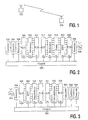
- the system shown in Figure 1 comprises two stations 102, 104, each containing a transceiver, with a two-way radio communication link between them.
- the transmitter shown in Figure 2 processes an input bitstream and broadcasts it using a MCM technique.
- the input bitstream comprises the data to be transmitted, and may optionally have had an error correction code applied to it for enhanced robustness.
- This bitstream is first presented to a converter 202, which generates the required stream of input symbols for further processing.
- a control block 228 ensures that the input symbols generated are appropriate to the modulation scheme being used for transmission, for example 2 bit symbols if Quadrature Phase Shift Keying (QPSK) is to be used.
- QPSK Quadrature Phase Shift Keying
- the control block may also add information to the data stream detailing how diversity has been applied.
- a symbol repeater 204 takes this stream of input symbols and outputs each symbol one or more times, under instruction from the control block 228 (thus giving the possibility of different amounts of diversity for different parts of the data stream). If required, for security reasons, the stream of input symbols may be encrypted by an optional encryption block 206 which, if present, operates under instruction from the control block 228.
- a multiplexer 208 takes as an input a serial stream of N 1 symbols and outputs each symbol onto one of its N 1 parallel output lines.
- the control block 228 may alter the block size so that the stream comprises fewer than N 1 symbols so that fewer output lines are required.
- An interleaver 210 under instruction from the control block 228, reorders the symbols and applies them to its output data lines. These output symbols are then recombined into a serial stream by a demultiplexer 212.
- a multiplexer 214 takes as an input a serial stream of N 2 symbols and outputs each symbol onto one of its N 2 parallel output lines.
- the symbols on each of the output data lines from the multiplexer 214 are then modulated by a modulator 216, where the method of modulation (e.g. QPSK) is controlled by the control block 228 which ensures it is appropriate for the symbols generated by the converter 202. If required, for example in a system serving multiple users at different distances from the transmitter, the power level that will be used to transmit each symbol can be adjusted by an optional power controller block 218.
- the modulated data is then inverse fast Fourier-transformed by an IFFT block 220 before being recombined into a serial data stream by a demultiplexer 222.
- cyclic extension also known as a guard interval
- pulse shaping is performed by a symbol extender block 224, with the aim of avoiding inter-symbol interference.
- the techniques used by the symbol extender block 224 are well known, as described for example in "Principles of Modulation and Channel Coding for Digital Broadcasting for Mobile Receivers" M. Alard and R. Lassalle, EBU Review - Technical, August 1987, pp.168-190.
- a basic task of the control block 228 is to identify the component parts of the input data stream, for example destination information and other control information. This information, together with any information gained about the quality of the transmission channel, enables it to determine the degree of diversity that should be applied to the component parts of the data stream, and to schedule the transmission of data in appropriate time and frequency slots using an appropriate modulation scheme.
- the control block 228 has available up to three adjustable dimensions which can be used to alter the behaviour of the system:
- the choice of modulation scheme for the modulator 216 determines the required size of the input symbol m.
- control block can implement frequency diversity by controlling the algorithm used by the interleaver 210 so that copies of data generated by the repeater 204 appear on different input lines to the IFFT block.
- the receiver shown in Figure 3 receives a broadcast MCM signal and processes it to regenerate the bitstream provided as input to the transmitter.
- a radio reception means 302 generates a complex time domain waveform, from which the cyclic extension added by the transmitter is removed by a symbol recovery block 304.
- the waveform is then supplied as input to a multiplexer 306 which takes a portion of the waveform corresponding to the time taken to transmit one MCM symbol and splits it into N 2 samples, each of which is applied to one of its N 2 parallel output lines.
- a control block 326 can alter the block size so that the waveform is split into fewer than N 2 samples to correspond to the number of carriers actually transmitted.
- the samples are then applied to a FFT block 308 to be fast Fourier-transformed, generating modulated data on each of its output lines.
- the data is demodulated by a symbol demodulator block 310 in which the method of demodulation is controlled by the control block 326 to correspond to that used in transmission.
- the output symbols (which may, of course, be corrupted by transmission errors) are then recombined into a serial stream by a demultiplexer 312.
- a multiplexer 314 takes as input a stream of N 1 symbols and outputs each symbol onto one of its N 1 parallel output lines.
- the control block 326 can alter the block size to correspond to the data block size used for transmission.
- the output symbols are supplied to a de-interleaver 316 which reorders them and applies them to its output lines, under instruction from the control block 326 which uses the same algorithm as on transmission.
- the resultant set of symbols is recombined into a serial stream by a demultiplexer 318.
- the demultiplexer 312 and multiplexer 314 may both be omitted and the output from the demodulator 310 used directly as input to the de-interleaver 316.
- the serial symbol stream is processed by a decryption block 320.
- the combined complex symbol can be determined from where Re(x) provides the real part of x, x i (t) is the received phasor from channel i at time t, x i *(t-1) is the complex conjugate of the received phasor from the previous symbol and g i 2 is a scaling factor chosen to optimise the decision.
- the received data is then determined by comparison of the phase of d(t) with one or more thresholds.
- a converter 324 regenerates the required output bitstream from the stream of symbols passed to it, with the control block 326 ensuring that the conversion is appropriate for the symbols used.
- the first example is for a high bit rate indoor communication system, such as WATM. It is assumed that the channel is stationary or slowly changing and that the input data is protected by channel coding, with codewords long enough to take advantage of the interleaving depth. Time diversity is unlikely to be effective. Parameters for this system are:
- the second example is for a mobile radio system.
- the channel may change rapidly, so that time diversity may be effective.
- the input data to the system consists of coded speech from different users multiplexed into a single data stream.
- coded speech from different users multiplexed into a single data stream.
- For each speech frame errors in some of the bits are less significant from the point of view of speech quality (for example the GSM full rate codec has this property).
- Channel coding is only applied to the most important bits.
- Parameters of the transmission system are:
- This system could, in theory, support about 3300 voice channels.
- the repeater 204 repeats once only the symbols containing coded important bits.
- the total bit rate will be much lower (i.e. speech from one user).
- the input stream may be padded with null data (at least conceptually), in which case the outputs from the modulator 216 will be zero, except for the desired carriers.
- the interleaver 210 would then be configured to produce a small number of symbol blocks (e.g. 2), separated in frequency by a defined spacing. The repeated symbols are placed in different blocks to achieve frequency diversity.
- the speech codec might deliver data in 20ms frames of 100 symbols (200 bits including channel coding). After repetition of the important symbols this would become 160 symbols, which could be transmitted in two groups of 80 symbols. The location of these groups of symbols in the frequency domain could change for successive frames.
- the present invention has a wide range of industrial applicability, including digital audio broadcasting, wireless ATM and future mobile radio systems.
Landscapes
- Engineering & Computer Science (AREA)
- Computer Networks & Wireless Communication (AREA)
- Signal Processing (AREA)
- Quality & Reliability (AREA)
- Radio Transmission System (AREA)
- Detection And Prevention Of Errors In Transmission (AREA)
- Radio Relay Systems (AREA)
- Error Detection And Correction (AREA)
Description
- generating one or more copies of at least some of the symbols;
- reordering the symbols including the copies by applying an interleaving algorithm; and
- varying the interleaving algorithm such that the separation in the frequency domain of the symbols and their respective copies varies with time.
- repetition means for generating one or more copies of least some of the symbols;
- interleaving means for reordering the symbols including the copies by applying an interleaving algorithm; and
- control means for varying the interleaving algorithm such that the separation in the frequency domain of the symbols and their respective copies varies with time.
reception means for receiving a plurality of carriers at different frequencies modulated with symbols;
demodulation means for extracting the symbols from the received carriers;
conversion means for converting the extracted symbols into a bit stream;
characterised by
de-interleaving means for reordering the extracted symbols according to a de-interleaving algorithm;
combining means for generating one output symbol by combining one or more transmitted versions of at least some of the de-interleaved symbols; and
control means for varying the de-interleaving algorithm such that symbols and their respective copies which are separated in the frequency domain by a varying amount are combined by the combining means.

- 1. Under good conditions, with no significant multipath fading, no
diversity is required. Data is transmitted at the gross bit rate (as modified by
channel coding). Interleaving has no benefit so set N1= N2 .
Blocks - 2. Under bad conditions frequency diversity is applied (to all data in this example). In this case all symbols are repeated once. Again set N1= N2 . A fixed block interleaving is applied to separate the repeated symbols by N1/2. In fact, no other re-arrangernent of the symbol ordering is required. The transmission rate is reduced by a factor of two compared with the first mode of operation The order of interleaved symbols could be 1,3,5,...,N1-1,2,4,6,...,N1.
- 3. Under some conditions a fixed diversity separation will not be
effective. An example of such a condition is where the channel transfer function
in the frequency domain is periodic with a period equal to (or a multiple of) the
diversity separation. This condition could occur, for example, where the channel
contains two dominant propagation paths which happen to have a delay
difference equal to the reciprocal of the diversity spacing (or a multiple of the
reciprocal). In this case N1 may be increased, for example to N1= 8 N2. The
interleaver 210 can be configured such that the diversity separations between the repeated symbols are unequal, and change between each of the OFDM symbols. The transmission rate is the same as that for the second mode of operation. The order of the first block of N2 interleaved symbols could be as in the second mode of operation. If a cyclic shift is applied to part of the data the order of the second block could be: 1,3,5,7,9,11,13,15,6,8,10,12,14,16,2,4
Claims (8)
- A method of transmitting data comprising:characterised by:converting a bit stream into symbols;modulating the symbols onto a plurality of carriers of different frequencies; andtransmitting the plurality of carriers;generating one or more copies of at least some of the symbols;reordering the symbols including the copies by applying an interleaving algorithm; andvarying the interleaving algorithm such that the separation in the frequency domain of the symbols and their respective copies varies with time.
- A method as claimed in claim 1, further comprising varying the interleaving algorithm such that the separation in the time domain of the symbols and their respective copies varies with time.
- A method as claimed in claim 1 or 2, further comprising varying the number of data bits per symbols such that the number of carriers transmitted varies with time.
- A transmitter comprising:characterised by:conversion means (202) for converting an input bit stream into symbols modulation means (216) for modulating the symbols onto a plurality of carriers of different frequencies; andtransmission means (226) for transmitting the plurality of carriers;repetition means (204) for generating one or more copies of least some of the symbols;interleaving means (210) for reordering the symbols including the copies by applying an interleaving algorithm; andcontrol means (228) for varying the interleaving algorithm such that the separation in the frequency domain of the symbols and their respective copies varies with time.
- A transmitter as claimed in claim 4, comprising means (228) for varying the interleaving algorithm such that the separation in the time domain of the symbols and their respective copies varies with time.
- A transmitter as claimed in claim 4 or 5, comprising means (228) for varying the number of data bits per symbols such that the number of carriers transmitted varies with time.
- A receiver comprising
reception means (302) for receiving a plurality of carriers at different frequencies modulated with symbols;
demodulation means (310) for extracting the symbols from the received carriers;
conversion means (324) for converting the extracted symbols into a bit stream;
characterised by
de-interleaving means (316) for reordering the extracted symbols according to a de-interleaving algorithm;
combining means (322) for generating one output symbol by combining one or more transmitted versions of at least some of the de-interleaved symbols; and
control means (326) for varying the de-interleaving algorithm such that symbols and their respective copies which are separated in the frequency domain by a varying amount are combined by the combining means. - A receiver as claimed in claim 7, comprising means (326) for varying the de-interleaving algorithm such that symbols and their respective copies which are separated in the time domain by a varying amount are combined by the combining means (322).
Applications Claiming Priority (3)
| Application Number | Priority Date | Filing Date | Title |
|---|---|---|---|
| GB9715396A GB9715396D0 (en) | 1997-07-23 | 1997-07-23 | Radio communication system |
| GB9715396 | 1997-07-23 | ||
| PCT/IB1998/000913 WO1999005798A1 (en) | 1997-07-23 | 1998-06-11 | Radio communication system |
Publications (2)
| Publication Number | Publication Date |
|---|---|
| EP0941585A1 EP0941585A1 (en) | 1999-09-15 |
| EP0941585B1 true EP0941585B1 (en) | 2005-09-28 |
Family
ID=10816231
Family Applications (1)
| Application Number | Title | Priority Date | Filing Date |
|---|---|---|---|
| EP98922999A Expired - Lifetime EP0941585B1 (en) | 1997-07-23 | 1998-06-11 | Radio communication system |
Country Status (7)
| Country | Link |
|---|---|
| EP (1) | EP0941585B1 (en) |
| JP (1) | JP4169796B2 (en) |
| KR (1) | KR100641066B1 (en) |
| DE (1) | DE69831727T2 (en) |
| GB (1) | GB9715396D0 (en) |
| TW (1) | TW374971B (en) |
| WO (1) | WO1999005798A1 (en) |
Families Citing this family (13)
| Publication number | Priority date | Publication date | Assignee | Title |
|---|---|---|---|---|
| WO1999062207A1 (en) * | 1998-05-26 | 1999-12-02 | Jean Armstrong | Data transmission and reception in multicarrier modulation systems |
| US7106689B1 (en) | 1999-03-02 | 2006-09-12 | Matsushita Electric Industrial Co., Ltd. | OFDM transmission/reception apparatus |
| US6278685B1 (en) * | 1999-08-19 | 2001-08-21 | Intellon Corporation | Robust transmission mode |
| AU6478699A (en) | 1999-10-19 | 2001-04-30 | Nokia Networks Oy | Optimising link quality by space and time interleaving |
| KR100364583B1 (en) * | 1999-12-01 | 2002-12-16 | 한국전자통신연구원 | Apparatus and method for repeating and transmitting of memoryless error correction channel coded signal |
| US20020136276A1 (en) * | 2000-03-09 | 2002-09-26 | Franceschini Michael R. | Frequency domain direct sequence spread spectrum with flexible time frequency code |
| EP1263158A1 (en) * | 2001-06-01 | 2002-12-04 | TELEFONAKTIEBOLAGET LM ERICSSON (publ) | Fractional repetition coding |
| US6970519B2 (en) * | 2003-05-29 | 2005-11-29 | Motorola, Inc. | Method and apparatus to enhance audio quality for digitized voice transmitted over a channel employing frequency diversity |
| US7929921B2 (en) | 2003-06-10 | 2011-04-19 | Motorola Mobility, Inc. | Diversity control in wireless communications devices and methods |
| US7418042B2 (en) | 2003-09-17 | 2008-08-26 | Atheros Communications, Inc. | Repetition coding for a wireless system |
| FR2894413A1 (en) * | 2005-12-07 | 2007-06-08 | France Telecom | METHOD AND DEVICE FOR DYNAMIC INTERLACING |
| WO2009009929A1 (en) * | 2007-07-19 | 2009-01-22 | Thomson Licensing | Encryption and decryption methods |
| EP3236604B1 (en) * | 2014-12-17 | 2022-10-26 | Sony Group Corporation | Device and method |
Citations (1)
| Publication number | Priority date | Publication date | Assignee | Title |
|---|---|---|---|---|
| WO1996021293A1 (en) * | 1994-12-30 | 1996-07-11 | France Telecom | Method for the dynamic reconfiguration of a time-interleaved signal, and corresponding receiver and signal |
Family Cites Families (5)
| Publication number | Priority date | Publication date | Assignee | Title |
|---|---|---|---|---|
| US3909721A (en) * | 1972-01-31 | 1975-09-30 | Signatron | Signal processing system |
| US5283780A (en) * | 1990-10-18 | 1994-02-01 | Stanford Telecommunications, Inc. | Digital audio broadcasting system |
| US5305353A (en) * | 1992-05-29 | 1994-04-19 | At&T Bell Laboratories | Method and apparatus for providing time diversity |
| US5761223A (en) * | 1994-07-21 | 1998-06-02 | Matsushita Electric Industrial Co., Ltd. | Error correcting device |
| JP2778498B2 (en) * | 1995-01-11 | 1998-07-23 | 日本電気株式会社 | Spread spectrum diversity transceiver |
-
1997
- 1997-07-23 GB GB9715396A patent/GB9715396D0/en active Pending
-
1998
- 1998-06-11 JP JP50956499A patent/JP4169796B2/en not_active Expired - Lifetime
- 1998-06-11 EP EP98922999A patent/EP0941585B1/en not_active Expired - Lifetime
- 1998-06-11 KR KR1019997002434A patent/KR100641066B1/en not_active Expired - Lifetime
- 1998-06-11 DE DE69831727T patent/DE69831727T2/en not_active Expired - Lifetime
- 1998-06-11 WO PCT/IB1998/000913 patent/WO1999005798A1/en not_active Ceased
- 1998-06-17 TW TW087109665A patent/TW374971B/en active
Patent Citations (1)
| Publication number | Priority date | Publication date | Assignee | Title |
|---|---|---|---|---|
| WO1996021293A1 (en) * | 1994-12-30 | 1996-07-11 | France Telecom | Method for the dynamic reconfiguration of a time-interleaved signal, and corresponding receiver and signal |
Non-Patent Citations (2)
| Title |
|---|
| CIMINI L.: "clustered OFDM with transmitter diversity and coding", GLOBAL TELECOMMUICATION CONFERENCE, vol. 1, 18 November 1996 (1996-11-18) - 22 November 1996 (1996-11-22), LONDON, pages 703 - 707 * |
| TAKAHASHI H.: "ANTENNA AND MULTI CARRIER COMBINED DIVERSITY SYSTEM", IEICE TRANSACTIONS ON COMMUNICATIONS, INSITUTE OF ELECTRONICS INFORMATIONS AND COMM. ENG., vol. E79B, no. 9, 1 September 1996 (1996-09-01), TOKIO, pages 1221 - 1226 * |
Also Published As
| Publication number | Publication date |
|---|---|
| KR20000068608A (en) | 2000-11-25 |
| JP4169796B2 (en) | 2008-10-22 |
| EP0941585A1 (en) | 1999-09-15 |
| DE69831727D1 (en) | 2005-11-03 |
| DE69831727T2 (en) | 2006-06-14 |
| KR100641066B1 (en) | 2006-11-02 |
| GB9715396D0 (en) | 1997-09-24 |
| JP2001501425A (en) | 2001-01-30 |
| WO1999005798A1 (en) | 1999-02-04 |
| TW374971B (en) | 1999-11-21 |
Similar Documents
| Publication | Publication Date | Title |
|---|---|---|
| US11032119B2 (en) | Method and system for combining DFT-transformed OFDM and non-transformed OFDM | |
| US10862609B2 (en) | Methods and systems for OFDM using code division multiplexing | |
| JP4955735B2 (en) | Channel estimation in multi-carrier transmission diversity system | |
| AU2004247167B2 (en) | Apparatus and method for transmitting and receiving a pilot pattern for identification of a base station in an OFDM communication system | |
| KR100520159B1 (en) | Apparatus and method for interference cancellation of ofdm system using multiple antenna | |
| AU2005202543B2 (en) | Apparatus and method for efficiently transmitting broadcasting channel utilizing cyclic delay diversity | |
| CN102984111B (en) | A mobile communication apparatus, a transmitter, a receiver, and transmitting and receiving methods | |
| KR100922980B1 (en) | Channel Estimation Apparatus and Method in Orthogonal Frequency Division Multiplexing System Using Multiple Antennas | |
| KR100584439B1 (en) | Apparatus and Method for Eliminating Interference Signals in Orthogonal Frequency Division Multiplexing System Using Multiple Antennas | |
| EP0941585B1 (en) | Radio communication system | |
| US20120093256A1 (en) | Transmit Diversity Scheme | |
| WO2006106619A1 (en) | Transmitting apparatus, transmitting method, receiving apparatus and receiving method | |
| EP1661346B1 (en) | Apparatus and method for providing a multi-carrier signal to be transmitted and apparatus and method for providing an output signal from a received multi-carrier signal | |
| CN100471191C (en) | Method and device for multi-carrier transmission | |
| JP2003244092A (en) | Multicarrier-CDMA modulation transmission apparatus and multicarrier-CDMA modulation reception apparatus |
Legal Events
| Date | Code | Title | Description |
|---|---|---|---|
| PUAI | Public reference made under article 153(3) epc to a published international application that has entered the european phase |
Free format text: ORIGINAL CODE: 0009012 |
|
| AK | Designated contracting states |
Kind code of ref document: A1 Designated state(s): CH DE FR GB IT LI |
|
| 17P | Request for examination filed |
Effective date: 19990804 |
|
| 17Q | First examination report despatched |
Effective date: 20040902 |
|
| GRAP | Despatch of communication of intention to grant a patent |
Free format text: ORIGINAL CODE: EPIDOSNIGR1 |
|
| GRAS | Grant fee paid |
Free format text: ORIGINAL CODE: EPIDOSNIGR3 |
|
| GRAA | (expected) grant |
Free format text: ORIGINAL CODE: 0009210 |
|
| AK | Designated contracting states |
Kind code of ref document: B1 Designated state(s): CH DE FR GB IT LI |
|
| PG25 | Lapsed in a contracting state [announced via postgrant information from national office to epo] |
Ref country code: LI Free format text: LAPSE BECAUSE OF FAILURE TO SUBMIT A TRANSLATION OF THE DESCRIPTION OR TO PAY THE FEE WITHIN THE PRESCRIBED TIME-LIMIT Effective date: 20050928 Ref country code: CH Free format text: LAPSE BECAUSE OF FAILURE TO SUBMIT A TRANSLATION OF THE DESCRIPTION OR TO PAY THE FEE WITHIN THE PRESCRIBED TIME-LIMIT Effective date: 20050928 |
|
| REG | Reference to a national code |
Ref country code: GB Ref legal event code: FG4D |
|
| REG | Reference to a national code |
Ref country code: CH Ref legal event code: EP |
|
| REF | Corresponds to: |
Ref document number: 69831727 Country of ref document: DE Date of ref document: 20051103 Kind code of ref document: P |
|
| REG | Reference to a national code |
Ref country code: CH Ref legal event code: PL |
|
| ET | Fr: translation filed | ||
| PLBE | No opposition filed within time limit |
Free format text: ORIGINAL CODE: 0009261 |
|
| STAA | Information on the status of an ep patent application or granted ep patent |
Free format text: STATUS: NO OPPOSITION FILED WITHIN TIME LIMIT |
|
| 26N | No opposition filed |
Effective date: 20060629 |
|
| REG | Reference to a national code |
Ref country code: DE Ref legal event code: R082 Ref document number: 69831727 Country of ref document: DE Representative=s name: MEISSNER, BOLTE & PARTNER GBR, DE |
|
| REG | Reference to a national code |
Ref country code: DE Ref legal event code: R082 Ref document number: 69831727 Country of ref document: DE Representative=s name: MEISSNER BOLTE PATENTANWAELTE RECHTSANWAELTE P, DE Effective date: 20140328 Ref country code: DE Ref legal event code: R082 Ref document number: 69831727 Country of ref document: DE Representative=s name: MEISSNER, BOLTE & PARTNER GBR, DE Effective date: 20140328 Ref country code: DE Ref legal event code: R081 Ref document number: 69831727 Country of ref document: DE Owner name: KONINKLIJKE PHILIPS N.V., NL Free format text: FORMER OWNER: KONINKLIJKE PHILIPS ELECTRONICS N.V., EINDHOVEN, NL Effective date: 20140328 |
|
| REG | Reference to a national code |
Ref country code: FR Ref legal event code: CD Owner name: KONINKLIJKE PHILIPS N.V., NL Effective date: 20141126 Ref country code: FR Ref legal event code: CA Effective date: 20141126 |
|
| REG | Reference to a national code |
Ref country code: FR Ref legal event code: PLFP Year of fee payment: 19 |
|
| REG | Reference to a national code |
Ref country code: FR Ref legal event code: PLFP Year of fee payment: 20 |
|
| PGFP | Annual fee paid to national office [announced via postgrant information from national office to epo] |
Ref country code: FR Payment date: 20170629 Year of fee payment: 20 Ref country code: GB Payment date: 20170630 Year of fee payment: 20 |
|
| PGFP | Annual fee paid to national office [announced via postgrant information from national office to epo] |
Ref country code: IT Payment date: 20170623 Year of fee payment: 20 |
|
| PGFP | Annual fee paid to national office [announced via postgrant information from national office to epo] |
Ref country code: DE Payment date: 20170831 Year of fee payment: 20 |
|
| REG | Reference to a national code |
Ref country code: DE Ref legal event code: R071 Ref document number: 69831727 Country of ref document: DE |
|
| REG | Reference to a national code |
Ref country code: GB Ref legal event code: PE20 Expiry date: 20180610 |
|
| PG25 | Lapsed in a contracting state [announced via postgrant information from national office to epo] |
Ref country code: GB Free format text: LAPSE BECAUSE OF EXPIRATION OF PROTECTION Effective date: 20180610 |