EP0941490B1 - Deflektor - Google Patents
Deflektor Download PDFInfo
- Publication number
- EP0941490B1 EP0941490B1 EP97911524A EP97911524A EP0941490B1 EP 0941490 B1 EP0941490 B1 EP 0941490B1 EP 97911524 A EP97911524 A EP 97911524A EP 97911524 A EP97911524 A EP 97911524A EP 0941490 B1 EP0941490 B1 EP 0941490B1
- Authority
- EP
- European Patent Office
- Prior art keywords
- deflector
- vessel
- wings
- deflector according
- wing
- Prior art date
- Legal status (The legal status is an assumption and is not a legal conclusion. Google has not performed a legal analysis and makes no representation as to the accuracy of the status listed.)
- Expired - Lifetime
Links
- XLYOFNOQVPJJNP-UHFFFAOYSA-N water Substances O XLYOFNOQVPJJNP-UHFFFAOYSA-N 0.000 claims description 2
- 230000008878 coupling Effects 0.000 description 4
- 238000010168 coupling process Methods 0.000 description 4
- 238000005859 coupling reaction Methods 0.000 description 4
- 230000000694 effects Effects 0.000 description 4
- 238000010276 construction Methods 0.000 description 1
- 238000012423 maintenance Methods 0.000 description 1
- 238000005259 measurement Methods 0.000 description 1
- 230000007246 mechanism Effects 0.000 description 1
- 230000009467 reduction Effects 0.000 description 1
- 230000002787 reinforcement Effects 0.000 description 1
- 230000008439 repair process Effects 0.000 description 1
Images

Classifications
-
- B—PERFORMING OPERATIONS; TRANSPORTING
- B63—SHIPS OR OTHER WATERBORNE VESSELS; RELATED EQUIPMENT
- B63B—SHIPS OR OTHER WATERBORNE VESSELS; EQUIPMENT FOR SHIPPING
- B63B21/00—Tying-up; Shifting, towing, or pushing equipment; Anchoring
- B63B21/56—Towing or pushing equipment
- B63B21/66—Equipment specially adapted for towing underwater objects or vessels, e.g. fairings for tow-cables
Definitions
- This invention relates to a deflector for towing after a vessel, especially for use in seismic surveys at sea, being adapted to pull equipment to a transversal position in relation to the vessels moving direction, comprising at least one connecting point for coupling, through wires or similar, to the vessel and the equipment to be towed, and two or more deflector wings adapted to provide a lifting force transversally in relation to the direction of the vessels movement.
- Such deflectors are traditionally passive devices comprising one or more wings providing a lift in the required direction. Because of the towing resistance in the water, caused both by the deflector and the towed cables, there are, however, limits to the lift which may be obtained using passive deflectors, which in turn, together with a wish in seismic studies to keep the seismic cables as close to the vessel as possible, limits how far the deflectors may be pulled transversally. When the deflector is used in seismic surveys it will in addition be loaded with the seismic cable to be pulled sideways. Today there is a limit to the width of the cable tow with passive deflectors being approximately 800 metres, with approximately 10 seismic cables.
- the invention provides an active deflector which, depending on its dimensions, may double the width of the seismic survey, and thus halve the number of passes of the vessel over the area to be surveyed.
- the deflector according to the invention may be used in surveys with ordinary widths, where the dimensions are reduced, so that the towing resistance from the system is reduced. Because of the shape of the cylinder it will not affect the passive lifting capability of the deflector significantly, so that the seismic cables are kept at a certain distance from each other even if the power supply fails, and damages on the seismic cables are reduced.
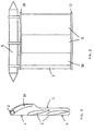
- FIG 1 a section of a deflector according to the invention is shown comprising the three wings 3,3a and a rotating cylinder 2 in the front of the foremost wing 3a.
- the deflector also comprises two connecting points 4 for coupling to the towing vessel 7, and to the towed equipment 2.
- rotating cylinder 2 is, in the figure, positioned in front of the foremost wing, which is the position providing the greatest effect in the illustrated example.
- Rotating cylinders may also be mounted in the other wings to improve the lift even further.
- the cylinder described here may, however be shaped in different ways, with a constant diameter along their complete axis or with a varying diameter preferably adapted to the shape of the associated wing.
- the wing and the cylinder are preferably adapted to each other so that they together constitute a deflector wing having a certain lift when the cylinder is not activated.
- the cylinder may be driven in different ways, e.g. using hydraulic or electrical engines (not shown).
- the rotational velocity of the cylinder may be controlled in a simple way to adjust the lift of the deflector.
- Figure 2 shows the deflector as seen from one side, being equipped with plates 10,11 on the upper and lower sides connecting the wings 3a,3 to each other, and also a container 5 on the upper side.
- the container 5 may contain different control mechanisms, drive units for the cylinder(s) and, in some cases, power supplies for the cylinder(s). It may also comprise a buoyancy tank for keeping the deflector in a required position in relation to the surface. The latter may also be obtained using additional wings (not shown) being capable of steering the deflector to a certain depth.
- the support vessel 9 may provide electrical or hydraulic power through the cable, in addition to control signals or the like for controlling the deflector. Also the support vessel may provide a certain towing force which may contribute in increasing the distance, perpendicular to the moving direction, between the towing vessel and the deflector.
- the support vessel 9 may preferably be remote controlled so that the position relative to the towing vessel is controlled continuously. In the same way the positions of the deflectors in relation to the towing vessel may be remote controlled via the support vessel and a cable 6 stretching from the support vessel 9 to the deflector 1.
- the support vessel should, however, be manned to be able to provide maintenance and repairs on board regardless of weather conditions. In seismic surveys the support vessels may also be equipped with seismic sources or receivers to contribute to the data acquisition in the survey.
- FIG 3 also shows a number of seismic cables, comprising seismic receivers and/or sources, being towed behind the towing vessel.
- the width of such as search may be up to 800 metres with 10 cables.
- this width may be increased to 2000 metres, with 18 cables 8. This means considerable reductions in expenses, which allows for the use of the support vessels.
- the deflectors characteristics as a passive deflector avoids a total collapse of the spread of the search, so that the cables do not come close to each other and damaged, and the seismic survey in some cases may be continued, but to a limited extent.
- the construction of the couplings between the towing wires, power supplies, deflectors and vessels may comprise any solution and are not relevant to this invention.
Landscapes
- Chemical & Material Sciences (AREA)
- Engineering & Computer Science (AREA)
- Combustion & Propulsion (AREA)
- Mechanical Engineering (AREA)
- Ocean & Marine Engineering (AREA)
- Geophysics And Detection Of Objects (AREA)
Claims (9)
- Ablenker zum Schleppen hinter einem Schiff, insbesondere für Verwendung in Bezug auf seismische Untersuchungen, der dazu ausgebildet ist, Ausrüstung zu einer Transversalstellung in Bezug auf die Bewegungsrichtung des Schiffes zu ziehen, der wenigstens einen Verbindungspunkt (4) zum Verbinden mit dem Schiff (7) und der zu schleppenden Ausrüstung (8) durch Drähte (12) oder ähnliches aufweist,
gekennzeichnet durch zwei oder mehr Ablenkerflügel (3, 3a), die dazu ausgebildet sind, den Ablenker (1) mit einer Hebe- oder Auftriebskraft quer in Bezug auf die Bewegungsrichtung des Schiffes zu versehen, wobei wenigstens einer der Flügel (3, 3a) mit einem rotierenden Zylinder versehen ist, der vor dem Flügel angeordnet ist, um den Auftrieb des Ablenkerflügels zu erhöhen, und durch einen Antriebseinheit zum Antreiben des rotierenden Zylinders mit entsprechenden Einrichtungen für die Energieversorgung. - Ablenker nach Anspruch 1, dadurch gekennzeichnet, daß der Ablenker drei Flügel (3, 3a) aufweist und daß der vorderste Ablenkerflügel (3a) mit einem rotierenden Zylinder (2) an seiner Vorderseite versehen ist.
- Ablenker nach Anspruch 1 oder 2, dadurch gekennzeichnet, daß einer oder mehrere rotierende Zylinder (2) durch einen oder mehrere Elektromotoren angetrieben sind.
- Ablenker nach Anspruch 1 oder 2, dadurch gekennzeichnet, daß ein oder mehrere rotierende Zylinder (2) durch eine oder mehrere hydraulische Antriebseinheiten, vorzugsweise wasserhydraulische, angetrieben wird/werden.
- Ablenker nach einem der vorangehenden Ansprüche, dadurch gekennzeichnet, daß die Ablenkerflügel (3, 3a) durch mindestens eine Befestigungseinrichtung (10) miteinander verbunden sind und daß die obere Befestigungseinrichtung mit Antriebseinheiten (5) für den (die) rotierenden Zylinder (2) versehen ist.
- Ablenker nach Anspruch 5, dadurch gekennzeichnet, daß die obere Befestigungseinrichtung (10) Auftriebs- und Steuereinheiten (5) einschließt.
- Ablenker nach einem der vorangehenden Ansprüche, dadurch gekennzeichnet, daß er Verbindungsmittel (4) zum Verbinden mit einem Hilfsschiff (9) aufweist, das dazu ausgebildet ist, den Ablenker (1) parallel zur Richtung der Bewegung zu ziehen.
- Ablenker nach einem der vorangehenden Ansprüche, dadurch gekennzeichnet, daß die Energieversorgung elektrische oder hydraulische Kabel aufweist, die an ihren gegenüberliegenden Enden mit einem Hilfsschiff (9) verbunden sind, das dazu ausgebildet ist, den Ablenker mit Energie zu versorgen.
- Ablenker nach Anspruch 7 oder 8, dadurch gekennzeichnet, daß das Hilfsschiff (9) mit dem Ablenker durch einen Schleppdraht (12) oder ähnliches verbunden ist, das sich vom ersten Schiff zum Ablenker erstreckt.
Applications Claiming Priority (3)
| Application Number | Priority Date | Filing Date | Title |
|---|---|---|---|
| NO965214 | 1996-12-06 | ||
| NO965214A NO305674B1 (no) | 1996-12-06 | 1996-12-06 | Deflektor med justerbar vinge for seismisk slep |
| PCT/NO1997/000302 WO1998025162A1 (en) | 1996-12-06 | 1997-11-14 | Deflector |
Publications (2)
| Publication Number | Publication Date |
|---|---|
| EP0941490A1 EP0941490A1 (de) | 1999-09-15 |
| EP0941490B1 true EP0941490B1 (de) | 2002-05-08 |
Family
ID=19900149
Family Applications (1)
| Application Number | Title | Priority Date | Filing Date |
|---|---|---|---|
| EP97911524A Expired - Lifetime EP0941490B1 (de) | 1996-12-06 | 1997-11-14 | Deflektor |
Country Status (5)
| Country | Link |
|---|---|
| EP (1) | EP0941490B1 (de) |
| AU (1) | AU4887797A (de) |
| DE (1) | DE69712513D1 (de) |
| NO (1) | NO305674B1 (de) |
| WO (1) | WO1998025162A1 (de) |
Families Citing this family (11)
| Publication number | Priority date | Publication date | Assignee | Title |
|---|---|---|---|---|
| ES2193372T3 (es) * | 1996-04-30 | 2003-11-01 | Helgi Larsen | Panel de red. |
| AU2001287988B2 (en) * | 2000-09-28 | 2005-08-11 | Westerngeco As | Deflector devices |
| WO2002030736A1 (en) * | 2000-09-28 | 2002-04-18 | Westerngeco As | Deflector devices |
| US6532189B2 (en) * | 2000-11-30 | 2003-03-11 | Westerngeco L.L.C. | Curved float for marine divertors |
| NO321016B1 (no) | 2001-01-24 | 2006-02-27 | Petroleum Geo Services As | System for styring av kabler i et seismisk slep og hvor noen av kablene har kontrollenheter innrettet for a male og rapportere om sine posisjoner |
| NO20035477L (no) * | 2003-12-09 | 2005-06-10 | Henning Skjold Larsen | Drivanordninger, justeringsanordninger og system i forbindelse med en tral samt fremgangsmate for traling og styringssystem for bruk i fremgangsmaten |
| US7404370B2 (en) * | 2006-08-02 | 2008-07-29 | Pgs Norway Geophysical As | Steerable diverter for towed seismic streamer arrays |
| US20100126057A1 (en) * | 2007-07-31 | 2010-05-27 | Sherif Adham Safwat | High stability, high efficiency trawl door and methods |
| US7881153B2 (en) | 2007-08-21 | 2011-02-01 | Pgs Geophysical As | Steerable paravane system for towed seismic streamer arrays |
| US8267031B2 (en) | 2010-02-24 | 2012-09-18 | Pgs Geophysical As | Tension management control system and methods used with towed marine sensor arrays |
| US9664811B2 (en) | 2012-12-19 | 2017-05-30 | Pgs Geophysical As | Methods and systems for using a combined electromagnetic source electrode and deflector |
Family Cites Families (4)
| Publication number | Priority date | Publication date | Assignee | Title |
|---|---|---|---|---|
| US4630997A (en) * | 1981-11-24 | 1986-12-23 | Fondation Cousteau | Apparatus for producing a force when in a moving fluid |
| US4729333A (en) * | 1986-07-09 | 1988-03-08 | Exxon Production Research Company | Remotely-controllable paravane |
| EP0562780B1 (de) * | 1992-03-24 | 1996-05-08 | Geco A.S. | Ottergerät |
| GB2293806A (en) * | 1994-09-10 | 1996-04-10 | Edwin Ashworth Marine Ltd | Cable separator. |
-
1996
- 1996-12-06 NO NO965214A patent/NO305674B1/no not_active IP Right Cessation
-
1997
- 1997-11-14 WO PCT/NO1997/000302 patent/WO1998025162A1/en not_active Ceased
- 1997-11-14 AU AU48877/97A patent/AU4887797A/en not_active Abandoned
- 1997-11-14 EP EP97911524A patent/EP0941490B1/de not_active Expired - Lifetime
- 1997-11-14 DE DE69712513T patent/DE69712513D1/de not_active Expired - Lifetime
Also Published As
| Publication number | Publication date |
|---|---|
| WO1998025162A1 (en) | 1998-06-11 |
| DE69712513D1 (de) | 2002-06-13 |
| EP0941490A1 (de) | 1999-09-15 |
| NO965214L (no) | 1998-06-08 |
| NO965214D0 (no) | 1996-12-06 |
| NO305674B1 (no) | 1999-07-05 |
| AU4887797A (en) | 1998-06-29 |
Similar Documents
| Publication | Publication Date | Title |
|---|---|---|
| US6234102B1 (en) | Deflector | |
| EP0941199B1 (de) | Schleppsystem für material auf see | |
| US7577060B2 (en) | Systems and methods for steering seismic arrays | |
| EP0941490B1 (de) | Deflektor | |
| US7738317B2 (en) | Apparatus and methods for controlling position of marine seismic sources | |
| GB2400662A (en) | Positioning system for seismic array | |
| AU2002222363B2 (en) | Deflector devices | |
| EP2583123A1 (de) | Seismisches unterwassermesssystem und verfahren zur aktiven lenkung von source-arrays in solch einem system | |
| AU2002222363A1 (en) | Deflector devices | |
| US4748599A (en) | Control device for cables with seismic equipment, especially for gun cables comprising one or several gun arrays | |
| US7156035B2 (en) | Deflector devices | |
| AU2001287988A1 (en) | Deflector devices | |
| AU2002222362B2 (en) | Deflector devices | |
| US7469652B2 (en) | Deflector devices | |
| DK202070679A1 (en) | Marine seismic acquisition with a support vessel | |
| NO20191059A1 (en) | Bridle block for a deflector | |
| US11874422B2 (en) | Steering of marine equipment towed by a vessel by a running block | |
| WO2018080311A1 (en) | A bridle for a marine deflector | |
| BRPI0410208B1 (pt) | Produto alimentício de emulsão óleo-em-água que pode ser batido, e, confeito batido que pode ser preparado e exibido em temperaturas ambientes | |
| BRPI0409555B1 (pt) | Método para posicionar um arranjo de fontes rebocado atras de um navio e sistema para pesquisa sísmica para uso em água |
Legal Events
| Date | Code | Title | Description |
|---|---|---|---|
| PUAI | Public reference made under article 153(3) epc to a published international application that has entered the european phase |
Free format text: ORIGINAL CODE: 0009012 |
|
| 17P | Request for examination filed |
Effective date: 19990628 |
|
| AK | Designated contracting states |
Kind code of ref document: A1 Designated state(s): BE DE DK ES FI FR GB GR IE IT NL PT SE |
|
| RIN1 | Information on inventor provided before grant (corrected) |
Inventor name: GODOY, ERIK Inventor name: RUSSELL, MICHAEL, JOHN |
|
| GRAG | Despatch of communication of intention to grant |
Free format text: ORIGINAL CODE: EPIDOS AGRA |
|
| 17Q | First examination report despatched |
Effective date: 20010705 |
|
| GRAG | Despatch of communication of intention to grant |
Free format text: ORIGINAL CODE: EPIDOS AGRA |
|
| GRAH | Despatch of communication of intention to grant a patent |
Free format text: ORIGINAL CODE: EPIDOS IGRA |
|
| REG | Reference to a national code |
Ref country code: GB Ref legal event code: IF02 |
|
| GRAH | Despatch of communication of intention to grant a patent |
Free format text: ORIGINAL CODE: EPIDOS IGRA |
|
| GRAA | (expected) grant |
Free format text: ORIGINAL CODE: 0009210 |
|
| AK | Designated contracting states |
Kind code of ref document: B1 Designated state(s): BE DE DK ES FI FR GB GR IE IT NL PT SE |
|
| PG25 | Lapsed in a contracting state [announced via postgrant information from national office to epo] |
Ref country code: NL Free format text: LAPSE BECAUSE OF FAILURE TO SUBMIT A TRANSLATION OF THE DESCRIPTION OR TO PAY THE FEE WITHIN THE PRESCRIBED TIME-LIMIT Effective date: 20020508 Ref country code: IT Free format text: LAPSE BECAUSE OF FAILURE TO SUBMIT A TRANSLATION OF THE DESCRIPTION OR TO PAY THE FEE WITHIN THE PRESCRIBED TIME-LIMIT;WARNING: LAPSES OF ITALIAN PATENTS WITH EFFECTIVE DATE BEFORE 2007 MAY HAVE OCCURRED AT ANY TIME BEFORE 2007. THE CORRECT EFFECTIVE DATE MAY BE DIFFERENT FROM THE ONE RECORDED. Effective date: 20020508 Ref country code: GR Free format text: LAPSE BECAUSE OF FAILURE TO SUBMIT A TRANSLATION OF THE DESCRIPTION OR TO PAY THE FEE WITHIN THE PRESCRIBED TIME-LIMIT Effective date: 20020508 Ref country code: FR Free format text: LAPSE BECAUSE OF FAILURE TO SUBMIT A TRANSLATION OF THE DESCRIPTION OR TO PAY THE FEE WITHIN THE PRESCRIBED TIME-LIMIT Effective date: 20020508 Ref country code: FI Free format text: LAPSE BECAUSE OF FAILURE TO SUBMIT A TRANSLATION OF THE DESCRIPTION OR TO PAY THE FEE WITHIN THE PRESCRIBED TIME-LIMIT Effective date: 20020508 Ref country code: BE Free format text: LAPSE BECAUSE OF FAILURE TO SUBMIT A TRANSLATION OF THE DESCRIPTION OR TO PAY THE FEE WITHIN THE PRESCRIBED TIME-LIMIT Effective date: 20020508 |
|
| REG | Reference to a national code |
Ref country code: IE Ref legal event code: FG4D |
|
| REF | Corresponds to: |
Ref document number: 69712513 Country of ref document: DE Date of ref document: 20020613 |
|
| PG25 | Lapsed in a contracting state [announced via postgrant information from national office to epo] |
Ref country code: SE Free format text: LAPSE BECAUSE OF FAILURE TO SUBMIT A TRANSLATION OF THE DESCRIPTION OR TO PAY THE FEE WITHIN THE PRESCRIBED TIME-LIMIT Effective date: 20020808 Ref country code: PT Free format text: LAPSE BECAUSE OF FAILURE TO SUBMIT A TRANSLATION OF THE DESCRIPTION OR TO PAY THE FEE WITHIN THE PRESCRIBED TIME-LIMIT Effective date: 20020808 Ref country code: DK Free format text: LAPSE BECAUSE OF FAILURE TO SUBMIT A TRANSLATION OF THE DESCRIPTION OR TO PAY THE FEE WITHIN THE PRESCRIBED TIME-LIMIT Effective date: 20020808 |
|
| PG25 | Lapsed in a contracting state [announced via postgrant information from national office to epo] |
Ref country code: DE Free format text: LAPSE BECAUSE OF FAILURE TO SUBMIT A TRANSLATION OF THE DESCRIPTION OR TO PAY THE FEE WITHIN THE PRESCRIBED TIME-LIMIT Effective date: 20020809 |
|
| NLV1 | Nl: lapsed or annulled due to failure to fulfill the requirements of art. 29p and 29m of the patents act | ||
| PG25 | Lapsed in a contracting state [announced via postgrant information from national office to epo] |
Ref country code: IE Free format text: LAPSE BECAUSE OF NON-PAYMENT OF DUE FEES Effective date: 20021114 |
|
| PG25 | Lapsed in a contracting state [announced via postgrant information from national office to epo] |
Ref country code: ES Free format text: LAPSE BECAUSE OF FAILURE TO SUBMIT A TRANSLATION OF THE DESCRIPTION OR TO PAY THE FEE WITHIN THE PRESCRIBED TIME-LIMIT Effective date: 20021128 |
|
| EN | Fr: translation not filed | ||
| PLBE | No opposition filed within time limit |
Free format text: ORIGINAL CODE: 0009261 |
|
| STAA | Information on the status of an ep patent application or granted ep patent |
Free format text: STATUS: NO OPPOSITION FILED WITHIN TIME LIMIT |
|
| 26N | No opposition filed |
Effective date: 20030211 |
|
| REG | Reference to a national code |
Ref country code: IE Ref legal event code: MM4A |
|
| PGFP | Annual fee paid to national office [announced via postgrant information from national office to epo] |
Ref country code: GB Payment date: 20161128 Year of fee payment: 20 |
|
| REG | Reference to a national code |
Ref country code: GB Ref legal event code: PE20 Expiry date: 20171113 |
|
| PG25 | Lapsed in a contracting state [announced via postgrant information from national office to epo] |
Ref country code: GB Free format text: LAPSE BECAUSE OF EXPIRATION OF PROTECTION Effective date: 20171113 |