BACKGROUND OF THE INVENTION
1. Field of the Invention
The present invention relates to a photoresist film and
a method for formation of a pattern for the photoresist film.
2. Description of the Related Art
Large-scale integrated semiconductor circuits
(hereafter referred to as "LSIs") are becoming more and more
highly integrated in recent years, requiring scale reduction
to a size smaller than the design rule. As a light source to
be used in a photolithography step, a mercury lamp (i-beam;
365 nm) or a KrF excimer laser (248 nm) is becoming prevalent.
However, a design rule to be expected in the future (0.2 µ
m or less) requires formation of a pattern of a size less than
the wavelengths of these light sources, so that a new method
must be developed.
An approach to this demand using a mono-layer resist film
is now being studied along the following line. Namely, a method
of using the deformation radiation or phase shift method in
combination with the KrF excimer laser is now studied as the
first method. This method achieves a resolution of 0.14 µ
m with a film thickness of 1000 Å. Also, a method of adopting
an ArF excimer laser (193 nm) as a new light source is now being
studied as the second method. The ArF excimer laser achieves
a resolution of 0.12 µm with a film thickness of 1000 Å. For
use in the future, a method of using the deformation radiation
or phase shift method in combination with the ArF excimer laser
is studied as the third method. This method achieves a
resolution of 0.1 µm with a film thickness of 1000 Å.
When these methods are used, it is possible to form a very
fine pattern with a resolution of 0.15 µm or less if the film
thickness is not considered. Actually, however, an etching
step must be carried out after the photoresist film is patterned,
so that the thickness of the photoresist film must be at least
5000 Å. The resolution for this film thickness of 5000 Å is
0.18 µm by the first method, 0.16 µm by the second method,
and 0.14 µm by the third method. Therefore, according as the
thickness of the photoresist film increases, the resolution
becomes worse than the original resolution (achieved by the
thickness of 1000 Å) by about 0.04 µm. In other words, as long
as a pattern is formed using a conventional mono-layer
photoresist film, the thickness of the photoresist film is
determined by taking account of the resistance to etching in
the next step, so that the advantage of fine resolution is not
sufficiently drawn out yet.
On the other hand, a patterning method known as the surface
modification method is studied, in which the surface of a
photoresist film is silylated after the exposure to light, and
then a dry development is carried out to form a pattern having
a high resolution and excellent resistance to dry etching.
According to this technique, an initial pattern is formed in
a region of about 1000 Å thickness within the surface of the
photoresist film, so that the resolution is higher than the
one achieved by the conventional methods. Also, since the
silylated layer formed in the surface can firmly protect the
lower layer, the pattern can be made to have an excellent
resistance to dry etching. However, at the dry development
step, a plasma cuts a sidewall of the photoresist layer under
the silylated layer, thereby forming a tapered cross section.
Also, because of an inherent property that the formation of
the silylated surface proceeds by diffusion within the
substance, the stability of the pattern dimension is poor, so
that the method is hardly practicable.
Accordingly, a patterning method using a multi-layer
photoresist is now being developed. For example, in a method
disclosed in Japanese Unexamined Patent Publication No. Hei
7(1995)-142365, a lower resist layer 43 which is sensitive to
the i-beam is formed on a film 42 to be etched in a later step,
and an upper resist layer 44 which is sensitive to the KrF
excimer laser beam is mounted on the lower resist layer 43 (Fig.
5(a)). Subsequently, a KrF excimer laser beam is applied using
a mask, followed by development to pattern only the upper resist
layer 44 (Fig. 5(b)). Then, the i-beam is applied over an
entire surface, followed by development. However, although
a pattern can be formed in principle by this method, the applied
beam cannot be completely shielded by the upper resist layer
44 at the second exposure step using the i-beam, so that as
a result the lower resist layer 43 as a whole is exposed to
the i-beam, thus making a line width of the lower resist layer
43 non-uniform and making it difficult to form a good pattern,
as shown in Fig. 5(c). Here, in Figs. 5(a) to 5(c), the
reference numeral 41 represents a wafer substrate.
Therefore, at present, a photoresist film that overcomes
the problem of decrease in the resolution due to the thickness
of the photoresist film has not been developed yet.
SUMMARY OF THE INVENTION
The present invention has been made in view of these
circumstances and the purpose thereof is to provide a
photoresist film that can be patterned without causing decrease
in the resolution due to the thickness of the photoresist film
and without deteriorating the resistance to dry etching in
forming a pattern using an exposure light such as a KrF or ArF
excimer laser beam, and a method for forming a pattern therefor.
Accordingly, the present invention provides a photoresist
film comprising a three-layer structure of a lower layer, a
middle layer and an upper layer, wherein the lower and upper
layers are photoresist layers, the lower layer is sensitive
to a light having a longer wavelength than a light to which
the upper layer is sensitive, and the middle layer is a
light-shielding film formed of an organic substance that has
a transmittance such that the lower layer is not exposed to
lights to which the lower and upper layers are sensitive.
Also, the present invention provides a method of forming
a pattern of a photoresist film comprising the steps of: forming
the photoresist film of these layer structure as mentioned
above on a layer to be etched; patterning only the upper layer
by applying a light to which the upper layer is sensitive, using
a mask of a predetermined shape; etching the middle layer which
has been exposed at the patterning step, until a surface of
the lower layer is exposed; and applying a light to which the
lower layer is sensitive, over an entire surface to pattern
the lower layer.
BRIEF DESCRIPTION OF THE DRAWINGS
The present invention will be better understood from the
following detailed description of preferred embodiments of the
invention, taken in conjunction with the accompanying drawings,
in which:
DETAILED DESCRIPTION OF THE PREFERRED EMBODIMENTS
The present invention will be detailed by way of Examples
shown below. However, these Examples are not intended to limit
the scope of the present invention.
Fig. 1 is a view showing a state in which a photoresist
film of the present invention is formed on a layer to be etched;
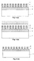
and Figs. 2(a) to 4(c) are cross-sectional views each showing
a part of the steps for forming a pattern of the photoresist
film of the present invention. In Figs. 1 to 4(c), a wafer
substrate 1, a film 2 to be etched, a lower layer 3, a middle
layer 4, an upper layer 5, and a mask 6 are shown.
The layer to be etched is a layer on which a pattern in
a desired configuration is to be formed by photolithography
and etching. This layer is typically formed on a semiconductor
substrate directly or with intervention of one or more of a
device such as a transistor or a capacitor, an insulating film,
a conductive layer and the like, but may be a semiconductor
substrate itself. The layer to be etched may be formed of a
metal such as aluminum, copper, silver, gold or platinum, a
high-melting point metal such as tungsten, tantalum, cobalt
or titanium, an alloy containing such a metal, a polysilicon,
a silicide or polycide composed of polysilicon and such a metal,
or the like. The thickness of the layer is not particularly
limited.
First, referring to Fig. 1, the photoresist film of the
present invention has a three-layer structure of the lower
layer 3, the middle layer 4 and the upper layer 5. The lower
layer 3 is a photoresist layer that is sensitive to an i-beam
or a KrF excimer laser beam. The middle layer 4 is a
light-shielding film formed of an organic substance that has
a transmittance such that the lower layer is not exposed to
lights to which the lower and upper layers are sensitive. The
upper layer 5 is a photoresist layer that is sensitive to a
KrF excimer laser beam or an ArF excimer laser beam. Here,
the transmittance is preferably 50% or less. Here, although
the lights to which the lower and upper layer are sensitive
are specifically shown in this specification, they are merely
for exemplifying purposes and the lights to be used are not
specifically limited as long as the wavelength of the light
to which the lower layer is sensitive is longer than the
wavelength of the light to which the upper layer is sensitive.
The middle layer 4 is preferably formed of an organic
substance from the view points of the facility in forming, the
damages to the lower layer and the resistance to dry etching.
If the middle layer 4 is formed of an inorganic substance,
control of the film thickness is difficult, the lower layer
is liable to be damaged at the time of forming the middle film
4, and moreover the etching rate is slow with respect to the
resistance to dry etching, so that inorganic substances are
not suitable as the material for the middle layer of the
photoresist film of the present invention.
A method for forming a pattern of the photoresist film
of the present invention will now be explained. First, the
photoresist film is formed on the film 2 to be etched, as shown
in Fig. 2(a). Then, the upper layer 5 of the photoresist film
is exposed to a KrF excimer laser beam or an ArF excimer laser
beam (hereafter referred to as "first exposure") by means of
the mask 6 (Fig. 2(b)), followed by development to pattern only
the upper layer 5 (hereafter referred to as "first patterning")
(Fig. 2(c)). Thus, only the upper layer 5 is patterned to
separate the upper layer 5 into a portion where the upper layer
5 is removed to expose the underlying middle layer 4 to ambient
atmosphere and a portion where the upper layer 5 remains as
it is. At this stage, the lower layer 3 and the middle layer
4 are not patterned at all.
Therefore, the upper layer 5 of the photoresist film of
the present invention is preferably made of a photoresist layer
that is sensitive to the KrF excimer laser beam or the ArF
excimer laser beam. This resist may be either a positive type
or a negative type. On the contrary, the middle layer 4 must
shield the light so that the lower layer 3 is not exposed to
the light at the first exposure step.
Next, the entire surface is subjected to an etching
treatment by means of an oxygen plasma generating apparatus
(Fig. 3(a)). The etching treatment is carried out to such a
degree that the middle layer 4 exposed to ambient atmosphere
after the first patterning step is completely removed whereas
the middle layer 4 under the remaining portion of the upper
layer 5 is not completely removed (Fig. 3(b)). Hereafter, the
etching treatment under this condition is referred to as "half
etching".
Subsequently, the entire surface is exposed to the i-beam
or the KrF excimer laser beam (hereafter referred to as
"second exposure") without using a mask (Fig. 3(c)), followed
by development to pattern the lower layer 3 (hereafter referred
to as "second patterning") (Fig. 4(a)). At the second exposure
step, the lower layer 3 under the middle layer 4 is not exposed
to the light because the light is shielded by the portion of
the upper layer 5 remaining after the first patterning step,
i.e. by the portion of the middle layer 4 remaining after the
half etching step.
On the other hand, the lower layer 3 is exposed to the
light by the second exposure at the portion of the middle layer
4 which is exposed to ambient atmosphere after the first
patterning, i.e. at the portion of the lower layer 3 which is
exposed to ambient atmosphere by complete removal of the middle
layer 4 after the half etching step (the exposed portion of
the lower layer 3 appearing after the half etching step).
Therefore, the middle layer 4 of the photoresist film of the
present invention must shield the lights (radiated beams) both
at the first and second exposure steps. In other words, if
the first exposure uses the KrF excimer laser beam and the
second exposure uses the i-beam, the transmittance of the
middle layer 4 to each one of the i-beam and the KrF excimer
laser beam is preferably 50% or less. If the first exposure
uses the ArF excimer laser beam and the second exposure uses
the KrF excimer laser beam, the transmittance of the middle
layer 4 to each one of the ArF excimer laser beam and the KrF
excimer laser beam is preferably 50% or less. If the first
exposure uses the ArF excimer laser beam and the second exposure
uses the i-beam, the transmittance of the middle layer 4 to
each one of the i-beam and the ArF excimer laser beam is
preferably 50% or less.
Also, the lower layer 3 of the photoresist film of the
present invention is preferably made of a photoresist layer
which is sensitive to the KrF excimer laser beam or the i-beam.
After the photoresist pattern is formed (Fig. 4(b)),
ordinary LSI manufacturing steps are carried out to etch the
film 2 formed on the wafer substrate 1 (Fig. 4(c)). The
resistance to etching after the final patterning step of the
present invention is borne by all of the remaining three-layers.
Further, even after the etching step is ended, the lower layer
3 continues to exist to prevent the film 2 under the remaining
portion of the resist from being etched.
As described above, according to the method of forming
a photoresist pattern of the present invention, the lower layer
3 is patterned in the end (separated into the remaining portion
of the lower layer 3 and the removed portion of the lower layer
3 after the second patterning step as shown in Fig. 4(a)),
followed by ordinary LSI manufacturing steps to etch the film
2. Therefore, it is required that the lower layer has an
excellent resistance to etching. In order to improve the
etching resistance, the lower layer 3 to be used in the present
invention preferably contains at least a benzene ring in a main
chain or a side chain as a constituent component. The benzene
ring receives energies of high-speed ions and high-speed
electrons colliding onto the substrate at the dry etching step,
by being bent from a planar structure in an excited state. In
other words, the benzene ring acts as an impact buffer against
the colliding ions and the like by being bent, whereby the
energies of the colliding ions or the like are transformed into
small oscillation energies to alleviate the energies and to
restore the original planar structure of the benzene ring.
Therefore, the photoresist layer containing a benzene ring
shows an excellent resistance to dry etching.
The thickness of the lower layer 3 is determined in view
of both the etching resistance and the resolution. From the
view point of the etching resistance, the lower layer 3
preferably has a larger thickness, whereas from the view point
of the resolution, the lower layer 3 preferably has a smaller
thickness. Specifically, the lower layer 3 preferably has a
thickness within the range of 3000 to 7000 Å. An ordinary
mono-layer photoresist requires a thickness of about 5000 Å
in view of the etching resistance. However, since the
photoresist film of the present invention has a three-layer
structure, the etching resistance of the whole three-layer
structure is important. Therefore, the lower layer 3
preferably has a thickness of 3000 Å or more. On the other
hand, from the view point of the resolution, the lower layer
3 preferably has a thickness of 7000 Å or less. If the thickness
is less than 3000 Å, the etching step is restricted to some
extent after the pattern is formed by the photoresist pattern
forming method of the present invention, so that it is not
preferable. On the other hand, if the thickness exceeds 7000
Å, the resolution is restricted to some extent, so that it is
not preferable.
The portion of the middle layer 4 exposed to ambient
atmosphere after the first patterning step is etched by oxygen
plasma until the lower layer 3 is exposed to ambient atmosphere.
On the other hand, the middle layer 4 under the portion of the
upper layer 5 remaining after the first patterning step is not
etched at the beginning of the etching step because it is
protected by the upper layer 5. The etching step is carried
out until the portion of the middle layer 4 exposed to ambient
atmosphere after the first patterning step is completely
removed to expose the lower layer 3 to ambient atmosphere, as
described before. However, the middle layer 4 under the
portion of the upper layer 5 remaining after the first
patterning step needs to exist after the etching is ended so
as to shield the i-beam or the KrF excimer laser beam at the
next step of exposing the entire surface to the laser beam so
that the lower layer 3 is not be exposed to the beam. In order
to satisfy these conditions, the etching rate of the middle
layer 4 is preferably larger than that of the lower layer 3.
Specifically, the etching rate of the middle layer 4 effective
in practicing the present invention is preferably not less than
1.2 times as large as the etching rate of the lower layer 3.
This etching rate is suitably determined depending on the
materials of the middle and lower layers and an etchant to be
used.
The thickness of the middle layer 4 is determined in view
of both the resistance to etching and transmittances to the
radiated lights (the light sources are not specifically
limited) at the first and second exposure steps. In other words,
from the view point of the resistance to etching, the middle
layer 4 preferably has a smaller thickness so that the portion
of the middle layer exposed to ambient atmosphere after the
first patterning step is removed speedily at the half etching
step. On the other hand, the middle layer 4 preferably has
a larger thickness in order to shield the radiated lights so
that the lower layer 3 is not exposed to the lights at the first
and second exposure steps. In order to satisfy these
conditions, the thickness of the middle layer 4 is preferably
within the range of 200 to 2000 Å. If the thickness of the
middle layer 4 is smaller than 200 Å, the radiated lights cannot
be sufficiently shielded, so that it is not preferable. On
the other hand, if the thickness of the middle layer exceeds
2000 Å, the half etching step requires a long period of time,
thereby deteriorating the dimension controllability and
decreasing the throughput, so that it is not preferable.
The upper layer 5 is patterned at the first patterning
step. The portion of the upper layer 5 remaining after the
first patterning step acts to protect the middle layer 4 lying
thereunder at the later-performed half etching step,
especially at the beginning of the etching step. Therefore,
the resistance to dry etching and the thickness are required
to some degree. On the other hand, from the view point of the
resolution, the upper layer 5 preferably has a smaller
thickness. From these demands, the etching rate of the upper
layer 5 is preferably not more than 1.5 times as large as the
etching rate of the lower layer 3. If the etching rate exceeds
1.5 times, the etching at the half etching step reaches the
middle layer 4 under the portion of the upper layer 5 remaining
after the first patterning step, whereby the radiated lights
are not sufficiently shielded by the middle layer 4 at the
second exposure step, so that it is not preferable.
The thickness of the upper layer 5 is preferably within
the range of 500 to 3000 Å. If the thickness is smaller than
500 Å, the protection of the middle layer 4 under the portion
of the upper layer 5 remaining after the first patterning step
is insufficient at the half etching step, giving rise to
excessive etching of the middle layer 4, whereby the radiated
lights are not sufficiently shielded by the middle layer 4 at
the second exposure step, so that it is not preferable. On
the other hand, if the thickness exceeds 3000 Å, the resolution
of the first patterning becomes poor, so that it is not
preferable.
According to the method for forming a photoresist pattern
of the present invention, the photoresist film of the present
invention is first exposed to a KrF or ArF excimer laser beam
through the intermediary of a mask, followed by development
to transcribe a mask pattern onto the upper layer 5 at the first
patterning step.
Then, the portion of the middle layer 4 exposed to ambient
atmosphere is etched by means of oxygen plasma until the lower
layer 3 is exposed to ambient atmosphere, whereby the pattern
transcribed on the upper layer 5 is further transcribed onto
the middle layer 4. Subsequently, the entire surface is
exposed to an i-beam or a KrF excimer laser beam without using
a mask, whereby the pattern transcribed on the middle layer
4 is further transcribed onto the lower layer 3.
In the method for forming a photoresist pattern of the
present invention, an acid formed by an acid generator
contained in the resist is preferably allowed to be diffused
effectively by a heating treatment at the first patterning step
to form a good pattern. Further, an acid contained in the
resist is preferably allowed to be diffused effectively by a
heating treatment at the second patterning step to form a good
pattern. These heating treatments are often referred to as
PEB (Post Exposure Bake), which is carried out to increase an
acid and to alleviate the non-uniformity of acid distribution
due to a standing wave when a sufficient amount of the acid
has not been obtained by exposure alone. The heating
temperature and the heating time are suitably determined by
the concentration of the acid, the composition of the resist
and the like.
Subsequently, development is carried out. In the present
invention, the development is carried out by an ordinary
development method. Specifically, the surface of the resist
is dipped into, for example, a 2.38% aqueous solution of TMAH
(developer solution), followed by drying the developer
solution to carry out the development.
The lower layer 3, the middle layer 4 and the upper layer
5 of the present invention can be formed by the spin coating
method as is adopted in an ordinary photolithography process.
Also, in accordance with the needs, it is preferably to carry
steps of making the substrate oleophilic, removing the solvent
after the coating step and conducting a heating treatment for
curing the resist.
The lower layer 3 may be made of, for example, a novolak
resin as a material sensitive to an i-beam, or polyvinyl phenol
having its hydroxyl group protected by acetal group, t-butoxycarbonyl
group or the like, as a material sensitive to
a KrF excimer laser beam.
The middle layer 4 may be made of, for example, a material
containing a dye for shielding the radiated lights and an
acrylic resin having a high etching rate as a major component.
The upper layer 5 may be made of, for example, polyvinyl
phenol having its hydroxyl group protected by acetal group,
t-butoxycarbonyl group or the like as a material sensitive to
a KrF excimer laser beam. Alternatively, the upper layer 5
may be made of, for example, a terpolymer resist of methacrylic
acid, tert-butyl methacrylate and methyl methacrylate, a
terpolymer resist of methacrylic acid, tert-butyl methacrylate
and adamantyl methacrylate, a tetrapolymer resist of
methacrylic acid, tert-butyl methacrylate, methyl
methacrylate and isobornyl methacrylate, a tetrapolymer of
methacrylic acid, tert-butyl methacrylate, methyl
methacrylate and adamantyl methacrylate, or the like as a
material sensitive to an ArF excimer laser beam.
EXAMPLES
Example 1
A 6-inch silicon wafer, on which an SiN film of about 0.5
µm thickness was formed, was washed with a diluted hydrofluoric
acid solution, followed by drying at a high temperature to treat
the wafer surface. Then, the wafer surface was made oleophilic
by treating it with hexamethyldisilazane (HMDS).
Subsequently, a lower layer was formed by applying a resist
being sensitive to a KrF excimer laser beam and containing
polyvinyl phenol as a skeleton resin so that the lower layer
would have a thickness shown in Table 1. Then, a middle layer
was formed by applying an organic substance having properties
shown in Table 1 (transmittances to a KrF excimer laser beam
and an ArF excimer laser beam, film thickness and etching rate
ratio relative to that of the lower layer). Further, an upper
layer was formed by applying a resist being sensitive to an
ArF excimer laser beam and having properties shown in Table
1 (film thickness and etching rate ratio relative to that of
the lower layer). Here, in Table 1, the first layer represents
the lower layer, the second layer represents the middle layer,
and the third layer represents the upper layer.
As the resist sensitive to the KrF excimer laser beam,
an acetal-type plyhydroxystyrene resin containing an acid
generator such as an onium salt was used.
An acetal resin having an alicyclic group side chain, such
as adamantane, was used as the resist sensitive to the ArF
excimer laser beam.
A polyvinyl alcohol resin was used as the middle layer.
Thereafter, an excimer laser beam was applied by means
of an ArF excimer laser exposure apparatus (prototype apparatus
manufactured by Nikon Corporation in Japan) so that a
line-and-space (L/S) pattern of a mask size of 0.15 µm would
be formed, followed by a heating treatment at 120°C for 90
seconds and development.
Subsequently, an etching treatment was carried out by
means of an etching apparatus (product name "P5000"
manufactured by Applied Materials Co., Ltd.) using oxygen
plasma so that the middle layer exposed to ambient atmosphere
by the previous patterning step would be completely removed.
Next, a KrF excimer laser beam was applied onto the entire
wafer surface by means of a KrF excimer laser exposure apparatus
(product name "FPA-3000 EX3" manufactured by Canon Inc. in
Japan), followed by a heating treatment at 105°C for 90 seconds
and development.
The above-mentioned two development steps were carried
out by using a developer solution containing TMAH at 2.38%.
Then, a cross section of the wafer was observed by an electron
microscope. The results are shown together in Table 1.
After the final pattern of the resist was formed, the wafer
surface (SiN) was etched to a depth of 0.3 µm by means of a
magnetron RIE etching apparatus. Further, a cross section of
the wafer was observed by an electron microscope. The results
are shown together in Table 1
In Comparative Example 1, only the resist that was used
in forming the lower layer of Example 1 was applied to form
a photoresist film without the middle layer and the upper layer
in the same manner as in Example 1. Then, a KrF excimer laser
beam was applied by means of the transformed radiation method
(shrink) using a mask of an L/S pattern of a mask size of 0.15
µm, followed by a heating treatment at 110°C for 90 seconds
and development. A cross section of the wafer was observed
by an electron microscope. The results are shown in Table 1.
In the case where the thickness was large (about 4000 Å),
the resolution was poor. On the other hand, in the case where
the thickness was small (about 2000 Å), the wafer could not
withstand the etching process due to small thickness, whereby
all the resist had been removed when the etching step was ended,
failing to provide a normal etching surface, although the
patterning was almost good.
Comparative Example 2
In Comparative Example 2, only the resist that was used
in forming the upper layer of Example 1 was applied to form
a photoresist film in the same manner as in Example 1 without
the lower layer and the middle layer. Then, an ArF excimer
laser beam was applied by using the same mask as in Example
1, followed by a heating treatment and development. A cross
section of the wafer was observed by an electron microscope.
The results are shown in Table 1.
After the resist pattern was formed, the wafer surface
was etched to a depth of 0.3 µm in the same manner as in Example
1, and its cross section was observed by an electron microscope.
The results are shown in Table 1.
In the case where the thickness was large (about 5000 Å),
the resolution was poor. On the other hand, in the case where
the thickness was small (about 3000 Å), the wafer could not
withstand the etching process due to small thickness, whereby
all the resist had been removed when the etching step was ended,
failing to provide a normal etching surface, although the
patterning was almost good.
Comparative Example 3
A photoresist film having a two-layer structure of a lower
layer and an upper layer was fabricated without the middle layer
of Example 1. Then, an ArF excimer laser beam was applied by
using the same mask as in Example 1, followed by a heating
treatment and development. Further, a KrF excimer laser beam
was applied onto the entire wafer surface, followed by a heating
treatment and development. A cross section of the wafer was
observed by an electron microscope. The results are shown in
Table 1. At the step of exposing the entire surface, all the
lower layer was exposed to the light, giving rise to reduced
thickness of the lower layer and non-uniform pattern width as
shown in Fig. 5(c). A later-performed etching step produced
a pattern with non-uniform line width.
Example 2
An 8-inch silicon wafer, on which a polysilicon film of
about 0.5 µm thickness was formed, was washed with a sulfuric
acid aqueous solution, followed by drying at a high temperature
to treat the wafer surface. Then, the wafer surface was made
oleophilic by treating it with HMDS. Subsequently, a lower
layer was formed by applying a resist being sensitive to an
i-beam and containing a novolak resin as a skeleton resin so
that the lower layer would have a thickness of 3500 Å. Then,
a middle layer was formed by applying an organic substance
having a transmittance of 20% to an i-beam, a transmittance
of 15% to an ArF excimer laser beam, a film thickness of 800
Å and an etching rate ratio of 1.4 relative to that of the lower
layer. Further, an upper layer was formed by applying a resist
being sensitive to an ArF excimer laser beam and having a film
thickness of 800 Å and an etching rate ratio of 1.2 relative
to that of the lower layer.
A novolak resin having a naphthoquinone diazide sensitive
group was used as the resist sensitive to the i-beam.
An acetal resin having an alicyclic group side chain, such
as adamantane, was used as the resist sensitive to the ArF
excimer laser beam.
A polyvinyl alcohol resin was used as the middle layer.
Thereafter, an excimer laser beam was applied by means
of the same ArF excimer laser exposure apparatus as in Example
1 so that a line-and-space (L/S) pattern of a mask size of 0.16
µm would be formed, followed by a heating treatment at 120°C
for 90 seconds and development.
Subsequently, an etching treatment was carried out by
using oxygen plasma in the same manner as in Example 1 so that
the middle layer exposed to ambient atmosphere by the previous
patterning step would be completely removed.
Next, an i-beam was applied onto the entire wafer surface
by means of an i-beam exposure apparatus (product name
"NSR2005i9C" manufactured by Nikon Corporation in Japan),
followed by a heating treatment at 105°C for 90 seconds and
development to form a photoresist pattern.
A cross section of the wafer was observed by means of an
electron microscope in the same manner as in Example 1. The
result showed a good pattern. Further, after the resist
pattern was formed in the same manner as in Example 1, the wafer
surface was etched to a depth of 0.3 µm by means of a Helicon
wave plasma etching apparatus. A cross section of the wafer
was observed by means of an electron microscope. The result
showed good etching.
Example 3
An 8-inch silicon wafer, on which an SiN film of about
0.3 µm thickness was formed, was washed with a sulfuric acid
aqueous solution, followed by drying at a high temperature to
treat the wafer surface. Then, the wafer surface was made
oleophilic by treating it with hexamethyldisilazane (HMDS).
Subsequently, a lower layer was formed by applying a resist
being sensitive to an i-beam and containing a novolak resin
as a skeleton resin so that the lower layer would have a
thickness of 4500 Å. Then, a middle layer was formed by
applying an organic substance having a transmittance of 20%
to an i-beam, a transmittance of 15% to a KrF excimer laser
beam, a film thickness of 650 Å and an etching rate ratio of
1.3 relative to that of the lower layer. Further, an upper
layer was formed by applying a resist being sensitive to a KrF
excimer laser beam and having a film thickness of 700 Å and
an etching rate ratio of 1.3 relative to that of the lower layer.
A novolak resin having a naphthoquinone diazide sensitive
group was used as the resist sensitive to the i-beam.
An acetal resin having an alicyclic group side chain, such
as adamantane, was used as the resist sensitive to the ArF
excimer laser beam.
A polyvinyl alcohol resin was used as the middle layer.
Thereafter, an excimer laser beam was applied by means
of an ArF excimer laser exposure apparatus so that a line-and-space
(L/S) pattern of a mask size of 0.17 µm would be formed,
followed by a heating treatment at 120°C for 90 seconds and
development.
Subsequently, an etching treatment was carried out by
means of an etching apparatus using oxygen plasma in the same
manner as in Example 1 so that the middle layer exposed to
ambient atmosphere by the previous patterning step would be
completely removed.
Next, an i-beam was applied onto the entire wafer surface
by means of an i-beam exposure apparatus, followed by a heating
treatment at 105°C for 90 seconds and development. Here, the
two development steps were carried out by using a developer
solution containing TMAH at 2.38%. Then, a cross section of
the wafer was observed by means of an electron microscope. The
result showed a good pattern.
Further, after the resist pattern was formed in the same
manner as in Example 1, the wafer surface was etched to a depth
of 0.4 µm by means of a magnetron RIE etching apparatus. A
cross section of the wafer was observed by means of an electron
microscope. The result showed good etching.
As shown in detail above, the present invention makes it
possible to form a photoresist film that can be patterned
without causing decrease in the resolution due to the thickness
of the resist film and without deteriorating the resistance
to dry etching in forming a pattern using an exposure light
such as a KrF or ArF excimer laser beam.
Since the lower layer contains a specific constituent
component, the resistance to dry etching can be improved.
Since the transmittance of the middle layer is 50% or less,
the stability of the pattern dimension can be improved.
Since the lower layer has a predetermined thickness, it
is possible to form a photoresist film having excellent
resistance to etching and excellent resolution.
Since the middle layer has a predetermined thickness, it
is possible to form a photoresist film providing a sufficient
shield against the applied light and having a good dimension
controllability.
Since the upper layer has a predetermined thickness, it
is possible to form a photoresist film maintaining a sufficient
light-shielding property of the middle layer and having a good
resolution.
Further, the method for forming a pattern of the
photoresist film according to the present invention provides
a better patterned shape.
Although the present invention has fully been described
by way of example with reference to the accompanying drawings,
it is to be understood that various changes and modifications
will be apparent to those skilled in the art. Therefore, unless
otherwise such changes and modifications depart from the scope
of the invention, they should be construed as being included
therein.