EP0940558A1 - Appareil de chauffage - Google Patents
Appareil de chauffage Download PDFInfo
- Publication number
- EP0940558A1 EP0940558A1 EP99200644A EP99200644A EP0940558A1 EP 0940558 A1 EP0940558 A1 EP 0940558A1 EP 99200644 A EP99200644 A EP 99200644A EP 99200644 A EP99200644 A EP 99200644A EP 0940558 A1 EP0940558 A1 EP 0940558A1
- Authority
- EP
- European Patent Office
- Prior art keywords
- heater
- elements
- heating element
- electrical
- element configuration
- Prior art date
- Legal status (The legal status is an assumption and is not a legal conclusion. Google has not performed a legal analysis and makes no representation as to the accuracy of the status listed.)
- Granted
Links
Images

Classifications
-
- E—FIXED CONSTRUCTIONS
- E21—EARTH DRILLING; MINING
- E21B—EARTH DRILLING, e.g. DEEP DRILLING; OBTAINING OIL, GAS, WATER, SOLUBLE OR MELTABLE MATERIALS OR A SLURRY OF MINERALS FROM WELLS
- E21B36/00—Heating, cooling, insulating arrangements for boreholes or wells, e.g. for use in permafrost zones
- E21B36/04—Heating, cooling, insulating arrangements for boreholes or wells, e.g. for use in permafrost zones using electrical heaters
Definitions
- This invention relates to a electrical heating method and apparatus useful in a borehole.
- U.S. Patent Nos. 4,640,352 and 4,886,118 disclose conductive heating of subterranean formations of low permeability that contain oil to recover oil therefrom.
- Low permeability formations include diatomites, lipid coals, and oil shales. Formations of low permeability are not amiable to secondary oil recovery methods such as steam, carbon dioxide, or fire flooding. Flooding materials tend to Penetrate formations that have low permeabilities preferentially through fractures. The injected materials bypass most of the formation hydrocarbons. In contrast, conductive heating does not require fluid transport into the formation. Oil within the formation is therefore not bypassed as in a flooding process. Heat injection wells are utilized to provide the heat for such processes.
- Heat injection wells can also be useful in decontamination of soils.
- U.S. patents 5,318,116 and 5,244,310 disclose methods for decontamination of soils wherein heat is injected below the surface of the soil in order to vaporize the contaminates.
- the heaters of patent '310 utilize electrical resistance of spikes, with electricity passing through the spikes to the earth.
- Patent '116 discloses heater elements passing through the wellbore to the bottom of the formation to be heated.
- the wellbore surrounding the heater includes a catalyst bed, which is heated by the heater elements. Heat conductively passes through the catalyst bed to a casing surrounding the catalyst bed, and then radiantly from the casing to the soil surrounding the wellbore.
- Typical alumina based catalysts have very low thermal conductivities, and a significant temperature gradient will exist through the catalyst bed. This significant temperature gradient will result in decreased heat transfer to the earth being heated at a limited heater element temperature.
- U.S. patent no. 5,065,818 discloses a heater well with sheathed and mineral insulated (“MI") heater cables cemented directly into the wellbore.
- the MI cables includes a heating element surrounded by, for example, magnesium oxide insulation and a relatively thin sheathing around the insulation.
- the outside diameter of the heater cable is typically less than one half of an inch (1.25 cm).
- the heater well optionally includes a channel for lowering a thermocouple through the cemented wellbore for logging a temperature profile of the heater well. Being cemented directly into the wellbore, a need for a casing (other than the sheathing of the cable) is eliminated, but the outside diameter of the cable is relatively small.
- the small diameter of the heater cable limits the amount of heat that can be transferred to the formation from the heater cable because the area through which heat must pass at the surface of the cable is limited.
- a cement will have a relatively low thermal conductivity, and therefore, a greater heat flux at the surface of the cable would result in an unacceptably high heater cable temperature.
- Multiple heater cables may be cemented into the wellbore to increase the heat transfer to the formation above that which would be possible with only one cable, but it would be desirable to further increase the heat that can be transferred into earth surrounding the heaters.
- U.S. patent 2,732,195 discloses an electrical heater well wherein an "electrically resistant pulverulent" substance, preferably quartz sand or crushed quartz gravel, is placed both inside and outside of a casing of a wellbore heater, and around an electrical heating element inside of the casing.
- the quartz is placed there to reinforce the casing against external pressures, and a casing that is sealed against the formation is required.
- the casing adds considerable expense to the installation.
- This heater is useful as a well heater for such purposes as thermal recovery of hydrocarbons and soil remediation.
- an electrical heater comprising an electrical insulating material surrounding an annular heating element configuration, wherein there is no casing surrounding the heating element configuration.
- the casingless design of the present heater significantly reduces the cost of a heat injection well, which is significant in an application such as heat injectors for recovery of hydrocarbons from, for example, oil shales, tar sands, or diatomites. Heat injection can also be used to remove many contaminates.
- the annular heating element configuration is selected from the group consisting of an annular porous metal sheet, one or more expanded metal plates, a wire mesh, and strips wires, rods or filaments connected by spacers.
- the annular heater of the present invention has a mesh heating element which can be formed to conform to a wall of a wellbore to maximize the surface of the heating element which is provided and to maximize the heat flux leaving the wellbore.
- An electrically insulating filler is placed around and inside of the heating element to essentially eliminate electrical shorting of the element to the formation.
- This electrically insulating material could be a material that is initially wet, and therefore electrically conducting until it is dried. The drying step could be accomplished by passing electricity through the heating element and into the wet material, and heat generated by the electrical energy would gradually heat the soil and eventually vaporize liquid water initially present. The remaining dry sand is an acceptable electrical insulator.
- a hydraulic cement could be used in place of the sand.
- Hydration of the cement reduces free liquid water, and the cured cement can be an acceptable electrical insulator.
- Other materials could be used as the insulating material. Preferred materials are easily placed and inexpensive. An ideal material would also either be or readily become an electrically nonconducting material.
- a material such as sand could be placed pneumatically or as a slurry.
- a plurality of electrical heating elements are preferably placed in the wellbore to form the heater, with the elements connected at the lower portion of the wellbore, and different phases of alternating electrical power applied to each of the elements. Two or three elements are preferred.
- the heating elements can be expanded metal, or another porous metal element such as a wire screen or wire mesh.
- a porosity of between about forty percent and about eighty percent is preferred, where porosity is defined as the percent of open area looking at the surface of the sheet of material. Providing this open area considerably increases the total area contacted by the element, without reducing the thickness of the element. A thicker element provided greater allowances for corrosion. Thickness of the element is chosen to result in a voltage requirement at the targeted heat flux which is not excessively low or high. For example, a voltage differential of about 120 to about 960 volts of alternating current between the upper ends of two elements within a wellbore which have connected lower ends would be preferred.
- the elements are preferably formed into a curved shape either at the surface or within the borehole to conform to the walls of the wellbore.
- the curved shape could be provided at the surface by a die through which the metal is passed as it is passed into the wellbore.
- the curved shape could be provided within the wellbore by a passing a mandril past the element.
- the mandril could, for example, be provided as a part of an apparatus which spreads the elements and places the electrical insulating material around and between the elements.
- heater elements of stainless steel of, for example, grades 304 or 316 are preferred. INCLOY 600 could also be useful (INCLOY is a trademark).
- 316 stainless steel is preferred when the elements will be exposed to brines because of the greater resistance of 316 stainless steel to chloride stress corrosion.
- Stainless steels are not excessively expensive, and would withstand exposure to elements that may be present during start-up phases for long enough to get the elements up to elevated temperatures, and sufficiently low corrosion rates when exposed to most borehole environments for extend periods of time at elevated temperatures.
- stainless steels are not utilized as heater elements because of limited high temperature corrosion resistance, but because of the relatively large surface area from which heat is transferred in the heater of the present invention, the elements surface temperature can be suitable for stainless steels.
- Carbon steels could also be used as heater elements for applications where high levels of heat do not have to be provided for extended periods of time.
- the present invention includes the use of stainless steel as the heater element material
- higher alloys could be useful in some applications of the present invention.
- the costs of providing the well could be much greater than the costs of the heater element material, and therefore a higher alloy could reduce total costs by permitting operation at higher temperatures and thus reducing the number of wells required for the same total heat duty.
- the heating elements could be coated with a more corrosion restive metal surface, or a refractor surface to provide additional electrical insulation and protection.
- Thermocouples for control of the heaters could be provided within the wellbore, either inside of curved heater elements, outside of the elements, or attached to the heater elements (through an electrically insulating connection).
- the thermocouple could be used to monitor the operation, or to control electrical power applied to the heater element.
- multiple thermocouples could be provided and the a control temperature selected from the thermocouples. The selection could be based on a maximum temperature, an average temperature, or a combination such as an average of the highest two or three temperatures.
- the heat elements of the present invention can be made to a wide variety of lengths because of the flexibility to select different combinations of voltages and porosities of the heater elements. Heaters as short as two to six meters can be used, and as long as two hundred to seven hundred meters could be provided.
- a borehole within which the heater of the present invention is placed may be cased and cemented for at least a portion of the borehole above the heater, to ensure isolation of the formation to be heated.
- the borehole may be filled with sand to the surface.
- a mesh heater element 1 is shown as two semicircular expanded metal plates within a wellbore 2.
- An electrically insulating filler 3 such as sand is shown surrounding and between the heating elements.
- the borehole is within a portion of the earth to be heated 4, such as a formation of oil containing diatomite, tar sands or oil shale.
- the earth to be heated 4 could be contaminated soil in a thermal desorption remediation process.
- Electrical leads 5 extend to each of the heater elements and the heater elements are electrically connected at the lower portion of the elements by connector 6. Alternatively, the elements could all be grounded at the base of the borehole.
- a transition portion of the wellbore will be heated by the heater elements, but not to the temperatures that result in the portion of the borehole which contains the heater elements.
- This transition portion of the borehole is shown as cased by a casing 10, which may be of a metal such as stainless steel, which will have an acceptably long useful life when exposed to elevated temperatures.
- the corrosion environment within this transition volume may be more sever than the corrosion environment near the heaters because of the dew point temperature being within this region.
- the casing could be a carbon steel casing 11.
- the casing within the transition zone and the overburden 7 could be filled with a filler 12 such as sand or cement, or left void.
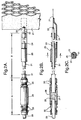
- FIG. 2A, 2B, and 2C three views with partial cutaways are shown of fittings for electrical cables and connections to the heater element of the present invention.
- the top of the heater element 21 is connected to a high temperature lead cable 22 by a weld connection 33.
- a waterproof interface between the cable and heater A is within a transition zone. Above the transition zone, an inexpensive cable such as a polyethylene coated copper wire could be used.
- An electrically insulated high temperature section B extends from the waterproof interface to the heater element.
- a stiffener 24 provides support for the electrical connection to the heater element.
- the stiffener is attached to the cable by a collar 25.
- the collar is an electrically insulating collar.
- the water proof interface includes a coupling 26 around a soldered connection 27, the soldered connection providing continuity between the high temperature lead cable 22 and a low temperature lead cable 28.
- the coupling is threaded to swedge fittings 30, which may be brass fittings, and which provide a friction fitting to each of the high temperature lead sheath 31 and the low temperature lead sheath 23.
- Cable 23 goes from the surface to just above the top of the heater and cam be a copper core-copper sheathed mineral insulated cable. This type of cable is preferred because of its ability to carry very large amounts of electrical power, and because it is waterproof. Although the cable can withstand high temperatures, it is used at temperatures below the boiling point of water due to corrosion rates.
- a waterproof splice (A) terminates the mineral insulated cable 23 and forms a transition to a nickel or nichrome clad-nickel electrode 22 that is welded 33 to the upper part of the heater 21.
- the nickel hot electrode 22 can be insulated with a TEFLON sleeve 31 to prevent corrosion of the nickel electrode and provide a waterproof seal at the lower end of the cable transition 30 (TEFLON is a trademark).
- Stiffening arm 24 provides support to the TEFLON sleeved nickel electrode 22 during installation of the heater into a wellbore.
- the waterproof splice A can be about two to twenty feet above the top of the heater element.
- the water proof splice is far enough away from the heater so that the water proof splice remains at a temperature below the boiling point of water.
- the TEFLON coated high temperature lead is, at one point, exposed to the boiling point of water, and is easily capable of handling this environment.
- the lower (hotter) portion of the high temperature lead sheath 31 will eventually melt away, leaving exposed high temperature lead. Providing the TEFLON coating to this point ensures that the TEFLON extends past the point where the temperature is at the boiling point of water.
- the high temperature lead sheathing could be any coating which would protect the high temperature lead from corrosion at temperatures of the boiling point of water or less, and would either withstand higher temperatures or melt away and not cause any corrosion at higher temperatures.
- Heat resistant resins are preferred because they provide a greater length of protected high temperature lead which could be helpful if the point at which the temperature is the boiling point of water moves.
- Acceptable high temperature resins include polyimide, polyamide-imide, and polyetheretherketone.
- the high temperature lead sheath is separated from the high temperature lead by mineral insulation such as magnesium oxide. Copper leads are acceptable and effective for the low temperature leads, but nickel or nickel-chromium clad nickel are preferred for the high temperature leads.
- a plurality of elongate electrical heating elements are placed in the wellbore to form the heater, with the elements connected at the lower portion of the wellbore, and different phases of alternating electrical power applied the elements. At least six elements are preferred in order to provide heat around the entire circumference of the wellbore.
- the heating elements can be, for example, stainless steel wire, nickel-chrome alloy wire or carbon fiber elements.
- the wires are preferably between about 0.2 and about 0.8 mm in diameter and more preferably about 0.3 mm in diameter. Thicker elements provided greater allowances for corrosion, but at the expense of greater current requirements and greater material costs. Thickness of the element is chosen to result in a voltage requirement at the targeted heat flux which is not excessively low or high. For example, a voltage differential of about 60 to about 960 volts AC between the upper ends of two elements within a wellbore which have connected lower ends would be preferred.
- heater elements of stainless steel of, for example, grades 304, 316, or 310 are preferred.
- Stainless steels are not excessively expensive, and would withstand exposure to elements that may be present during start-up phases for long enough to get the elements up to elevated temperatures, and sufficiently low corrosion rates when exposed to most borehole environments for extend periods of time at elevated temperatures.
- Carbon steels could be used as heater elements for applications where heat does not have to be provided for extended periods of time. For shallow applications such as soil remediation, nichrome 80 is preferred.
- Thermocouples for control of the heaters could be provided within the wellbore, either inside of the ring of heater elements, outside of the elements, or attached to the heater elements.
- the thermocouples could be, for example, secured to one of the electrically insulating spacers.
- the thermocouple could be used to monitor the operation, or to control electrical power applied to the heater element.
- multiple thermocouples could be provided and the control temperature selected from the thermocouples. The selection could be based on a maximum temperature, an average temperature, or a combination such as an average of the highest two or three temperatures.
- the heater elements of the present invention can be made to a wide variety of lengths because of the flexibility to select different combinations of voltages and diameters of the heater elements. Heaters as short as two meters can be used, and as long as 700 meters could be provided.
- a borehole within which the heater of the present invention is placed may be cased and cemented for at least a portion of the borehole above the heater, to ensure isolation of the formation to be heated.
- the borehole may be filled with sand or a bentonite slurry to the surface. The bentonite slurry prevents water ingress from above.
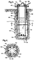
- Heater elements 101 are provided with electrical leads to the elements 102 which are larger in diameter than the heater elements, but can be of the same material.
- the number of elements is preferably between two and six.
- the electrical leads are shown extending to individual heater elements, but a spacer could be provided wherein only one electrical lead is provided for each phase of electrical energy, and the power is applied in parallel or series to different heater elements.
- the borehole within which the heater is placed is preferably between about 5 and about 20 centimeters in diameter, and the heater element are preferably placed between about one half and about one centimeter from the wall of the borehole.
- the elements are preferably separated by between about four and about eighteen centimeters.
- the heater elements are not individually electrically insulated, but rely on the electrical insulating properties of electrically insulating filler material surrounding the elements.
- a casing 103 is provided at the surface for isolation, but preferably does not extend to the soil to be heated 104, but only through an overburden 106.
- Sand or a hydraulic or ceramic cement 105 is shown surrounding the heater elements. When the soil is to be heated to the surface, a short tube could be provided to provide a stable flange for securing the tops of the heater elements.
- a flange 107 is shown with insulating sleeves 108 around the electrical leads to the heater elements.
- Power supply wires 109 provide electrical power to the electrical leads, and are secured by nuts 110.
- An electrical insulating spacer 111 provides separation of the electrical elements within the borehole.
- One electrical insulating spacer is shown, but more than one can be provided, and preferably, one is provided each three to ten meters within the wellbore. Further, the electrical insulating spacer is shown within the heater section, but one or more can also be provided in the electrical lead-in section about the heaters.
- the electrical insulating spacers can be made from an inexpensive plastic, and do not necessarily have to withstand the elevated operating temperatures. The spacers only need to hold the heater elements in place while the filler material is placed around the elements. Alternatively the spacers could be made from ceramics such as alumina, or machineable ceramics such as MACOR (MACOR is a trademark).
- the lower ends of the heater elements can be connected with an electrically conducting connector 112.
- the electrically conducting connector can connect all of the elements, or a combination of elements such that each of the elements has electrical continuity necessary for current to pass through the elements.
- the electrically conducting connector optionally has a cup 113 for securing the connector to a tube for lowering the elements, connector and spacer down the borehole.
- a tubing from, for example, a coiled tubing unit could be placed within the cup 113, and the cup held to the coiled tubing either by, for example, a friction fit which could be broken by pressure from with the coiled tubing, or the tubing could be held to the cup by tension from the heater elements as the connector is lowered into the borehole.
- the electrically conducting connector is shown at the bottom of the wellbore, with each heater element extending uniformly down the heated portion of the wellbore. But the number and/or heat duties of the heater elements can vary along the length of the heater. The diameters of the heating elements can vary along the length of the heater to tailor the heat deposition to a desired profile.
- Heater elements 101 are separated by insulating spacer 111, with the electrically insulating filler such as sand or cement 105 surrounding the spacer and heater elements.
- the soil to be heated 104 surrounds the heater.
- the electrically insulating spacer 111 is shown as being in two parts, with mating tongues and groves to allow the spacers to be slipped inside the heater elements and around a tube when the tube is being used to lower the heater elements into the borehole.
- a tie wrap 201 can be used to secure the heater elements in notches within the spacer.
- the spacer may be secured vertically to the heater elements by friction, or may be held vertically by clamps (not shown) placed above, or above and below the spacer on one or more of the heater elements.
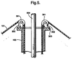
- Heater elements 101 are strung over pullies 301, the pullies mounted on brackets 302 which are set on a flange 303.
- the flange 303 is mounted on the casing 103, which is equipped with a mating flange.
- the heater elements 101 are rolling off spools (not shown) and can be maintained in slight tension to prevent entanglement of the heater elements within the borehole.
- a coiled tubing 304 is shown extending into the borehole. The coiled tubing can be used to place the heater elements and electrical leads within the borehole, and then used to fill the borehole with the electrically insulating filler as it is removed.
- the heating elements can be of a wide variety of lengths and a wide variety of distances down a borehole.
- the heater may be 400 meters long.
- the heater may be only two or three meters long, although longer heater elements are more advantageously provided by the present invention.
- the heaters may be provided an extended distance down the borehole.
- an oil shale formation may be heated which lies under 400 meters of overburden.
- the heater elements and/or electrical leads may be required to be of larger diameter or may need to be made of a material which has greater strength because these elements must be self supporting until the electrically insulating filler is placed around the elements.
- the heater elements therefore do not have to be self supporting at operating temperatures because friction with the electrically insulating filler will provide vertical support for the elements.
Applications Claiming Priority (4)
| Application Number | Priority Date | Filing Date | Title |
|---|---|---|---|
| US7716098P | 1998-03-06 | 1998-03-06 | |
| US7702298P | 1998-03-06 | 1998-03-06 | |
| US77022P | 1998-03-06 | ||
| US77160P | 1998-03-06 |
Publications (2)
| Publication Number | Publication Date |
|---|---|
| EP0940558A1 true EP0940558A1 (fr) | 1999-09-08 |
| EP0940558B1 EP0940558B1 (fr) | 2005-01-19 |
Family
ID=26758783
Family Applications (1)
| Application Number | Title | Priority Date | Filing Date |
|---|---|---|---|
| EP19990200644 Expired - Lifetime EP0940558B1 (fr) | 1998-03-06 | 1999-03-05 | Appareil de chauffage de fond de puits |
Country Status (7)
| Country | Link |
|---|---|
| EP (1) | EP0940558B1 (fr) |
| CN (1) | CN1232718C (fr) |
| AU (1) | AU746983B2 (fr) |
| CA (1) | CA2264354C (fr) |
| DE (1) | DE69923247T2 (fr) |
| JO (1) | JO2077B1 (fr) |
| MA (1) | MA24902A1 (fr) |
Cited By (3)
| Publication number | Priority date | Publication date | Assignee | Title |
|---|---|---|---|---|
| WO2001081713A1 (fr) * | 2000-04-24 | 2001-11-01 | Shell Internationale Research Maatschappij B.V. | Systeme et procede de chauffage electrique d'un puits |
| WO2001081715A3 (fr) * | 2000-04-24 | 2002-04-25 | Shell Int Research | Procede et systeme de traitement d'une formation contenant des hydrocarbures |
| WO2003036034A1 (fr) * | 2001-10-24 | 2003-05-01 | Shell Internationale Research Maatschappij B.V. | Sources de chaleur conductrices dans un conduit, presentant un materiau conducteur par voie electrique dans des morts-terrains |
Families Citing this family (26)
| Publication number | Priority date | Publication date | Assignee | Title |
|---|---|---|---|---|
| US6951247B2 (en) | 2001-04-24 | 2005-10-04 | Shell Oil Company | In situ thermal processing of an oil shale formation using horizontal heat sources |
| CA2524689C (fr) | 2003-04-24 | 2012-05-22 | Shell Canada Limited | Procedes thermiques pour formations souterraines |
| ATE414840T1 (de) | 2004-04-23 | 2008-12-15 | Shell Int Research | Zur erwärmung von unterirdischen formationen verwendete temperaturbegrenzte heizvorrichtungen |
| US7568526B2 (en) * | 2004-07-29 | 2009-08-04 | Tyco Thermal Controls Llc | Subterranean electro-thermal heating system and method |
| US7575053B2 (en) | 2005-04-22 | 2009-08-18 | Shell Oil Company | Low temperature monitoring system for subsurface barriers |
| EP1871986A1 (fr) * | 2005-04-22 | 2008-01-02 | Shell Internationale Research Maatschappij B.V. | Propriétés variables sur des longueurs de radiateurs à limite de température |
| US8606091B2 (en) | 2005-10-24 | 2013-12-10 | Shell Oil Company | Subsurface heaters with low sulfidation rates |
| AU2007240367B2 (en) | 2006-04-21 | 2011-04-07 | Shell Internationale Research Maatschappij B.V. | High strength alloys |
| GB2456251B (en) | 2006-10-20 | 2011-03-16 | Shell Int Research | Heating hydrocarbon containing formations in a spiral startup staged sequence |
| US7832484B2 (en) | 2007-04-20 | 2010-11-16 | Shell Oil Company | Molten salt as a heat transfer fluid for heating a subsurface formation |
| CA2698564C (fr) | 2007-10-19 | 2014-08-12 | Shell Internationale Research Maatschappij B.V. | Oxydation in situ de formations de sous-surface |
| US8162405B2 (en) | 2008-04-18 | 2012-04-24 | Shell Oil Company | Using tunnels for treating subsurface hydrocarbon containing formations |
| CA2738805A1 (fr) | 2008-10-13 | 2010-04-22 | Shell Internationale Research Maatschappij B.V. | Systemes de fluide de transfert chauffe en circulation utilise pour traiter une formation souterraine |
| US8851170B2 (en) | 2009-04-10 | 2014-10-07 | Shell Oil Company | Heater assisted fluid treatment of a subsurface formation |
| EP2486573A4 (fr) * | 2009-10-09 | 2014-05-28 | Shell Oil Co | Jonction de couplage compactée pour le couplage de conducteurs isolés |
| US8701769B2 (en) | 2010-04-09 | 2014-04-22 | Shell Oil Company | Methods for treating hydrocarbon formations based on geology |
| US8631866B2 (en) | 2010-04-09 | 2014-01-21 | Shell Oil Company | Leak detection in circulated fluid systems for heating subsurface formations |
| US9033042B2 (en) | 2010-04-09 | 2015-05-19 | Shell Oil Company | Forming bitumen barriers in subsurface hydrocarbon formations |
| US8820406B2 (en) | 2010-04-09 | 2014-09-02 | Shell Oil Company | Electrodes for electrical current flow heating of subsurface formations with conductive material in wellbore |
| US9016370B2 (en) | 2011-04-08 | 2015-04-28 | Shell Oil Company | Partial solution mining of hydrocarbon containing layers prior to in situ heat treatment |
| CA2850741A1 (fr) | 2011-10-07 | 2013-04-11 | Manuel Alberto GONZALEZ | Agencement de dilatation thermique pour systemes a ecoulement de fluide utilises pour l'echauffement de formations souterraines |
| CN104684120A (zh) * | 2015-01-11 | 2015-06-03 | 淄博蜀东有机玻璃有限公司 | 一种纳米加热片 |
| CN105010002A (zh) * | 2015-07-10 | 2015-11-04 | 重庆天开园林股份有限公司 | 一种加热装置及方法 |
| CN106761636B (zh) * | 2016-12-03 | 2023-05-05 | 吉林大学 | 一种深层油页岩原位开采涡流加热器 |
| CN110863808B (zh) * | 2019-11-21 | 2021-09-07 | 西南石油大学 | 一种电加热增强水驱效率的稠油开采方法 |
| GB2605062A (en) * | 2020-01-17 | 2022-09-21 | Halliburton Energy Services Inc | Voltage to accelerate/decelerate expandable metal |
Citations (5)
| Publication number | Priority date | Publication date | Assignee | Title |
|---|---|---|---|---|
| US2208087A (en) * | 1939-11-06 | 1940-07-16 | Carlton J Somers | Electric heater |
| US2350429A (en) * | 1941-05-17 | 1944-06-06 | Donald F Troupe | Electrohydrothermic oil-well processor |
| US2362680A (en) * | 1941-05-17 | 1944-11-14 | Donald F Troupe | Electrothermic oil well processor |
| US2500513A (en) * | 1946-03-22 | 1950-03-14 | Hyman D Bowman | Well heater |
| US5065818A (en) * | 1991-01-07 | 1991-11-19 | Shell Oil Company | Subterranean heaters |
-
1999
- 1999-03-01 MA MA25478A patent/MA24902A1/fr unknown
- 1999-03-03 AU AU18573/99A patent/AU746983B2/en not_active Ceased
- 1999-03-04 CA CA 2264354 patent/CA2264354C/fr not_active Expired - Fee Related
- 1999-03-04 JO JO19992077A patent/JO2077B1/en active
- 1999-03-05 DE DE69923247T patent/DE69923247T2/de not_active Expired - Lifetime
- 1999-03-05 CN CN 99102078 patent/CN1232718C/zh not_active Expired - Fee Related
- 1999-03-05 EP EP19990200644 patent/EP0940558B1/fr not_active Expired - Lifetime
Patent Citations (5)
| Publication number | Priority date | Publication date | Assignee | Title |
|---|---|---|---|---|
| US2208087A (en) * | 1939-11-06 | 1940-07-16 | Carlton J Somers | Electric heater |
| US2350429A (en) * | 1941-05-17 | 1944-06-06 | Donald F Troupe | Electrohydrothermic oil-well processor |
| US2362680A (en) * | 1941-05-17 | 1944-11-14 | Donald F Troupe | Electrothermic oil well processor |
| US2500513A (en) * | 1946-03-22 | 1950-03-14 | Hyman D Bowman | Well heater |
| US5065818A (en) * | 1991-01-07 | 1991-11-19 | Shell Oil Company | Subterranean heaters |
Cited By (4)
| Publication number | Priority date | Publication date | Assignee | Title |
|---|---|---|---|---|
| WO2001081713A1 (fr) * | 2000-04-24 | 2001-11-01 | Shell Internationale Research Maatschappij B.V. | Systeme et procede de chauffage electrique d'un puits |
| WO2001081715A3 (fr) * | 2000-04-24 | 2002-04-25 | Shell Int Research | Procede et systeme de traitement d'une formation contenant des hydrocarbures |
| US6959761B2 (en) * | 2000-04-24 | 2005-11-01 | Shell Oil Company | In situ thermal processing of a coal formation with a selected ratio of heat sources to production wells |
| WO2003036034A1 (fr) * | 2001-10-24 | 2003-05-01 | Shell Internationale Research Maatschappij B.V. | Sources de chaleur conductrices dans un conduit, presentant un materiau conducteur par voie electrique dans des morts-terrains |
Also Published As
| Publication number | Publication date |
|---|---|
| CN1232718C (zh) | 2005-12-21 |
| AU1857399A (en) | 1999-09-23 |
| CN1236858A (zh) | 1999-12-01 |
| DE69923247D1 (de) | 2005-02-24 |
| CA2264354A1 (fr) | 1999-09-06 |
| JO2077B1 (en) | 2000-05-21 |
| DE69923247T2 (de) | 2006-01-12 |
| CA2264354C (fr) | 2007-11-06 |
| EP0940558B1 (fr) | 2005-01-19 |
| AU746983B2 (en) | 2002-05-09 |
| MA24902A1 (fr) | 2000-04-01 |
Similar Documents
| Publication | Publication Date | Title |
|---|---|---|
| CA2264354C (fr) | Appareil de chauffage electrique | |
| US6540018B1 (en) | Method and apparatus for heating a wellbore | |
| US6269876B1 (en) | Electrical heater | |
| US5065818A (en) | Subterranean heaters | |
| US6360819B1 (en) | Electrical heater | |
| US4570715A (en) | Formation-tailored method and apparatus for uniformly heating long subterranean intervals at high temperature | |
| US5060287A (en) | Heater utilizing copper-nickel alloy core | |
| US4572299A (en) | Heater cable installation | |
| AU777152B2 (en) | Electrical well heating system and method | |
| CA2850737C (fr) | Epissure integrale pour des conducteurs isoles | |
| AU2001260243A1 (en) | Electrical well heating system and method | |
| US10201042B1 (en) | Flexible helical heater | |
| AU2010303252B2 (en) | Press-fit coupling joint for joining insulated conductors | |
| RU2570508C2 (ru) | Изоляционные блоки и способы их установки в нагревателях с изолированным проводником | |
| CA2055548C (fr) | Appareil de chauffage electrique a basse resistance | |
| CA1250340A (fr) | Methode et dispositif pour chauffer uniformement de longs intervalles geologiques | |
| CA1250339A (fr) | Isolant pour cable chauffant |
Legal Events
| Date | Code | Title | Description |
|---|---|---|---|
| PUAI | Public reference made under article 153(3) epc to a published international application that has entered the european phase |
Free format text: ORIGINAL CODE: 0009012 |
|
| AK | Designated contracting states |
Kind code of ref document: A1 Designated state(s): BE DE ES FR GB IT NL SE |
|
| AX | Request for extension of the european patent |
Free format text: AL;LT;LV;MK;RO;SI |
|
| 17P | Request for examination filed |
Effective date: 20000203 |
|
| AKX | Designation fees paid |
Free format text: BE DE ES FR GB IT NL SE |
|
| 17Q | First examination report despatched |
Effective date: 20011011 |
|
| RTI1 | Title (correction) |
Free format text: WELLBORE ELECTRICAL HEATER |
|
| GRAP | Despatch of communication of intention to grant a patent |
Free format text: ORIGINAL CODE: EPIDOSNIGR1 |
|
| GRAS | Grant fee paid |
Free format text: ORIGINAL CODE: EPIDOSNIGR3 |
|
| GRAA | (expected) grant |
Free format text: ORIGINAL CODE: 0009210 |
|
| AK | Designated contracting states |
Kind code of ref document: B1 Designated state(s): BE DE ES FR GB IT NL SE |
|
| PG25 | Lapsed in a contracting state [announced via postgrant information from national office to epo] |
Ref country code: IT Free format text: LAPSE BECAUSE OF FAILURE TO SUBMIT A TRANSLATION OF THE DESCRIPTION OR TO PAY THE FEE WITHIN THE PRESCRIBED TIME-LIMIT;WARNING: LAPSES OF ITALIAN PATENTS WITH EFFECTIVE DATE BEFORE 2007 MAY HAVE OCCURRED AT ANY TIME BEFORE 2007. THE CORRECT EFFECTIVE DATE MAY BE DIFFERENT FROM THE ONE RECORDED. Effective date: 20050119 Ref country code: BE Free format text: LAPSE BECAUSE OF FAILURE TO SUBMIT A TRANSLATION OF THE DESCRIPTION OR TO PAY THE FEE WITHIN THE PRESCRIBED TIME-LIMIT Effective date: 20050119 |
|
| REG | Reference to a national code |
Ref country code: GB Ref legal event code: FG4D |
|
| REF | Corresponds to: |
Ref document number: 69923247 Country of ref document: DE Date of ref document: 20050224 Kind code of ref document: P |
|
| PG25 | Lapsed in a contracting state [announced via postgrant information from national office to epo] |
Ref country code: SE Free format text: LAPSE BECAUSE OF FAILURE TO SUBMIT A TRANSLATION OF THE DESCRIPTION OR TO PAY THE FEE WITHIN THE PRESCRIBED TIME-LIMIT Effective date: 20050419 |
|
| PG25 | Lapsed in a contracting state [announced via postgrant information from national office to epo] |
Ref country code: ES Free format text: LAPSE BECAUSE OF FAILURE TO SUBMIT A TRANSLATION OF THE DESCRIPTION OR TO PAY THE FEE WITHIN THE PRESCRIBED TIME-LIMIT Effective date: 20050430 |
|
| PLBE | No opposition filed within time limit |
Free format text: ORIGINAL CODE: 0009261 |
|
| STAA | Information on the status of an ep patent application or granted ep patent |
Free format text: STATUS: NO OPPOSITION FILED WITHIN TIME LIMIT |
|
| ET | Fr: translation filed | ||
| 26N | No opposition filed |
Effective date: 20051020 |
|
| REG | Reference to a national code |
Ref country code: FR Ref legal event code: PLFP Year of fee payment: 18 |
|
| REG | Reference to a national code |
Ref country code: FR Ref legal event code: PLFP Year of fee payment: 19 |
|
| PGFP | Annual fee paid to national office [announced via postgrant information from national office to epo] |
Ref country code: NL Payment date: 20170320 Year of fee payment: 19 Ref country code: DE Payment date: 20170228 Year of fee payment: 19 Ref country code: FR Payment date: 20170213 Year of fee payment: 19 |
|
| PGFP | Annual fee paid to national office [announced via postgrant information from national office to epo] |
Ref country code: GB Payment date: 20170301 Year of fee payment: 19 |
|
| REG | Reference to a national code |
Ref country code: DE Ref legal event code: R119 Ref document number: 69923247 Country of ref document: DE |
|
| REG | Reference to a national code |
Ref country code: NL Ref legal event code: MM Effective date: 20180401 |
|
| GBPC | Gb: european patent ceased through non-payment of renewal fee |
Effective date: 20180305 |
|
| PG25 | Lapsed in a contracting state [announced via postgrant information from national office to epo] |
Ref country code: NL Free format text: LAPSE BECAUSE OF NON-PAYMENT OF DUE FEES Effective date: 20180401 |
|
| PG25 | Lapsed in a contracting state [announced via postgrant information from national office to epo] |
Ref country code: DE Free format text: LAPSE BECAUSE OF NON-PAYMENT OF DUE FEES Effective date: 20181002 |
|
| PG25 | Lapsed in a contracting state [announced via postgrant information from national office to epo] |
Ref country code: GB Free format text: LAPSE BECAUSE OF NON-PAYMENT OF DUE FEES Effective date: 20180305 |
|
| PG25 | Lapsed in a contracting state [announced via postgrant information from national office to epo] |
Ref country code: FR Free format text: LAPSE BECAUSE OF NON-PAYMENT OF DUE FEES Effective date: 20180331 |