EP0940349B1 - Boítier composé d'éléments de boítier reliés l'un à l'autre de manière débrayable et articulée, notamment pour luminaire - Google Patents
Boítier composé d'éléments de boítier reliés l'un à l'autre de manière débrayable et articulée, notamment pour luminaire Download PDFInfo
- Publication number
- EP0940349B1 EP0940349B1 EP99400471A EP99400471A EP0940349B1 EP 0940349 B1 EP0940349 B1 EP 0940349B1 EP 99400471 A EP99400471 A EP 99400471A EP 99400471 A EP99400471 A EP 99400471A EP 0940349 B1 EP0940349 B1 EP 0940349B1
- Authority
- EP
- European Patent Office
- Prior art keywords
- box
- box according
- elastically deformable
- clipping
- deformable arm
- Prior art date
- Legal status (The legal status is an assumption and is not a legal conclusion. Google has not performed a legal analysis and makes no representation as to the accuracy of the status listed.)
- Expired - Lifetime
Links
- 238000000926 separation method Methods 0.000 claims description 9
- 230000000295 complement effect Effects 0.000 claims description 7
- 238000007598 dipping method Methods 0.000 claims 1
- 210000000056 organ Anatomy 0.000 description 5
- 230000005489 elastic deformation Effects 0.000 description 2
- 125000006850 spacer group Chemical group 0.000 description 2
- 208000029152 Small face Diseases 0.000 description 1
- 210000004027 cell Anatomy 0.000 description 1
- 230000006835 compression Effects 0.000 description 1
- 238000007906 compression Methods 0.000 description 1
- 238000010494 dissociation reaction Methods 0.000 description 1
- 230000005593 dissociations Effects 0.000 description 1
- 230000000694 effects Effects 0.000 description 1
- 238000003780 insertion Methods 0.000 description 1
- 230000037431 insertion Effects 0.000 description 1
- 238000012423 maintenance Methods 0.000 description 1
- 238000004519 manufacturing process Methods 0.000 description 1
Images


Classifications
-
- B—PERFORMING OPERATIONS; TRANSPORTING
- B65—CONVEYING; PACKING; STORING; HANDLING THIN OR FILAMENTARY MATERIAL
- B65D—CONTAINERS FOR STORAGE OR TRANSPORT OF ARTICLES OR MATERIALS, e.g. BAGS, BARRELS, BOTTLES, BOXES, CANS, CARTONS, CRATES, DRUMS, JARS, TANKS, HOPPERS, FORWARDING CONTAINERS; ACCESSORIES, CLOSURES, OR FITTINGS THEREFOR; PACKAGING ELEMENTS; PACKAGES
- B65D43/00—Lids or covers for rigid or semi-rigid containers
- B65D43/14—Non-removable lids or covers
- B65D43/16—Non-removable lids or covers hinged for upward or downward movement
- B65D43/163—Non-removable lids or covers hinged for upward or downward movement the container and the lid being made separately
- B65D43/164—Non-removable lids or covers hinged for upward or downward movement the container and the lid being made separately and connected by interfitting hinge elements integrally with the container and the lid formed respectively
-
- F—MECHANICAL ENGINEERING; LIGHTING; HEATING; WEAPONS; BLASTING
- F21—LIGHTING
- F21V—FUNCTIONAL FEATURES OR DETAILS OF LIGHTING DEVICES OR SYSTEMS THEREOF; STRUCTURAL COMBINATIONS OF LIGHTING DEVICES WITH OTHER ARTICLES, NOT OTHERWISE PROVIDED FOR
- F21V17/00—Fastening of component parts of lighting devices, e.g. shades, globes, refractors, reflectors, filters, screens, grids or protective cages
- F21V17/10—Fastening of component parts of lighting devices, e.g. shades, globes, refractors, reflectors, filters, screens, grids or protective cages characterised by specific fastening means or way of fastening
- F21V17/107—Fastening of component parts of lighting devices, e.g. shades, globes, refractors, reflectors, filters, screens, grids or protective cages characterised by specific fastening means or way of fastening using hinge joints
-
- F—MECHANICAL ENGINEERING; LIGHTING; HEATING; WEAPONS; BLASTING
- F21—LIGHTING
- F21V—FUNCTIONAL FEATURES OR DETAILS OF LIGHTING DEVICES OR SYSTEMS THEREOF; STRUCTURAL COMBINATIONS OF LIGHTING DEVICES WITH OTHER ARTICLES, NOT OTHERWISE PROVIDED FOR
- F21V17/00—Fastening of component parts of lighting devices, e.g. shades, globes, refractors, reflectors, filters, screens, grids or protective cages
- F21V17/10—Fastening of component parts of lighting devices, e.g. shades, globes, refractors, reflectors, filters, screens, grids or protective cages characterised by specific fastening means or way of fastening
- F21V17/16—Fastening of component parts of lighting devices, e.g. shades, globes, refractors, reflectors, filters, screens, grids or protective cages characterised by specific fastening means or way of fastening by deformation of parts; Snap action mounting
- F21V17/164—Fastening of component parts of lighting devices, e.g. shades, globes, refractors, reflectors, filters, screens, grids or protective cages characterised by specific fastening means or way of fastening by deformation of parts; Snap action mounting the parts being subjected to bending, e.g. snap joints
-
- B—PERFORMING OPERATIONS; TRANSPORTING
- B65—CONVEYING; PACKING; STORING; HANDLING THIN OR FILAMENTARY MATERIAL
- B65D—CONTAINERS FOR STORAGE OR TRANSPORT OF ARTICLES OR MATERIALS, e.g. BAGS, BARRELS, BOTTLES, BOXES, CANS, CARTONS, CRATES, DRUMS, JARS, TANKS, HOPPERS, FORWARDING CONTAINERS; ACCESSORIES, CLOSURES, OR FITTINGS THEREFOR; PACKAGING ELEMENTS; PACKAGES
- B65D2543/00—Lids or covers essentially for box-like containers
- B65D2543/00009—Details of lids or covers for rigid or semi-rigid containers
- B65D2543/00953—Sealing means
- B65D2543/00962—Sealing means inserted
- B65D2543/00972—Collars or rings
Definitions
- the present invention relates generally to the housings of the kind comprising two housing elements reported one on the other following a confrontation surface, jointly defining any housing, and releasably connected to each other in each of two opposite assembly areas.
- One of the housing elements constituting such a housing then constitutes a base, suitable for fixing the assembly to any support, while that, acting as a cover with respect to this base, the other of these housing elements constitutes for example a verrine.
- each housing elements comprises, on the one hand, at least one member latching, by which it is able to cooperate in hooking with a member additional snap-in provided in correspondence on the other element of housing, and, on the other hand, at least one journal member, by which it is able to cooperate in pivoting with a journal member complementary also provided in correspondence on the other element of housing, and in that, for at least one of the housing elements, the member at least, is carried by an elastically deformable arm, in being, for example, disposed at the end thereof.
- snap-in means which make it very easy to report and quickly these housing elements one on the other, by a simple engagement by force of one on the other, and, on the other hand, journaling means, which allow to proceed, if desired, to an opening of the assembly without complete separation of the two housing elements, one with respect to the other, by ensuring only on one side the separation of these while leaving hinged to each other on the other side.
- the two assembly zones of the housing according to the invention thus both using snap-fastening means and journalling means, they can each be used interchangeably, and alternatively, of opening zone or articulation zone, so that the opening of this case can advantageously intervene either side or the other.
- both of these assembly zones are each advantageously capable of allowing a very wide opening of the housing according to the invention.
- this opening is thus likely to occur on at least 180 °.
- journaling of the housing element, the latching member of which is worn by an elastically deformable arm forms a single piece with this latching member.
- this journal member is dissociated from this member and forms a separate part therefrom.
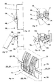
- the housing 10 is of kind comprising, overall, two elements of housings 10A, 10B, which, reported one on the other along a confrontation surface 11, defining together any housing 12, are connected to each other so disengageable in each of two opposite assembly zones 14.
- a housing 10 for lighting It is, for example, a housing 10 for lighting.
- the housing element 10A then constitutes a base, which is suitable for allow the whole to be reported on any medium, and, intervening at like a cover, the housing element 10B then constitutes jointly a verrine.
- the housing elements 10A, 10B will also not be described in all their details here.
- the housing element 10A forms, externally, projecting on its side wall, in the vicinity of its outlet 15, but slightly behind it, a gutter 16, which runs along its perimeter, being open from the side of confrontation surface 11, to serve as a housing for a seal seal 17, and whose free edge belongs to the confrontation surface 11, and that, jointly, the housing element 10B forms, throughout its perimeter, at its own outlet 18, in correspondence with the gutter 16 of the housing element 10A, a tongue 19, by which it is able to act in compression on the seal 17, with, externally, projecting on its side wall, a flange 20, which, intended to be applied on the edge free from the gutter 16 of the housing element 10A, belongs, like this one, at the confrontation surface 11, and which, in practice, is locally interrupted at the right of each of the two assembly zones 14.
- the two areas of assembly 14 intervene, back to back, in the middle zone of two faces opposite housing elements 10A, 10B, for example in the area median of their small faces, each extending on either side of the confrontation area 11.
- these two assembly zones 14, only one of which is visible in the figures, have identical constitutions.
- each of the housing elements 10A, 10B comprises, on the one hand, at least one member 22A, 22B, by which it is able to cooperate in picking with a complementary latching member 22B, 22A provided in correspondence on the other housing element 10B, 10A, and, on the other hand, at least one member journal 23A, 23B, by which it is able to cooperate in pivoting with a complementary journalling member 23B, 23A also provided in correspondence on the other housing element 10B, 10A, and, for one at less of the housing elements 10A, 10B, the latching member 22A, 22B, at less, is carried by an elastically deformable arm 24.
- only the latching member 22B of the housing element 10B is carried by an elastically arm deformable 24, and it is disposed at the end thereof.
- the latching member 22A of the other housing element 10A, 10B, in the case of the housing element 10A, is, itself, rigidly linked thereto.
- the two latching members 22B extend back to back at the free end of the elastically deformable arm 24 who wears them.
- the elastically deformable arm 24 is connected to the element of housing 10A, 10B which carries it, in this case the housing element 10B, at a distance of the confrontation surface 11, and it extends cantilevered towards it.
- the elastically deformable arm 24 extends beyond the confrontation surface 11, and, therefore, beyond the flange 20 of the housing element 10B
- the arm elastically deformable 24 extends even beyond the free edge of the tab 19 of the housing element 10B.
- the arm resiliently deformable 24 is split into parallel flanges 26 which, at their end free, are connected to each other by the same cross member 27.
- six flanges 26 are provided for the constitution of the elastically deformable arm 24, and they are divided into two groups of three, with, between these two groups, for reasons which Appear below, a space 28 sufficient to allow the insertion of a any tool, not shown.
- the flanges 26 of the same group are, from their root, and over a fraction of their length, linked in pairs by spacers 29 which unify them.
- the flanges 26 constituting the resilient arm deformable 24 extend perpendicular to the side wall of the element of housing 10B, and perpendicular to the confrontation surface 11; jointly, the crosspiece 27 which connects these flanges 26 extends parallel to the side wall of the housing element 10B and parallel to the surface confrontation 11.
- the latching members 22B carried by the elastically deformable arm 24 are lugs which make laterally projecting at the free end of this elastically deformable arm 24, being each respectively constituted by the corresponding end of the cross member 27 provided at this level.
- journal members 23B of the housing element 10B of which the snap-fastening members 22B are carried by an elastically arm deformable 24 are dissociated from these latching members 22B and form thus separate parts of these.
- these latching members 22B, on the one hand, and these journaling members 23B, on the other hand, can advantageously have separate profiles.
- the lugs forming the locking members 22B carried by the arm elastically deformable 24, that is to say the pins forming the organs latching 22B of the housing element 10B have, overall, in section transverse, a quarter-circle profile, with a curvilinear side 30 which extends from the side opposite to the side wall of the housing element 10B, a flat 31, which extends parallel to the confrontation surface 11, and, in square with the previous one, a flat 32, which extends from the side of the wall side of the housing element 10B.
- the snap-fastening members 22A of the other element of housing 10A, 10B in this case the housing element 10A, have, overall, cross section, an awning profile, and, as it is better visible by example in Figure 5 for one of them, they extend substantially parallel to the confrontation surface 11.
- latching members 22A On the side of their upper surface, i.e. on the side of the surface confrontation 11, these latching members 22A are, preferably, and as shown, each shot by an engagement profile 34, which generally extends obliquely towards their free end.
- the latching members 22A of the housing element 10A have, in fact, on the side of their surface upper, a dihedral profile with the point extending towards the surface confrontation 11.
- the latching members 22A of the element of housing 10A have, jointly, in cross section, in this form of production, a circular arc profile, which extends substantially over 90 °, and whose concavity is turned in the opposite direction to the confrontation surface 11, being oriented substantially at 45 ° relative to the latter.
- these latching members 22A are each backed, laterally, on the one of their sides which is the most outside, to a fixed flange 36 which stiffens them.
- these snap-fastening members 22A face each other, at a distance from each other, on their respective flanges 26, and, established at the same level, both extend generally in withdrawal with respect to the surface confrontation 11.
- a boss 37 which, to buttress the crosspiece 27 of the elastically deformable arm 24 of the housing element 10B, shape, parallel to the confrontation surface 11, and at a level lower than that latching members 22A, a shoulder 38 in an arc.
- this boss 37 is divided into flanges 39, which, parallel to each other, are offset relative to the flanges 26 forming the elastically deformable arm 24 of the housing element 10B, to be able to nest therewith.
- the cross member 27 of the elastically deformable arm 24 of the element housing 10B being stiffened by a rib 40 in space 28, the flanges 39 present in the middle zone of the boss 37 of the housing element 10A are of lesser height, so as not to interfere with this rib 40.
- each of the 23B of the housing element 10B is a protruding lug laterally on an individual support arm 41.
- this support arm 41 is rigid.
- the support arm 41 thus carrying a journal member 23B has the same configuration that the flanges 26 constituting the elastically deformable arm 24 carrying the snap members 22B, and it extends parallel thereto.
- Two journalling members 23B being provided, there is, in practice, two support arms 41, and these frame the arm elastically deformable 24 carrying the locking members 22B, at a distance from this arm elastically deformable 24.
- the pins forming the organs journal 23B have, generally, in cross section, a profile circular, and, in correspondence with each other, they each contain side opposite to the side wall of the housing element 10B, a flat 42 which extends substantially perpendicular to the confrontation surface 11.
- the lugs forming the swiveling members 23B of the housing element 10B are coaxial with the lugs forming the members 22B latching of this housing element 10B, and they extend in opposite directions to each other.
- the journal member 23A of the other housing element 10A, 10B in this case the housing element 10A, comprises, at the edge of a passage engagement 43 parallel to the confrontation surface 11, at the end of this engagement passage 43 opposite this confrontation surface 11, a rounded shoulder 44, the concavity of which generally faces the wall side of the housing element 10A, being oriented substantially at 45 ° by compared to the confrontation area 11.
- this swiveling member 23A operates at a distance from the side wall of the housing element 10A, substantially parallel to this side wall, and, like a trigger guard or a spacer, it extends between, on the one hand, the corresponding flange 36, on the side thereof opposite that on which intervenes a latching member 22A, and, on the other hand, a flange 45 parallel to the flange 36, being integral with one and the other of these flanges 36 and 45.
- the flange 45 which has a configuration similar to that flange 36, present, on its edge, on the side of the confrontation surface 11, a U-shaped notch 46, FIG. 6, capable of forming a cradle at its bottom for the corresponding journal member 23B of the housing element 10B.
- the distance D1 separating the gutter from the gutter 16 journal 23A is substantially equal to the dimension D2 of the swivel 23B at the right of its flat 42, FIG. 8, while being slightly greater than this dimension D2.
- the housing element 10A door also, beyond the flanges 45, for guiding the support arms 41 carried by the housing element 10B, flanges 47, which, parallel to flanges 45, have, like these, a configuration analogous to that of flanges 36 and 39.
- the assembly of the housing 10 according to the invention is done by simple engagement by force of one of its housing elements 10A, 10B relative to each other.
- journal members 23B of the housing element 10B engage between the bodies of journal 23A of the housing element 10A and the gutter 16 thereof, up to come to the right of the rounded shoulder 44 of these bodies of journal 23A, as can be seen for one of them in FIGS. 10 and 11.
- This tool which can for example be a simple screwdriver blade, is insert between the cross member 27 carried by the elastically deformable arm 24 and the side wall of the housing element 10B, using the space 28 provided for this effect, to leverage this cross 27 by building on this side wall.
- journal members 23A of the housing element 10A are caught under the organs of journal 23B of the housing element 10B, in favor of the shoulder rounded 44 of these, as shown for one of them in the figures 12 and 13, and they thus ensure a hold in engagement of the two elements of housing 10A, 10B relative to each other, without risk of separation untimely of these at this level.
- the opening of the housing 10 according to the invention can advantageously intervene over 180 °.
- journalling members 23B of the housing element 10B including the members 22B are carried by an elastically deformable arm 24 each form a single piece with these members, respectively 22B.
- the organ or organs at least, could be carried by an elastic arm deformable.
Landscapes
- Engineering & Computer Science (AREA)
- General Engineering & Computer Science (AREA)
- Mechanical Engineering (AREA)
- Closures For Containers (AREA)
- Non-Portable Lighting Devices Or Systems Thereof (AREA)
- Fastening Of Light Sources Or Lamp Holders (AREA)
- Buckles (AREA)
- Joints Allowing Movement (AREA)
- Packages (AREA)
- Casings For Electric Apparatus (AREA)
- Pivots And Pivotal Connections (AREA)
- Arrangement Of Elements, Cooling, Sealing, Or The Like Of Lighting Devices (AREA)
- Lighting Device Outwards From Vehicle And Optical Signal (AREA)
- Toys (AREA)
Description
Claims (24)
- Boítier du genre comportant deux éléments de boítier (10A, 10B) rapportés l'un sur l'autre suivant une surface d'affrontement (11) et reliés l'un à l'autre de manière débrayable en chacune de deux zones d'assemblage (14) opposées, caractérisé en ce que, à chacune des zones d'assemblage (14), chacun des éléments de boítier (10A, 10B) comporte, d'une part, au moins un organe d'encliquetage (22A, 22B), par lequel il est apte à coopérer en crochetage avec un organe d'encliquetage (22B, 22A) complémentaire prévu en correspondance sur l'autre élément de boítier (10B, 10A), et, d'autre part, au moins un organe de tourillonnement (23A, 23B), par lequel il est apte à coopérer en pivotement avec un organe de tourillonnement (23B, 23A) complémentaire également prévu en correspondance sur l'autre élément de boítier (10B, 10A), et en ce que, pour l'un au moins des éléments de boítier (10A, 10B), l'organe d'encliquetage (22A, 22B), au moins, est porté par un bras élastiquement déformable (24) permettant la désolidarisation des éléments de boítier.
- Boítier suivant la revendication 1, caractérisé en ce que le bras élastiquement déformable (24) se raccorde à l'élément de boítier (10B) qui le porte à distance de la surface d'affrontement (11) et il s'étend en porte à faux en direction de celle-ci.
- Boítier suivant la revendication 2, caractérisé en ce que le bras élastiquement déformable (24) s'étend au-delà de la surface d'affrontement (11).
- Boítier suivant l'une quelconque des revendications 1 à 3, caractérisé en ce que le bras élastiquement déformable (24) est fractionné en flasques (26) parallèles, qui, à leur extrémité libre, sont reliés les uns aux autres par une traverse (27).
- Boítier suivant l'une quelconque des revendications 1 à 4, caractérisé en ce que l'organe d'encliquetage (22B) porté par le bras élastiquement déformable (24) est un ergot qui fait saillie latéralement.
- Boítier suivant la revendication 5, caractérisé en ce que l'ergot formant l'organe d'encliquetage (22B) porté par le bras élastiquement déformable (24) a, globalement, en section transversale, un profil en quart de cercle.
- Boítier suivant l'une quelconque des revendications 1 à 6, caractérisé en ce que l'organe d'encliquetage (228) porté par le bras élastiquement déformable (24) est disposé au bout de celui-ci.
- Boítier suivant l'une quelconque des revendications 1 à 7, caractérisé en ce que l'organe d'encliquetage (22A) de l'autre élément de boítier (10A) a globalement un profil en auvent, et il s'étend sensiblement parallèlment à la surface d'affrontement (11).
- Boítier suivant la revendication 8, caractérisé en ce que, du côté de la surface d'affrontement (11), l'organe d'encliquetage (22A) porté par l'autre élément de boítier (10A) est abattu par un profil d'engagement (34).
- Boítier suivant l'une quelconque des revendications 8, 9, caractérisé en ce que l'organe d'encliquetage (22A) de l'autre élément de boítier (10A) est rigidement lié à celui-ci.
- Boítier suivant l'une quelconque des revendications 1 à 10, caractérisé en ce que l'organe d'encliquetage (22A) de l'autre élément de boítier (10A) s'étend globalement en retrait par rapport à la surface d'affrontement (11).
- Boítier suivant l'une quelconque des revendications 1 à 11, caractérisé en ce que l'organe de tourillonnement (23B) de l'élément de boítier (10B) dont l'organe d'encliquetage (22B) est porté par un bras élastiquement déformable (24) forme une seule et même pièce avec cet organe d'encliquetage (22B).
- Boítier suivant l'une quelconque des revendications 1 à 11, caractérisé en ce que l'organe de tourillonnement (23B) de l'élément de boítier (10B) dont l'organe d'encliquetage (228) est porté par un bras élastiquement déformable (24) est dissocié de cet organe d'encliquetage (22B) et forme une pièce distincte de celui-ci.
- Boítier suivant la revendication 13, caractérisé en ce que l'organe de tourillonnement (23B) est un ergot qui fait saillie latéralement sur un arbre de support (41) individuel.
- Boítier suivant la revendication 14, caractérisé en ce que le bras de support (41) de l'organe de tourillonnement (238) est rigide.
- Boítier suivant l'une quelconque des revendications 14, 15, caractérisé en ce que l'ergot formant l'organe de tourillonnement (238) a, globalement, en section transversale, un profil circulaire, et il comporte un méplat (42) qui s'étend sensiblement perpendiculairement à la surface d'affrontement (11).
- Boítier suivant les revendications 5 et 14, prises conjointement, caractérisé en ce que l'ergot formant l'organe de tourillonnement (238) est coaxial de l'ergot formant l'organe d'encliquetage (22B).
- Boítier suivant la revendication 17, caractérisé en ce que l'ergot formant l'organe de tourillonnement (23B) et l'ergot formant l'organe d'encliquetage (22B) s'étendent en directions opposées l'un par rapport à l'autre.
- Boítier suivant l'une quelconque des revendications 13 à 18, caractérisé en ce que l'organe de tourillonnement (23A) de l'autre élément de boítier (10A) comporte, en bordure d'un passage d'engagement (43), un épaulement arrondi (44), dont la concavité est globalement tournée vers la paroi latérale de cet élément de boítier (10A).
- Boítier suivant l'une quelconque des revendications 1 à 19, caractérisé en ce que, pour chacune des deux zones d'assemblage (14), il y a deux organes d'encliquetage (228) disposés au bout d'un même bras élastiquement déformable (24) sur l'élément de boítier (10B) concerné, avec, en correspondance, sur l'autre élément de boítier (10A), deux organes d'encliquetage (22A) complémentaires.
- Boítier suivant l'une quelconque des revendications 1 à 20, caractérisé en ce que, pour chacune des deux zones d'assemblage (14), il y a deux organes de tourillonnement (23A, 23B) sur chacun des éléments de boítier (10A,10B).
- Boítier suivant l'une quelconque des revendications 20, 21, caractérisé en ce que les deux organes d'encliquetage (22B) s'étendent dos à dos à l'extrémité libre du bras élastiquement déformable (24) qui les porte.
- Boítier suivant l'une quelconque des revendications 1 à 22, caractérisé en ce que l'élément de boítier (10B) comportant un bras élastiquement déformable (24) au bout duquel est disposé au moins un organe d'encliquetage (22B) intervient à la manière d'un couvercle.
- Boítier suivant l'une quelconque des revendications 1 à 23, caractérisé en ce que les deux zones d'assemblage (14) ont des constitutions identiques.
Applications Claiming Priority (2)
| Application Number | Priority Date | Filing Date | Title |
|---|---|---|---|
| FR9802475 | 1998-03-02 | ||
| FR9802475A FR2775466B1 (fr) | 1998-03-02 | 1998-03-02 | Boitier compose d'elements de boitier relies l'un a l'autre de maniere debrayable et articulee, notamment pour luminaire |
Publications (2)
| Publication Number | Publication Date |
|---|---|
| EP0940349A1 EP0940349A1 (fr) | 1999-09-08 |
| EP0940349B1 true EP0940349B1 (fr) | 2004-12-15 |
Family
ID=9523514
Family Applications (1)
| Application Number | Title | Priority Date | Filing Date |
|---|---|---|---|
| EP99400471A Expired - Lifetime EP0940349B1 (fr) | 1998-03-02 | 1999-02-26 | Boítier composé d'éléments de boítier reliés l'un à l'autre de manière débrayable et articulée, notamment pour luminaire |
Country Status (8)
| Country | Link |
|---|---|
| US (1) | US6186350B1 (fr) |
| EP (1) | EP0940349B1 (fr) |
| AT (1) | ATE284822T1 (fr) |
| BR (1) | BR9900471A (fr) |
| DE (1) | DE69922563T2 (fr) |
| ES (1) | ES2232090T3 (fr) |
| FR (1) | FR2775466B1 (fr) |
| HU (1) | HU221398B1 (fr) |
Families Citing this family (6)
| Publication number | Priority date | Publication date | Assignee | Title |
|---|---|---|---|---|
| US20040000030A1 (en) * | 2002-05-09 | 2004-01-01 | Pleiman Brian R. | Multifunction container hinge |
| US20040182872A1 (en) * | 2003-01-29 | 2004-09-23 | Claude Lessard | Tamper-resistant container |
| US7841487B2 (en) * | 2004-11-01 | 2010-11-30 | Buckhorn, Inc. | Molded container with hinged lids having a knuckle and pin connection |
| FR2893593B1 (fr) * | 2005-11-21 | 2008-02-01 | Fors France Sa | Boitier antivol |
| US8505768B2 (en) * | 2009-12-02 | 2013-08-13 | Envionmental Dining, LLC | Food tray |
| DK178731B1 (en) * | 2015-03-04 | 2016-12-12 | Plastpack Defence Aps | Lightweight ammunition box |
Family Cites Families (9)
| Publication number | Priority date | Publication date | Assignee | Title |
|---|---|---|---|---|
| US3663990A (en) * | 1969-12-11 | 1972-05-23 | Pacific Associated Lighting In | Hinge |
| US4282983A (en) * | 1980-07-14 | 1981-08-11 | Owens-Illinois, Inc. | Container with improved spring-like hinge |
| US4349120A (en) * | 1981-06-10 | 1982-09-14 | Bay State Plastics Corp. | Plastic box hinge |
| US4549670A (en) * | 1984-12-19 | 1985-10-29 | Maclean-Fogg Company | Hinged tissue cassette apparatus |
| US5505328A (en) * | 1991-07-22 | 1996-04-09 | Woods & Brooks Ltd. | Modular container apparatus |
| ITTO930066A1 (it) | 1992-02-12 | 1994-08-05 | Fluoroware Inc | Cerniera perfezionata per scatola ribaltabile. |
| US5529205A (en) * | 1994-12-14 | 1996-06-25 | Carex Inc. | Hinge assembly for a container |
| US5577628A (en) * | 1995-09-13 | 1996-11-26 | Tucker Housewares | Hamper with bi-directional opening lid |
| NL1001920C2 (nl) * | 1995-12-18 | 1997-06-19 | Dsm Nv | Doos en daarvoor bestemde verbindingsmiddelen. |
-
1998
- 1998-03-02 FR FR9802475A patent/FR2775466B1/fr not_active Expired - Fee Related
-
1999
- 1999-02-26 DE DE69922563T patent/DE69922563T2/de not_active Expired - Fee Related
- 1999-02-26 ES ES99400471T patent/ES2232090T3/es not_active Expired - Lifetime
- 1999-02-26 EP EP99400471A patent/EP0940349B1/fr not_active Expired - Lifetime
- 1999-02-26 AT AT99400471T patent/ATE284822T1/de not_active IP Right Cessation
- 1999-03-01 HU HU9900485A patent/HU221398B1/hu not_active IP Right Cessation
- 1999-03-02 US US09/260,485 patent/US6186350B1/en not_active Expired - Fee Related
- 1999-03-02 BR BR9900471-2A patent/BR9900471A/pt not_active IP Right Cessation
Also Published As
| Publication number | Publication date |
|---|---|
| FR2775466A1 (fr) | 1999-09-03 |
| DE69922563D1 (de) | 2005-01-20 |
| HU221398B1 (en) | 2002-09-28 |
| US6186350B1 (en) | 2001-02-13 |
| EP0940349A1 (fr) | 1999-09-08 |
| HUP9900485A2 (hu) | 1999-10-28 |
| HU9900485D0 (en) | 1999-04-28 |
| ATE284822T1 (de) | 2005-01-15 |
| FR2775466B1 (fr) | 2000-05-19 |
| HUP9900485A3 (en) | 1999-12-28 |
| ES2232090T3 (es) | 2005-05-16 |
| BR9900471A (pt) | 2000-01-18 |
| DE69922563T2 (de) | 2005-12-15 |
Similar Documents
| Publication | Publication Date | Title |
|---|---|---|
| EP1094578B1 (fr) | Agrafe de retenue pour goulotte, notamment pour appareillages électriques | |
| EP1229624B1 (fr) | Accessoire pour goulotte et ensemble comprenant un tel accessoire et une goulotte dont le socle est spécialement adapté audit accessoire | |
| EP0632306B1 (fr) | Charnière de lunettes | |
| EP0755638A1 (fr) | Boîtier à couvercle pivotant pourvu d'une articulation à pattes souples | |
| EP0533555B1 (fr) | Profilé d'ossature avec un accessoire d'équipement | |
| EP1149447B1 (fr) | Support d'appareillage, notamment pour appareillage electrique, et boitier comportant un tel support d'appareillage | |
| EP0940349A1 (fr) | Boítier composé d'éléments de boítier reliés l'un à l'autre de manière débrayable et articulée, notamment pour luminaire | |
| EP2619394B1 (fr) | Ensemble seuil et ouvrant | |
| FR2758016A1 (fr) | Procede et dispositif pour affermir le maintien sur une goulotte d'un quelconque accessoire a rapporter par emboitement sur le socle de celle-ci | |
| EP1096630B1 (fr) | Support pour appareillage, en particulier pour appareillage électrique, à rapporter sur le socle d'une goulotte | |
| EP0915537B1 (fr) | Appareillage électrique à encastrer à fixation par griffes | |
| EP0418152B1 (fr) | Appareil modulaire, notamment appareil électrique, à capot protège-repère, et protège-repère correspondant | |
| EP0724052B1 (fr) | Poignée de porte de véhicule automobile à montage rapide par système coin-came | |
| EP3840152B1 (fr) | Support d'appareillage a monter dans une paroi de faible epaisseur et module d'appareillage comportant un tel support | |
| EP1744424B1 (fr) | Accessoire à longueur variable pour goulotte électrique et ensemble électrique comprenant une goulotte électrique ainsi qu'un tel accessoire | |
| FR2615052A1 (fr) | Enrouleur, en particulier pour cable electrique | |
| EP0930813B1 (fr) | Boítier, en particulier pour bloc autonome d'éclairage de sécurité | |
| FR2847781A1 (fr) | Meuble de rangement, du type comportant un rideau deformable de fermeture monte coulissant | |
| EP1396647B1 (fr) | Dispositif de fixation à quart de tour encliquetable | |
| FR2724499A1 (fr) | Dispositif de support pour appareillage a rapporter sur un corps de goulotte | |
| EP0887903B1 (fr) | Socle de goulotte, notamment pour goulotte à profil en V à disposer dans une encoignure ou pour goulotte à encastrer | |
| EP0923176A1 (fr) | Accessoire de fixation à griffe, notamment pour boíte d'encastrement et boíte d'encastrement correspondante | |
| FR2774504A1 (fr) | Capot a volet monte pivotant, notamment pour platine de disjoncteur | |
| FR2765660A1 (fr) | Accessoire de fixation pour grille de protection, notamment pour luminaire, et grille de protection equipee d'au moins un tel accessoire de fixation | |
| FR2706548A1 (fr) | Ensemble articulé à ressort de rappel, son procédé de montage, et applications, notamment aux boîtiers pour appareillage électrique. |
Legal Events
| Date | Code | Title | Description |
|---|---|---|---|
| PUAI | Public reference made under article 153(3) epc to a published international application that has entered the european phase |
Free format text: ORIGINAL CODE: 0009012 |
|
| AK | Designated contracting states |
Kind code of ref document: A1 Designated state(s): AT DE ES GB IT |
|
| AX | Request for extension of the european patent |
Free format text: AL;LT;LV;MK;RO;SI |
|
| 17P | Request for examination filed |
Effective date: 19991002 |
|
| AKX | Designation fees paid |
Free format text: AT DE ES GB IT |
|
| 111Z | Information provided on other rights and legal means of execution |
Free format text: ATDEESGBIT Effective date: 20030526 |
|
| GRAP | Despatch of communication of intention to grant a patent |
Free format text: ORIGINAL CODE: EPIDOSNIGR1 |
|
| GRAS | Grant fee paid |
Free format text: ORIGINAL CODE: EPIDOSNIGR3 |
|
| GRAA | (expected) grant |
Free format text: ORIGINAL CODE: 0009210 |
|
| AK | Designated contracting states |
Kind code of ref document: B1 Designated state(s): AT DE ES GB IT |
|
| REG | Reference to a national code |
Ref country code: GB Ref legal event code: FG4D Free format text: NOT ENGLISH |
|
| REF | Corresponds to: |
Ref document number: 69922563 Country of ref document: DE Date of ref document: 20050120 Kind code of ref document: P |
|
| PGFP | Annual fee paid to national office [announced via postgrant information from national office to epo] |
Ref country code: AT Payment date: 20050323 Year of fee payment: 7 |
|
| GBT | Gb: translation of ep patent filed (gb section 77(6)(a)/1977) |
Effective date: 20050318 |
|
| PGFP | Annual fee paid to national office [announced via postgrant information from national office to epo] |
Ref country code: DE Payment date: 20050429 Year of fee payment: 7 |
|
| REG | Reference to a national code |
Ref country code: ES Ref legal event code: FG2A Ref document number: 2232090 Country of ref document: ES Kind code of ref document: T3 |
|
| PLBE | No opposition filed within time limit |
Free format text: ORIGINAL CODE: 0009261 |
|
| STAA | Information on the status of an ep patent application or granted ep patent |
Free format text: STATUS: NO OPPOSITION FILED WITHIN TIME LIMIT |
|
| 26N | No opposition filed |
Effective date: 20050916 |
|
| PG25 | Lapsed in a contracting state [announced via postgrant information from national office to epo] |
Ref country code: AT Free format text: LAPSE BECAUSE OF NON-PAYMENT OF DUE FEES Effective date: 20060226 |
|
| PG25 | Lapsed in a contracting state [announced via postgrant information from national office to epo] |
Ref country code: DE Free format text: LAPSE BECAUSE OF NON-PAYMENT OF DUE FEES Effective date: 20060901 |
|
| PGFP | Annual fee paid to national office [announced via postgrant information from national office to epo] |
Ref country code: IT Payment date: 20090217 Year of fee payment: 11 |
|
| PG25 | Lapsed in a contracting state [announced via postgrant information from national office to epo] |
Ref country code: IT Free format text: LAPSE BECAUSE OF NON-PAYMENT OF DUE FEES Effective date: 20100226 |
|
| PGFP | Annual fee paid to national office [announced via postgrant information from national office to epo] |
Ref country code: GB Payment date: 20110215 Year of fee payment: 13 |
|
| GBPC | Gb: european patent ceased through non-payment of renewal fee |
Effective date: 20120226 |
|
| PG25 | Lapsed in a contracting state [announced via postgrant information from national office to epo] |
Ref country code: GB Free format text: LAPSE BECAUSE OF NON-PAYMENT OF DUE FEES Effective date: 20120226 |
|
| PGFP | Annual fee paid to national office [announced via postgrant information from national office to epo] |
Ref country code: ES Payment date: 20120224 Year of fee payment: 14 |
|
| REG | Reference to a national code |
Ref country code: ES Ref legal event code: FD2A Effective date: 20140409 |
|
| PG25 | Lapsed in a contracting state [announced via postgrant information from national office to epo] |
Ref country code: ES Free format text: LAPSE BECAUSE OF NON-PAYMENT OF DUE FEES Effective date: 20130227 |