EP0940335A2 - Arrangement of a boat canopy and windshield assembly - Google Patents
Arrangement of a boat canopy and windshield assembly Download PDFInfo
- Publication number
- EP0940335A2 EP0940335A2 EP99202041A EP99202041A EP0940335A2 EP 0940335 A2 EP0940335 A2 EP 0940335A2 EP 99202041 A EP99202041 A EP 99202041A EP 99202041 A EP99202041 A EP 99202041A EP 0940335 A2 EP0940335 A2 EP 0940335A2
- Authority
- EP
- European Patent Office
- Prior art keywords
- extrusion
- slot
- side frame
- canopy
- boat
- Prior art date
- Legal status (The legal status is an assumption and is not a legal conclusion. Google has not performed a legal analysis and makes no representation as to the accuracy of the status listed.)
- Granted
Links
Images


Classifications
-
- A—HUMAN NECESSITIES
- A44—HABERDASHERY; JEWELLERY
- A44B—BUTTONS, PINS, BUCKLES, SLIDE FASTENERS, OR THE LIKE
- A44B19/00—Slide fasteners
- A44B19/10—Slide fasteners with a one-piece interlocking member on each stringer tape
- A44B19/16—Interlocking member having uniform section throughout the length of the stringer
-
- B—PERFORMING OPERATIONS; TRANSPORTING
- B60—VEHICLES IN GENERAL
- B60J—WINDOWS, WINDSCREENS, NON-FIXED ROOFS, DOORS, OR SIMILAR DEVICES FOR VEHICLES; REMOVABLE EXTERNAL PROTECTIVE COVERINGS SPECIALLY ADAPTED FOR VEHICLES
- B60J7/00—Non-fixed roofs; Roofs with movable panels, e.g. rotary sunroofs
- B60J7/08—Non-fixed roofs; Roofs with movable panels, e.g. rotary sunroofs of non-sliding type, i.e. movable or removable roofs or panels, e.g. let-down tops or roofs capable of being easily detached or of assuming a collapsed or inoperative position
- B60J7/10—Non-fixed roofs; Roofs with movable panels, e.g. rotary sunroofs of non-sliding type, i.e. movable or removable roofs or panels, e.g. let-down tops or roofs capable of being easily detached or of assuming a collapsed or inoperative position readily detachable, e.g. tarpaulins with frames, or fastenings for tarpaulins
- B60J7/102—Readily detachable tarpaulins, e.g. for utility vehicles; Frames therefor
- B60J7/104—Fastening means for tarpaulins
-
- B—PERFORMING OPERATIONS; TRANSPORTING
- B63—SHIPS OR OTHER WATERBORNE VESSELS; RELATED EQUIPMENT
- B63B—SHIPS OR OTHER WATERBORNE VESSELS; EQUIPMENT FOR SHIPPING
- B63B17/00—Vessels parts, details, or accessories, not otherwise provided for
- B63B17/02—Awnings, including rigid weather protection structures, e.g. sunroofs; Tarpaulins; Accessories for awnings or tarpaulins
Definitions
- This invention relates to an arrangement of a boat canopy and a windshield assembly, and more particularly provides an arrangement in which means are provided for rapidly attaching and detaching an end of a strut forming part of the canopy to a side frame of the windshield assembly.
- the present invention provides an improvement in arrangements of a boat canopy and a windshield assembly by providing means for rapidly attaching and detaching an end of a strut which, in use, supports the cover material of the canopy, to a side frame of the windshield assembly.
- the side frame comprises an extrusion across the top thereof and a lateral hole is provided in the extrusion.
- the means for rapidly attaching and detaching the end of the strut to the side frame comprises a quick release pin extending through the end of the strut and through the hole in the extrusion.
- a fitting member is secured to the strut, and the pin in use passes through aligned holes in the fitting member and through the extrusion member.
- the invention also provides a method for rapidly attaching and detaching a boat canopy to and from a windshield assembly wherein the boat canopy comprises a cover of flexible material and at least one strut and the windshield assembly comprises a side frame, the method being characterised by providing an extrusion member attached to a side frame of the windshield assembly, the extrusion member having a slot; providing a fitting associated with the strut of the boat canopy, the fitting having slot members, and rapidly attaching the fitting member to the extrusion member.
- the flexible material of the cover is secured to the windshield assembly along part of the periphery of the cover by a flexible member which cooperates with a slot provided at the upper edge of the windshield assembly.
- FIG. 1 a boat windshield and canopy assembly, referred to generally by the reference numeral 10, is shown.
- the assembly 10 includes a boat windshield 12 having an upper extremity 13 and a boat canopy 14 having an inside surface 15.
- a gripping member 16 formed of an extrusion of a suitable material, for example aluminum, having a pair of arms 18, 20 and an internal plate 24 adapted to fit across the upper extremity 13 of the boat windshield 12, and along its sides, as shown.
- a gasket material 22 is inserted between the gripping member 16 and the boat windshield 12.
- the extrusion 16 includes an internal plate 26 extending from plate 24 to curved plate 28 defining the upper extremity of the gripping member 16.
- the radius of the upper plate 28 is not critical, but is intended to provide a rounded surface for the boat canopy 14, and its associated flexible member which is described in greater detail below.
- the gripping member 16 includes an internal recess 30 communicating with a slot 31, which slot extends generally parallel with the boat windshield.
- the slot 31 is defined by the extremities of the arm 18 and the upward radial plate 28.
- the internal recess 30 is defined by a tapered surface 32.
- the flexible member 40 is defined by a flat plate 41, a first portion, or riser 44 extending laterally from the plate 40 and first and second locking segments 46 and 50 which extend, respectively, in forward and rearward directions with respect to the peripheral edge 36 of the canopy 14 in the embodiment of Figures 1-4.
- the plate 40, the riser 44 and the first and second locking segments 46, 50 comprise an integrally molded flexible member which is attached to the inside surface 15 of the canopy 14 by threads 42, adjacent the rolled periphery 36 of the canopy 14.
- the second locking segment 46 has an inside tapered surface 48 generally conforming to the taper of the surface 32 along the internal recess 30 of the gripping member 16.
- the forward locking segment 50 is substantially thinner in cross sectional dimension than the rearward locking segment 46, to thereby impart greater flexibility to that forward locking segment.
- the flexible member 40 is locked into the gripping member 16 by first drawing the peripheral edge 36 of the boat canopy 14 downwardly and generally parallel to the boat windshield 12 as is shown by the arrow A in Figure 1. Thereafter, the rearward locking segment 46 of the flexible member 40 is pushed through the slot 31 and across the tapered surface 32 of the internal recess 30 as is shown by the arrow B in Figure 1. After these two steps are accomplished, a portion of the flexible member is within the internal recess 30 of the gripping member 16, as is illustrated in Figure 2.
- the forward locking segment 50 is maintained in a relationship with tab 34 to just be engaged with that tab, and is not held substantially underneath that tab, as is shown in Figure 3.
- Such locking as between the tab 34 and the locking segment 50 is unnecessary, because of the tension of the canopy 14, and the configured locking arrangement between the tapered surfaces of the rearward locking segment 46 and the gripping member 16.
- the forward locking segment 50 develops a rolled portion 51 as it unlocks from the tab 34. Again, this is achieved because the forward locking segment is both substantially flexible in relation to the rearward locking segment 46, and because the forward locking segment does not extend substantially underneath the tab 34 of the gripping member 16.
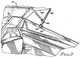
- the system and method of the present invention also contemplates a facile technique for rapidly connecting and disconnecting the boat canopy to a side frame of the windshield, as will now be described with reference to Figures 7, 8 and 9.
- the boat windshield includes a side frame 110, to which the boat canopy is to be rapidly attachable and detachable.
- the boat canopy includes struts 160, 164, with the second strut 164 being attached to the first strut 160 via a plastic fitting 162.
- the first strut 160 is then attached to the side frame 110 utilizing a rapid attach-detach system described in detail with reference to Figure 8.
- the side frame 110 of the windshield comprises an extrusion 116 having various features which are substantially identical to the gripping member 16 described in Figures 1 and 2 above, and which is fitted to the top of the glass forming the side window of the windshield system.
- the extrusion 110 has a pair of arms 18, 20 and an internal plate 124 adapted to fit across the upper extremity of the side windshield with a suitable gasket material therebetween (not shown).
- the extrusion 110 includes an internal plate 126 extending from the plate 124 to a curved plate 128 defining the upper extremity of the extrusion 110.
- the radius of the upper plate 128 is not critical, but is intended to provide a rounded surface 129.
- the extrusion 110 includes an internal recess 130 communicating with a slot 131, the slot extending generally parallel with the side window.
- the extrusion 110 differs from the gripping member 16 of Figures 1 and 2, in that there is provided two additional holes 117, 127 extending through the vertical plates 120, 126 respectively, in order to receive a detent pin 146.
- the detent pin 146 includes a detent ball 148 at one end, and a pull ring 150, and operates in a conventional manner to extend through the holes 131, 127 and 117.
- a plastic fitting 140 having a pair of arms 142, 144 and an internal cavity defining a curved radius 143 that is dimensioned to face against curved surface 129.
- the arm 142 is provided with a hole 143
- arm 144 is provided with a slot hole 145, and with the arms dimensioned such that the holes align with the holes 131, 127 and 117 when the fitting 140 is attached over the side frame extrusion 110, as shown in Figure 8.
- the detent pin 146 holds the plastic fitting 140 and the extrusion 110 together, until the detent pin 146 is removed by pulling the rings 150 to overcome the detent ball 148.
- the fitting 140 includes a slot 152 and a lateral hole 154 extending across the slot 152, and is dimensioned to receive the tongue 157 of a joint member 156, which is preferably plastic and has an internal portion extending into the cylindrical cavity of the first strut 160.
- a fastener 158, 159 extends across the lateral hole 154 and rotatably attaches the joint member 156 with the fitting 140.
- the strut system of the boat canopy is also provided with a similar quick attach-detach system on the opposite side of the boat, and may include similar attach-detach fittings at the stern of the boat as well.
- the struts, including struts 160, 164, of the boat canopy may be rapidly attached and then later rapidly detached from the windshield and side frame assemblies.
- the system, apparatus and method of the present invention thus provides a mechanism for rapidly attaching a canopy or cover to a boat windshield and frame, and which is suitable for use in adverse environmental circumstances.
Landscapes
- Engineering & Computer Science (AREA)
- Mechanical Engineering (AREA)
- Chemical & Material Sciences (AREA)
- Combustion & Propulsion (AREA)
- Ocean & Marine Engineering (AREA)
- Securing Of Glass Panes Or The Like (AREA)
- Window Of Vehicle (AREA)
- Pressure Vessels And Lids Thereof (AREA)
- Re-Forming, After-Treatment, Cutting And Transporting Of Glass Products (AREA)
- Supplying Of Containers To The Packaging Station (AREA)
- Seal Device For Vehicle (AREA)
- Connection Of Plates (AREA)
Abstract
Description
- This invention relates to an arrangement of a boat canopy and a windshield assembly, and more particularly provides an arrangement in which means are provided for rapidly attaching and detaching an end of a strut forming part of the canopy to a side frame of the windshield assembly.
- A variety of techniques have been described in the prior art for attaching a canopy or similar cover to a fixed structure, such as a boat windshield. Typically, metal fastening systems are utilized along the edge of the fixed structure, with mating fasteners on the cover. Examples of such arrangements are shown in the following United States patents: 4,750,449 to Muhlberger; 2,961,725 to McGhie; 2,937,652 to Zimmer et al.; 3,416,282 to Daugherty; 3,093,845 to Brock et al.; 2,961,725 to McGee; 3,021,535 to Dorst; 3,930,738 to Thuss et al.; and 4,993,351 to Zirkelbach et al. Canadian Patent 685,026 is also of interest.
- The present invention provides an improvement in arrangements of a boat canopy and a windshield assembly by providing means for rapidly attaching and detaching an end of a strut which, in use, supports the cover material of the canopy, to a side frame of the windshield assembly.
- In the preferred embodiment of the invention the side frame comprises an extrusion across the top thereof and a lateral hole is provided in the extrusion. The means for rapidly attaching and detaching the end of the strut to the side frame comprises a quick release pin extending through the end of the strut and through the hole in the extrusion. Preferably, a fitting member is secured to the strut, and the pin in use passes through aligned holes in the fitting member and through the extrusion member.
- Various detailed features of the fitting and pin lead to particular advantageous embodiments of the invention.
- The invention also provides a method for rapidly attaching and detaching a boat canopy to and from a windshield assembly wherein the boat canopy comprises a cover of flexible material and at least one strut and the windshield assembly comprises a side frame, the method being characterised by providing an extrusion member attached to a side frame of the windshield assembly, the extrusion member having a slot; providing a fitting associated with the strut of the boat canopy, the fitting having slot members, and rapidly attaching the fitting member to the extrusion member.
- In preferred embodiments of the invention, the flexible material of the cover is secured to the windshield assembly along part of the periphery of the cover by a flexible member which cooperates with a slot provided at the upper edge of the windshield assembly.
- The above and further features and advantages of the invention will become clear from the following description of a preferred embodiment thereof, given by way of example only, reference being had to the accompanying drawings wherein:
- Figure 1 is a cross section of a boat canopy and windshield assembly;
- Figure 2 is a cross section like that of Figure 1 showing an intermediate stage in the locking operation;
- Figure 3 is a cross section like that of Figures 1 and 2 illustrating the boat canopy and windshield assembly in a locking configuration;
- Figure 4 is a cross sectional view like that of Figures 1 - 3 illustrating a step in the unlocking of the flexible member associated with the boat canopy from the gripping member of the boat windshield;
- Figure 5 is a top plan view of the flexible member attached to the inside surface of a boat canopy;
- Figure 6 is an end view of the arrangement shown in Figure 4, during the unlocking operation, with various elements partially cut away;
- Figure 7 is a perspective view of a system in accordance with the present invention for rapidly attaching a boat canopy to a boat windshield assembly, as viewed from the passenger area of an associated boat;
- Figure 8 is a cross sectional elevation of a side frame attachment portion of the system illustrated in Figure 7; and
- Figure 9 is a perspective view of the side frame portions of the attachment system shown in Figures 7 and 8, as viewed from the outside of the associated boat.
-
- A preferred embodiment of the present invention will now be described with reference to the drawings.
- Reference is first made to Figure 1 where a boat windshield and canopy assembly, referred to generally by the
reference numeral 10, is shown. In Figure 1 theassembly 10 includes aboat windshield 12 having an upper extremity 13 and aboat canopy 14 having aninside surface 15. As illustrated, there is provided a grippingmember 16 formed of an extrusion of a suitable material, for example aluminum, having a pair ofarms internal plate 24 adapted to fit across the upper extremity 13 of theboat windshield 12, and along its sides, as shown. Suitably, agasket material 22 is inserted between the grippingmember 16 and theboat windshield 12. Theextrusion 16 includes aninternal plate 26 extending fromplate 24 tocurved plate 28 defining the upper extremity of thegripping member 16. The radius of theupper plate 28 is not critical, but is intended to provide a rounded surface for theboat canopy 14, and its associated flexible member which is described in greater detail below. - With continued referenced to Figure 1, the
gripping member 16 includes aninternal recess 30 communicating with aslot 31, which slot extends generally parallel with the boat windshield. Theslot 31 is defined by the extremities of thearm 18 and the upwardradial plate 28. Theinternal recess 30 is defined by atapered surface 32. - The
flexible member 40 is defined by aflat plate 41, a first portion, orriser 44 extending laterally from theplate 40 and first andsecond locking segments peripheral edge 36 of thecanopy 14 in the embodiment of Figures 1-4. Theplate 40, theriser 44 and the first andsecond locking segments inside surface 15 of thecanopy 14 bythreads 42, adjacent the rolledperiphery 36 of thecanopy 14. - As is shown in Figure 1, the
second locking segment 46 has an insidetapered surface 48 generally conforming to the taper of thesurface 32 along theinternal recess 30 of thegripping member 16. - As is further shown in Figure 1, the
forward locking segment 50 is substantially thinner in cross sectional dimension than the rearwardlocking segment 46, to thereby impart greater flexibility to that forward locking segment. - The configuration of the flexible member, including its
plate 41, the first,riser portion 44 and the rearward andforward locking tabs - Referring again to Figure 1, the
flexible member 40 is locked into thegripping member 16 by first drawing theperipheral edge 36 of theboat canopy 14 downwardly and generally parallel to theboat windshield 12 as is shown by the arrow A in Figure 1. Thereafter, therearward locking segment 46 of theflexible member 40 is pushed through theslot 31 and across thetapered surface 32 of theinternal recess 30 as is shown by the arrow B in Figure 1. After these two steps are accomplished, a portion of the flexible member is within theinternal recess 30 of thegripping member 16, as is illustrated in Figure 2. - The locking procedure is completed in the manner shown in Figure 2, by pushing the
flexible member 40 downwardly as shown by arrow C in Figure 2, to drive the flexible,forward locking segment 50 across the tab 34 and into theinternal recess 30. The resulting configuration is shown in Figure 3, the details of which are described next. As is shown in Figure 3, the insidetapered surface 48 of therearward locking segment 46 lies across the correspondingtapered surface 32 of the gripping member 16 (reference numerals canopy 14 has a significant stretch, thereby keeping theriser portion 44 of theflexible member 40 against the rear edge of theslot 31 as defined by theplate 28. In this configuration, theforward locking segment 50 is maintained in a relationship with tab 34 to just be engaged with that tab, and is not held substantially underneath that tab, as is shown in Figure 3. Such locking as between the tab 34 and thelocking segment 50 is unnecessary, because of the tension of thecanopy 14, and the configured locking arrangement between the tapered surfaces of therearward locking segment 46 and thegripping member 16. - Reference is now made to Figure 4. When it is desired to unlock the
flexible member 40 from thegripping member 16, theperipheral edge 36 of thecanopy 14 is pulled upwardly in a direction away from thearm 18, as is shown by arrow D. As this is undertaken, theforward locking segment 50 easily moves across the extremity of the tab 34. - Reference is now made to Figure 6. As is shown, the
forward locking segment 50 develops a rolled portion 51 as it unlocks from the tab 34. Again, this is achieved because the forward locking segment is both substantially flexible in relation to the rearwardlocking segment 46, and because the forward locking segment does not extend substantially underneath the tab 34 of thegripping member 16. - The system and method of the present invention also contemplates a facile technique for rapidly connecting and disconnecting the boat canopy to a side frame of the windshield, as will now be described with reference to Figures 7, 8 and 9.
- Noting Figure 7, the boat windshield includes a
side frame 110, to which the boat canopy is to be rapidly attachable and detachable. Conventionally, the boat canopy includesstruts 160, 164, with the second strut 164 being attached to thefirst strut 160 via aplastic fitting 162. Thefirst strut 160 is then attached to theside frame 110 utilizing a rapid attach-detach system described in detail with reference to Figure 8. - The
side frame 110 of the windshield comprises an extrusion 116 having various features which are substantially identical to thegripping member 16 described in Figures 1 and 2 above, and which is fitted to the top of the glass forming the side window of the windshield system. In Figure 8, theextrusion 110 has a pair ofarms extrusion 110 includes aninternal plate 126 extending from the plate 124 to acurved plate 128 defining the upper extremity of theextrusion 110. The radius of theupper plate 128 is not critical, but is intended to provide arounded surface 129. Theextrusion 110 includes an internal recess 130 communicating with aslot 131, the slot extending generally parallel with the side window. Theextrusion 110 differs from thegripping member 16 of Figures 1 and 2, in that there is provided two additional holes 117, 127 extending through thevertical plates detent pin 146. Thedetent pin 146 includes adetent ball 148 at one end, and apull ring 150, and operates in a conventional manner to extend through theholes 131, 127 and 117. - In order to rapidly attach and detach the
first strut 160 to theside frame extrusion 110, there is provided aplastic fitting 140 having a pair ofarms curved radius 143 that is dimensioned to face againstcurved surface 129. Thearm 142 is provided with ahole 143, andarm 144 is provided with aslot hole 145, and with the arms dimensioned such that the holes align with theholes 131, 127 and 117 when thefitting 140 is attached over theside frame extrusion 110, as shown in Figure 8. In this manner, thedetent pin 146 holds the plastic fitting 140 and theextrusion 110 together, until thedetent pin 146 is removed by pulling therings 150 to overcome thedetent ball 148. - The
fitting 140 includes aslot 152 and a lateral hole 154 extending across theslot 152, and is dimensioned to receive the tongue 157 of ajoint member 156, which is preferably plastic and has an internal portion extending into the cylindrical cavity of thefirst strut 160. Afastener joint member 156 with the fitting 140. - It will be appreciated by those skilled in the art that the strut system of the boat canopy is also provided with a similar quick attach-detach system on the opposite side of the boat, and may include similar attach-detach fittings at the stern of the boat as well. In this manner, the struts, including
struts 160, 164, of the boat canopy may be rapidly attached and then later rapidly detached from the windshield and side frame assemblies. - The system, apparatus and method of the present invention thus provides a mechanism for rapidly attaching a canopy or cover to a boat windshield and frame, and which is suitable for use in adverse environmental circumstances.
- This concludes the description of the preferred embodiments. A reading by those skilled in the art will bring to mind various changes without departing from the spirit and scope of the invention. It is intended, however, that the invention only be limited by the following appended claims.
- The instant invention has been shown and described herein in what is considered to be the most practical and preferred embodiment. It is recognized, however, that departures may be made therefrom within the scope of the invention and that obvious modifications will occur to a person skilled in the art.
Claims (10)
- An arrangement of a boat canopy (14) and a windshield assembly (12), wherein the boat canopy (14) includes a cover of flexible material and at least one strut (160) for supporting the cover in a use configuration and wherein the windshield assembly (12) includes a side frame (110), characterised in that means are provided for rapidly attaching and detaching an end of the strut (160) to the side frame (110).
- An arrangement according to claim 1, characterised in that the windshield side frame (110) comprises an extrusion (116) across the top thereof, a lateral hole (127) is provided in the extrusion, and the means for rapidly attaching and detaching the strut to the side frame comprises a quick release pin (146) removably extending through the end of the strut (160) and through the hole (127) in the extrusion (116).
- An arrangement according to claim 2, characterised in that a lateral slot (131) extends through the extrusion (116) and the quick release pin (146) removably extends through the slot (131).
- An arrangement according to claim 1, characterised in that the means for rapidly attaching and detaching an end of said at least one strut (160) to the side frame (110) comprises a lateral slot (131) in the side frame (110) and a quick release pin member (146) extending through said lateral slot (131) so as to directly or indirectly engage said strut end.
- An arrangement according to claim 4, characterised in that the side frame (110) comprises an extrusion member (116) through which the lateral slot (131) extends.
- An arrangement according to claim 3 or claim 5, characterised in that: a fitting member (140) is provided comprising a top end and a bottom end, one or more struts of said canopy (14) being associated with said top end and slot members (143,145) being disposed at said bottom end; said slot members (143,145) of said fitting member (140) are aligned with said slot (131) of said extrusion member when attaching said fitting member (140) to said extrusion member; and said pin member (146) is received within said slot members (143,145) of said fitting member (140) and said slot (131) of said extrusion member when attaching said fitting member (140) to said extrusion member.
- An arrangement according to claim 3 or claim 6, characterised in that said pin member (146) has a detent ball (148) at one end and a pull ring (150) at an opposite end.
- An arrangement according to claim 6, characterised in that a joint member (156) is attached at a bottom end thereof to said fitting member (140) and associated with one of said one or more canopy struts at its top end.
- An arrangement according to claim 8, characterised in that said joint member (156) is rotatably attached to said fitting member (140).
- A method for rapidly attaching and detaching a boat canopy (14) and windshield assembly, comprising the steps of: providing an extrusion member attached to a side frame (110) of the boat windshield assembly, said extrusion member having a slot (131); providing a fitting member (140), said fitting member (140) associated with one or more struts of the boat canopy (14) and having slot members (143,145); and rapidly attaching said fitting member (140) to said extrusion member.
Applications Claiming Priority (3)
| Application Number | Priority Date | Filing Date | Title |
|---|---|---|---|
| US08/068,441 US5367977A (en) | 1991-11-19 | 1993-05-27 | System, apparatus and method for rapidly attaching a boat cover or canopy to a windshield and frame |
| US68441 | 1993-05-27 | ||
| EP94918027A EP0651711B1 (en) | 1993-05-27 | 1994-05-18 | Apparatus and method for attaching a canopy |
Related Parent Applications (2)
| Application Number | Title | Priority Date | Filing Date |
|---|---|---|---|
| EP94918027A Division-Into EP0651711B1 (en) | 1993-05-27 | 1994-05-18 | Apparatus and method for attaching a canopy |
| EP94918027A Division EP0651711B1 (en) | 1993-05-27 | 1994-05-18 | Apparatus and method for attaching a canopy |
Publications (3)
| Publication Number | Publication Date |
|---|---|
| EP0940335A2 true EP0940335A2 (en) | 1999-09-08 |
| EP0940335A3 EP0940335A3 (en) | 1999-09-29 |
| EP0940335B1 EP0940335B1 (en) | 2004-07-14 |
Family
ID=22082606
Family Applications (2)
| Application Number | Title | Priority Date | Filing Date |
|---|---|---|---|
| EP99202041A Expired - Lifetime EP0940335B1 (en) | 1993-05-27 | 1994-05-18 | Arrangement of a boat canopy and windshield assembly |
| EP94918027A Expired - Lifetime EP0651711B1 (en) | 1993-05-27 | 1994-05-18 | Apparatus and method for attaching a canopy |
Family Applications After (1)
| Application Number | Title | Priority Date | Filing Date |
|---|---|---|---|
| EP94918027A Expired - Lifetime EP0651711B1 (en) | 1993-05-27 | 1994-05-18 | Apparatus and method for attaching a canopy |
Country Status (6)
| Country | Link |
|---|---|
| US (1) | US5367977A (en) |
| EP (2) | EP0940335B1 (en) |
| AT (2) | ATE270998T1 (en) |
| DE (2) | DE69433904T2 (en) |
| ES (2) | ES2224544T3 (en) |
| WO (1) | WO1994027863A1 (en) |
Families Citing this family (29)
| Publication number | Priority date | Publication date | Assignee | Title |
|---|---|---|---|---|
| US5425327A (en) * | 1992-07-15 | 1995-06-20 | Aldon Industries, Inc. | Boat canopy mounting system |
| US5702147A (en) * | 1995-05-09 | 1997-12-30 | Bestop, Inc. | Tailgate sealing arrangement |
| US6241305B1 (en) | 1996-05-08 | 2001-06-05 | Bestop, Inc. | Removable retainer arrangements for flexible, vehicle tops |
| US6026761A (en) * | 1997-01-31 | 2000-02-22 | Taylor Made Systems Bradenton, Inc. | Canopy mounting system |
| US6158377A (en) * | 1999-08-06 | 2000-12-12 | Szukhent, Jr.; Steve | Knock-down canopy |
| US6453841B1 (en) | 2000-12-21 | 2002-09-24 | Nelson A. Taylor Co., Inc. | Windshield bottom trim |
| US6800160B2 (en) * | 2001-06-12 | 2004-10-05 | Water Bonnet Manufacturing, Inc. | Stress-free mounting system for sheet material |
| US6647915B1 (en) * | 2002-06-20 | 2003-11-18 | Malibu Boats West, Inc. | Windshield edge assembly and method |
| US6672241B2 (en) | 2002-07-12 | 2004-01-06 | Bennington Marine, Inc. | Foldable frame for a boat cover |
| US7159530B1 (en) | 2002-08-14 | 2007-01-09 | Taylor Made Group, Inc. | Convertible boat top |
| US7096816B2 (en) * | 2003-10-27 | 2006-08-29 | Ameritex Technologies, Inc | Boat windshield canvas attachment apparatus |
| US7222580B2 (en) * | 2003-10-27 | 2007-05-29 | Taylor Made Group, Inc. | Enclosure incorporating adjustable releasable fastener |
| US8028640B2 (en) * | 2004-04-12 | 2011-10-04 | Xtreme Seal, Llc | Compositions and methods for sealing |
| US20060014176A1 (en) * | 2004-05-26 | 2006-01-19 | Iyer Radhakrishnan P | Reactor for chemical synthesis |
| US7143717B2 (en) * | 2004-10-27 | 2006-12-05 | Murphy Mark J | Cover attachment system |
| US7107926B2 (en) | 2004-10-29 | 2006-09-19 | Bennington Marine, Llc | Bimini top main bow connector |
| US7281485B1 (en) | 2005-06-16 | 2007-10-16 | Bach Darren A | Windshield trim assembly and method |
| US7503275B2 (en) * | 2005-09-30 | 2009-03-17 | Ameritex Technologies, Inc. | System for attaching a flexible enclosure to a boat windshield frame |
| US7806069B2 (en) * | 2008-08-11 | 2010-10-05 | Taylor Made Group, Llc | System for attaching a flexible cover and an edge clip for the same |
| US8056495B2 (en) * | 2008-08-29 | 2011-11-15 | Lemons Daniel E | Pontoon bimini extender and rail clamping mechanism |
| US9045022B2 (en) * | 2013-01-24 | 2015-06-02 | Stephen Tyrer | Golf cart enclosure and system and method of attaching enclosure to golf cart |
| US10300833B2 (en) * | 2014-01-29 | 2019-05-28 | Dowco, Inc. | Resilient cover clip |
| US9759373B2 (en) * | 2014-08-07 | 2017-09-12 | Dowco, Inc. | Fabric attachment system |
| US20180141619A1 (en) * | 2016-11-21 | 2018-05-24 | DTS Enterprises, Inc. | Cover latch and locking system |
| US10793228B2 (en) | 2016-12-02 | 2020-10-06 | Polaris Industries Inc. | Structure and assembly for recessed deck portion in pontoon boat |
| US10472022B1 (en) | 2018-10-17 | 2019-11-12 | Randall Paul Pollen | Releasable Bimini top |
| US11192610B2 (en) | 2019-10-30 | 2021-12-07 | Polaris Industies Inc. | Multiple chine pontoon boat |
| US11400798B2 (en) * | 2019-11-21 | 2022-08-02 | Taylor Made Group, Llc | Windshield quick attach and release system |
| AT18193U1 (en) * | 2022-10-14 | 2024-04-15 | Plasser & Theurer Export Von Bahnbaumaschinen Gmbh | Sealing device for sealingly connecting a first body to a second body, in particular for a track construction device, and device |
Citations (9)
| Publication number | Priority date | Publication date | Assignee | Title |
|---|---|---|---|---|
| US2937652A (en) | 1958-09-08 | 1960-05-24 | Nelson A Taylor Co Inc | Means for detachably fastening a flexible top to a windshield |
| US2961725A (en) | 1959-04-16 | 1960-11-29 | Mcgee Richard | Fastening device |
| US3021535A (en) | 1959-12-07 | 1962-02-20 | Textron Inc | Swing-over windshield for motorboats |
| US3093845A (en) | 1961-03-28 | 1963-06-18 | Standard Products Co | Windshield structure |
| CA685026A (en) | 1962-09-05 | 1964-04-21 | Dagenais Guy | Windshield rim molding |
| US3416282A (en) | 1966-06-16 | 1968-12-17 | Cardinal Extrusions Co | Elongate panel edging strip of the prefabricated type |
| US3930738A (en) | 1974-11-05 | 1976-01-06 | Swiss Aluminium Ltd. | Adjustable window frame anchor clip |
| US4750449A (en) | 1987-01-30 | 1988-06-14 | N. A. Taylor Co., Inc. | Curved windshield mounting system |
| US4993351A (en) | 1989-09-19 | 1991-02-19 | Aldon Industries, Inc. | Rounded top header extrusion for boat windshields |
Family Cites Families (10)
| Publication number | Priority date | Publication date | Assignee | Title |
|---|---|---|---|---|
| US2829660A (en) * | 1956-01-03 | 1958-04-08 | Charles W Wester | Canopy |
| US3172419A (en) * | 1963-01-31 | 1965-03-09 | Lone Star Boat Company | Canopy lock for boats |
| US3510998A (en) * | 1966-03-02 | 1970-05-12 | Gentex Corp | Readily adjustable arch support for boat canopy |
| FR1533359A (en) * | 1967-06-06 | 1968-07-19 | Convertible automobile | |
| US4926782A (en) * | 1988-08-26 | 1990-05-22 | Lacy Franklin R | Adjustable windshield and canopy for a boat |
| NO165952C (en) * | 1989-01-16 | 1991-05-15 | Products & Marketing A S | DEVICE AT CALACE STAND. |
| US4979457A (en) * | 1989-09-08 | 1990-12-25 | Peter M. Sommerhauser | Support apparatus for a protective covering and the like |
| US5056855A (en) * | 1990-08-10 | 1991-10-15 | Andrew Moravsky | Vehicle bed cover assembly |
| US5215032A (en) * | 1991-11-19 | 1993-06-01 | Ray Industries, Inc. | System, apparatus and method for rapidly attaching a boat cover or canopy to a windshield |
| US5238288A (en) * | 1992-06-15 | 1993-08-24 | Chandler M Robert | Pick-up truck bed collapsible cover |
-
1993
- 1993-05-27 US US08/068,441 patent/US5367977A/en not_active Expired - Fee Related
-
1994
- 1994-05-18 ES ES99202041T patent/ES2224544T3/en not_active Expired - Lifetime
- 1994-05-18 EP EP99202041A patent/EP0940335B1/en not_active Expired - Lifetime
- 1994-05-18 AT AT99202041T patent/ATE270998T1/en not_active IP Right Cessation
- 1994-05-18 WO PCT/US1994/005555 patent/WO1994027863A1/en active IP Right Grant
- 1994-05-18 AT AT94918027T patent/ATE191410T1/en not_active IP Right Cessation
- 1994-05-18 DE DE69433904T patent/DE69433904T2/en not_active Expired - Fee Related
- 1994-05-18 DE DE69423844T patent/DE69423844T2/en not_active Expired - Fee Related
- 1994-05-18 EP EP94918027A patent/EP0651711B1/en not_active Expired - Lifetime
- 1994-05-18 ES ES94918027T patent/ES2147575T3/en not_active Expired - Lifetime
Patent Citations (9)
| Publication number | Priority date | Publication date | Assignee | Title |
|---|---|---|---|---|
| US2937652A (en) | 1958-09-08 | 1960-05-24 | Nelson A Taylor Co Inc | Means for detachably fastening a flexible top to a windshield |
| US2961725A (en) | 1959-04-16 | 1960-11-29 | Mcgee Richard | Fastening device |
| US3021535A (en) | 1959-12-07 | 1962-02-20 | Textron Inc | Swing-over windshield for motorboats |
| US3093845A (en) | 1961-03-28 | 1963-06-18 | Standard Products Co | Windshield structure |
| CA685026A (en) | 1962-09-05 | 1964-04-21 | Dagenais Guy | Windshield rim molding |
| US3416282A (en) | 1966-06-16 | 1968-12-17 | Cardinal Extrusions Co | Elongate panel edging strip of the prefabricated type |
| US3930738A (en) | 1974-11-05 | 1976-01-06 | Swiss Aluminium Ltd. | Adjustable window frame anchor clip |
| US4750449A (en) | 1987-01-30 | 1988-06-14 | N. A. Taylor Co., Inc. | Curved windshield mounting system |
| US4993351A (en) | 1989-09-19 | 1991-02-19 | Aldon Industries, Inc. | Rounded top header extrusion for boat windshields |
Also Published As
| Publication number | Publication date |
|---|---|
| DE69423844T2 (en) | 2001-02-15 |
| EP0651711B1 (en) | 2000-04-05 |
| DE69433904T2 (en) | 2004-12-16 |
| ES2147575T3 (en) | 2000-09-16 |
| WO1994027863A1 (en) | 1994-12-08 |
| DE69433904D1 (en) | 2004-08-19 |
| ATE191410T1 (en) | 2000-04-15 |
| ES2224544T3 (en) | 2005-03-01 |
| EP0651711A4 (en) | 1996-02-14 |
| ATE270998T1 (en) | 2004-07-15 |
| EP0651711A1 (en) | 1995-05-10 |
| EP0940335B1 (en) | 2004-07-14 |
| EP0940335A3 (en) | 1999-09-29 |
| DE69423844D1 (en) | 2000-05-11 |
| US5367977A (en) | 1994-11-29 |
Similar Documents
| Publication | Publication Date | Title |
|---|---|---|
| EP0940335A2 (en) | Arrangement of a boat canopy and windshield assembly | |
| US5215032A (en) | System, apparatus and method for rapidly attaching a boat cover or canopy to a windshield | |
| DE10022789B4 (en) | Child seat | |
| US20020109371A1 (en) | Pivoting rail having tonneau cover system | |
| US20060107485A1 (en) | End clip of vehicle wiper blade | |
| US6536084B2 (en) | Low profile integrated omega zipper closure system | |
| CN108688814A (en) | Connector | |
| US20050258623A1 (en) | Airbag module removal structure | |
| US5425327A (en) | Boat canopy mounting system | |
| EP1348621A2 (en) | Window attachment system and method | |
| US4278284A (en) | Arrangement for suspending a pivoted side-board | |
| US6212802B1 (en) | Display apparatus | |
| US20080044608A1 (en) | Method for Making an Interior Covering Element, and Interior Covering Element with no Central Defect | |
| US4512598A (en) | Releasable latch bracket means for a vehicle sunroof | |
| US20210300177A1 (en) | Canister Mounting Structure | |
| EP1362728A1 (en) | Side-Visor support assembly | |
| DE29823838U1 (en) | Device for fastening a tank bag, adapter plate and tank bag | |
| GB2306635A (en) | Mounting vehicle lamps | |
| US7096816B2 (en) | Boat windshield canvas attachment apparatus | |
| EP0239185B1 (en) | Magnetic mounting means | |
| CN218021515U (en) | Ring sleeve buckle structure | |
| CN213833383U (en) | Material conveying guide rail supporting and adjusting frame | |
| CN112623048B (en) | Compromise manual brake access cover plate structure of saucer | |
| US6173873B1 (en) | Arrangement for holding a suitcase on a motor vehicle hood | |
| CN218702508U (en) | Rim assembly of vehicle and vehicle |
Legal Events
| Date | Code | Title | Description |
|---|---|---|---|
| PUAI | Public reference made under article 153(3) epc to a published international application that has entered the european phase |
Free format text: ORIGINAL CODE: 0009012 |
|
| PUAL | Search report despatched |
Free format text: ORIGINAL CODE: 0009013 |
|
| 17P | Request for examination filed |
Effective date: 19990705 |
|
| AC | Divisional application: reference to earlier application |
Ref document number: 651711 Country of ref document: EP |
|
| AK | Designated contracting states |
Kind code of ref document: A2 Designated state(s): AT BE CH DE DK ES FR GB GR IE IT LI LU MC NL PT SE |
|
| AK | Designated contracting states |
Kind code of ref document: A3 Designated state(s): AT BE CH DE DK ES FR GB GR IE IT LI LU MC NL PT SE |
|
| 17Q | First examination report despatched |
Effective date: 20021219 |
|
| GRAP | Despatch of communication of intention to grant a patent |
Free format text: ORIGINAL CODE: EPIDOSNIGR1 |
|
| GRAS | Grant fee paid |
Free format text: ORIGINAL CODE: EPIDOSNIGR3 |
|
| GRAA | (expected) grant |
Free format text: ORIGINAL CODE: 0009210 |
|
| RAP1 | Party data changed (applicant data changed or rights of an application transferred) |
Owner name: BRUNSWICK CORPORATION |
|
| AC | Divisional application: reference to earlier application |
Ref document number: 0651711 Country of ref document: EP Kind code of ref document: P |
|
| AK | Designated contracting states |
Kind code of ref document: B1 Designated state(s): AT BE CH DE DK ES FR GB GR IE IT LI LU MC NL PT SE |
|
| PG25 | Lapsed in a contracting state [announced via postgrant information from national office to epo] |
Ref country code: NL Free format text: LAPSE BECAUSE OF FAILURE TO SUBMIT A TRANSLATION OF THE DESCRIPTION OR TO PAY THE FEE WITHIN THE PRESCRIBED TIME-LIMIT Effective date: 20040714 Ref country code: LI Free format text: LAPSE BECAUSE OF FAILURE TO SUBMIT A TRANSLATION OF THE DESCRIPTION OR TO PAY THE FEE WITHIN THE PRESCRIBED TIME-LIMIT Effective date: 20040714 Ref country code: CH Free format text: LAPSE BECAUSE OF FAILURE TO SUBMIT A TRANSLATION OF THE DESCRIPTION OR TO PAY THE FEE WITHIN THE PRESCRIBED TIME-LIMIT Effective date: 20040714 Ref country code: BE Free format text: LAPSE BECAUSE OF FAILURE TO SUBMIT A TRANSLATION OF THE DESCRIPTION OR TO PAY THE FEE WITHIN THE PRESCRIBED TIME-LIMIT Effective date: 20040714 Ref country code: AT Free format text: LAPSE BECAUSE OF FAILURE TO SUBMIT A TRANSLATION OF THE DESCRIPTION OR TO PAY THE FEE WITHIN THE PRESCRIBED TIME-LIMIT Effective date: 20040714 |
|
| REG | Reference to a national code |
Ref country code: GB Ref legal event code: FG4D |
|
| REG | Reference to a national code |
Ref country code: CH Ref legal event code: EP |
|
| REF | Corresponds to: |
Ref document number: 69433904 Country of ref document: DE Date of ref document: 20040819 Kind code of ref document: P |
|
| REG | Reference to a national code |
Ref country code: IE Ref legal event code: FG4D |
|
| PG25 | Lapsed in a contracting state [announced via postgrant information from national office to epo] |
Ref country code: SE Free format text: LAPSE BECAUSE OF FAILURE TO SUBMIT A TRANSLATION OF THE DESCRIPTION OR TO PAY THE FEE WITHIN THE PRESCRIBED TIME-LIMIT Effective date: 20041014 Ref country code: GR Free format text: LAPSE BECAUSE OF FAILURE TO SUBMIT A TRANSLATION OF THE DESCRIPTION OR TO PAY THE FEE WITHIN THE PRESCRIBED TIME-LIMIT Effective date: 20041014 Ref country code: DK Free format text: LAPSE BECAUSE OF FAILURE TO SUBMIT A TRANSLATION OF THE DESCRIPTION OR TO PAY THE FEE WITHIN THE PRESCRIBED TIME-LIMIT Effective date: 20041014 |
|
| NLV1 | Nl: lapsed or annulled due to failure to fulfill the requirements of art. 29p and 29m of the patents act | ||
| REG | Reference to a national code |
Ref country code: CH Ref legal event code: PL |
|
| REG | Reference to a national code |
Ref country code: ES Ref legal event code: FG2A Ref document number: 2224544 Country of ref document: ES Kind code of ref document: T3 |
|
| ET | Fr: translation filed | ||
| PG25 | Lapsed in a contracting state [announced via postgrant information from national office to epo] |
Ref country code: LU Free format text: LAPSE BECAUSE OF NON-PAYMENT OF DUE FEES Effective date: 20050518 Ref country code: IT Free format text: LAPSE BECAUSE OF NON-PAYMENT OF DUE FEES Effective date: 20050518 Ref country code: GB Free format text: LAPSE BECAUSE OF NON-PAYMENT OF DUE FEES Effective date: 20050518 |
|
| PG25 | Lapsed in a contracting state [announced via postgrant information from national office to epo] |
Ref country code: ES Free format text: LAPSE BECAUSE OF NON-PAYMENT OF DUE FEES Effective date: 20050519 |
|
| PLBE | No opposition filed within time limit |
Free format text: ORIGINAL CODE: 0009261 |
|
| STAA | Information on the status of an ep patent application or granted ep patent |
Free format text: STATUS: NO OPPOSITION FILED WITHIN TIME LIMIT |
|
| PG25 | Lapsed in a contracting state [announced via postgrant information from national office to epo] |
Ref country code: MC Free format text: LAPSE BECAUSE OF NON-PAYMENT OF DUE FEES Effective date: 20050531 |
|
| 26N | No opposition filed |
Effective date: 20050415 |
|
| PG25 | Lapsed in a contracting state [announced via postgrant information from national office to epo] |
Ref country code: DE Free format text: LAPSE BECAUSE OF NON-PAYMENT OF DUE FEES Effective date: 20051201 |
|
| GBPC | Gb: european patent ceased through non-payment of renewal fee |
Effective date: 20050518 |
|
| PG25 | Lapsed in a contracting state [announced via postgrant information from national office to epo] |
Ref country code: FR Free format text: LAPSE BECAUSE OF NON-PAYMENT OF DUE FEES Effective date: 20060131 |
|
| REG | Reference to a national code |
Ref country code: IE Ref legal event code: MM4A |
|
| REG | Reference to a national code |
Ref country code: FR Ref legal event code: ST Effective date: 20060131 |
|
| REG | Reference to a national code |
Ref country code: ES Ref legal event code: FD2A Effective date: 20050519 |
|
| PG25 | Lapsed in a contracting state [announced via postgrant information from national office to epo] |
Ref country code: PT Free format text: LAPSE BECAUSE OF NON-PAYMENT OF DUE FEES Effective date: 20041214 |