EP0940275A1 - Air conditioning unit - Google Patents
Air conditioning unit Download PDFInfo
- Publication number
- EP0940275A1 EP0940275A1 EP99300041A EP99300041A EP0940275A1 EP 0940275 A1 EP0940275 A1 EP 0940275A1 EP 99300041 A EP99300041 A EP 99300041A EP 99300041 A EP99300041 A EP 99300041A EP 0940275 A1 EP0940275 A1 EP 0940275A1
- Authority
- EP
- European Patent Office
- Prior art keywords
- conditioning unit
- air conditioning
- air
- steering beam
- upper outlet
- Prior art date
- Legal status (The legal status is an assumption and is not a legal conclusion. Google has not performed a legal analysis and makes no representation as to the accuracy of the status listed.)
- Granted
Links
Images


Classifications
-
- B—PERFORMING OPERATIONS; TRANSPORTING
- B60—VEHICLES IN GENERAL
- B60H—ARRANGEMENTS OF HEATING, COOLING, VENTILATING OR OTHER AIR-TREATING DEVICES SPECIALLY ADAPTED FOR PASSENGER OR GOODS SPACES OF VEHICLES
- B60H1/00—Heating, cooling or ventilating devices
- B60H1/00007—Combined heating, ventilating, or cooling devices
- B60H1/00021—Air flow details of HVAC devices
- B60H1/00028—Constructional lay-out of the devices in the vehicle
-
- B—PERFORMING OPERATIONS; TRANSPORTING
- B60—VEHICLES IN GENERAL
- B60H—ARRANGEMENTS OF HEATING, COOLING, VENTILATING OR OTHER AIR-TREATING DEVICES SPECIALLY ADAPTED FOR PASSENGER OR GOODS SPACES OF VEHICLES
- B60H1/00—Heating, cooling or ventilating devices
- B60H1/00507—Details, e.g. mounting arrangements, desaeration devices
- B60H1/00514—Details of air conditioning housings
-
- B—PERFORMING OPERATIONS; TRANSPORTING
- B60—VEHICLES IN GENERAL
- B60H—ARRANGEMENTS OF HEATING, COOLING, VENTILATING OR OTHER AIR-TREATING DEVICES SPECIALLY ADAPTED FOR PASSENGER OR GOODS SPACES OF VEHICLES
- B60H1/00—Heating, cooling or ventilating devices
- B60H1/00007—Combined heating, ventilating, or cooling devices
- B60H1/00021—Air flow details of HVAC devices
- B60H2001/00078—Assembling, manufacturing or layout details
- B60H2001/00107—Assembling, manufacturing or layout details characterised by the relative position of the heat exchangers, e.g. arrangements leading to a curved airflow
-
- B—PERFORMING OPERATIONS; TRANSPORTING
- B60—VEHICLES IN GENERAL
- B60H—ARRANGEMENTS OF HEATING, COOLING, VENTILATING OR OTHER AIR-TREATING DEVICES SPECIALLY ADAPTED FOR PASSENGER OR GOODS SPACES OF VEHICLES
- B60H1/00—Heating, cooling or ventilating devices
- B60H1/00007—Combined heating, ventilating, or cooling devices
- B60H1/00207—Combined heating, ventilating, or cooling devices characterised by the position of the HVAC devices with respect to the passenger compartment
- B60H2001/00214—Devices in front of the passenger compartment
Definitions
- the present invention relates to an air conditioning unit mounted in a vehicle and, in particular, in a vehicle without a hood such as a van, a delivery wagon or the like, which is provided in front of the steering beam and is structured to prevent damage to and deformation of the steering beam in the event of a collision.
- Japanese Unexamined Utility Model Publication No.H4-28105 discloses an air conditioning unit structured to be adopted in a vehicle in which it is positioned in front of a steering support member (steering beam) in the body and is provided with a means for movement that moves the air conditioning unit toward the lower portion of the body in the event of a collision.
- a collision occurs, the portion of the air conditioning unit that supports the upper rear portion of the vehicle becomes disengaged so that it is caused to artificially move downward or is caused to naturally fall downward, with the lower front portion of the vehicle air conditioning unit working as the fulcrum.
- Japanese Unexamined Utility Model Publication No. H4-104076 discloses a structure in which the steering beam is constituted of a sheet metal member and a knife-edge portion is provided in close proximity to and facing opposite the rear surface of an air conditioning unit case provided in front of the steering beam.
- the publication of the second example also discloses that a vulnerable portion constituted of a reduced thickness portion or the like is provided in the vicinity of the rear surface which faces opposite the knife-edge portion in close proximity.
- Japanese Unexamined Patent Publication No.H8- 192639 discloses a structure provided with an energy absorbing portion that absorbs collision energy through deformation by forming a notched portion at the front portion of an electric car so that it bends in an upward projection as compression deformation occurs when a compression load is applied and an energy absorbing portion that absorbs collision energy through deformation is provided.
- the publication of the third example discloses that an energy absorbing portion is also provided at a storage case for the fuel cell by forming a notched portion and a groove.
- the first example presents problems in the event of a collision in that when the collision speed is high, the speed at which the air conditioning system drops may not be high enough with respect to the collision speed and in that the air conditioning system itself may not be fully secured in place.
- the second example presents a problem in that the structure of the steering beam is special and there is a problem with the third example in that the strength of the car body itself is reduced.
- an object of the present invention is to provide an air conditioning unit having a structure that prevents, with a high degree of reliability, deformation of and damage to the steering beam caused by the air conditioning unit in the event of a collision.
- the air conditioning unit according to the present invention which is mounted in front of the steering beam in the body of the vehicle, comprises an air conditioner case that defines a roughly U-shaped airflow path, an air intake portion located at the upstream side of the airflow path, in which an air blower is provided, an upper outlet portion located to the rear of the air intake portion in the direction in which the vehicle advances and positioned at a downstream side of the airflow path, a means for temperature control provided in the airflow path downstream of the air intake portion, a lower outlet portion located in the vicinity of and downstream of the means for temperature control and positioned at another downstream side of the airflow path and an outlet mode door that selectively opens the upper outlet portion and the lower outlet portion, a stress concentrating structure that lowers the dynamic strength of the air conditioning unit in the
- the stress concentrating structure that lowers the dynamic strength of the air conditioning unit relative to the deformation load of the steering beam is formed in a portion of the air conditioning unit that is located within the range over which the steering beam is projected and the air intake portion where the air blower is provided is positioned lower than the range over which the steering beam is projected, the air conditioning unit is destroyed before the deformation of the steering beam occurs.
- the air intake portion where the air blower is provided which has a high degree of dynamic strength, is not within the range over which the steering beam is projected, the air conditioning unit can be destroyed at a load which is smaller than the deformation load of the steering beam. Consequently, deformation of and damage to the steering beam can be prevented.
- the upper outlet portion is provided with at least one opening that opens upward and a flange portion around the opening.
- the stress concentrating structure is constituted of at least one cut portion formed on a side constituting the flange portion along the direction of impact.
- the side on which at least one cut portion is formed as described above may be formed in an arch that distends in a direction vertical to the direction of impact. This will concentrate the stress occurring during a collision in the cut portion with a high degree of efficiency.
- the stress concentrating structure may be preferably constituted of a groove formed at a side surface of the upper outlet portion along the direction of impact, since this will cause the side surface to break easily so that the upper outlet portion becomes deformed easily.
- the stress concentrating structure may be constituted of a pair of ribs that are formed at a side surface of the upper outlet portion along the direction of impact instead. This will cause the stress to concentrate between the pair of ribs readily so that the side surface becomes deformed easily.
- the air conditioner case may be constituted of a pair of case assembly parts each having a bonding portion along the airflow path with the stress concentrating structure constituted of a notched portion formed in a part of the bonding portion of the case assembly parts that constitute the upper outlet portion. Since the ribs cause the bonding portions constituting the upper outlet portion to break easily, deformation of or damage to the upper outlet portion can be induced early.
- FIG. 1 is a side elevation schematically illustrating a side surface of the air conditioning unit in an embodiment of the present invention in a mounted state
- FIG. 2 is a front view of the air conditioning unit above, schematically illustrating the front of the unit viewed from the inside of the vehicle cabin
- FIG. 3 is a front view of the air conditioning unit above, schematically illustrating the other side surface
- FIG. 4 is a cross section illustrating the internal structure of the air conditioning unit above
- FIG. 5 is a perspective illustrating the vicinity of the upper outlet portion of the air conditioning unit above in a partial enlargements
- FIG. 6 is a side elevation illustrating the vicinity of the upper outlet portion of the air conditioning unit in another embodiment in a partial enlargement
- FIG. 1 is a side elevation schematically illustrating a side surface of the air conditioning unit in an embodiment of the present invention in a mounted state
- FIG. 2 is a front view of the air conditioning unit above, schematically illustrating the front of the unit viewed from the inside of the vehicle cabin
- FIG. 7 is a cross section illustrating a first embodiment of the stress concentrating groove in a partial enlargement
- FIG. 8 is a cross section illustrating a second embodiment of the stress concentrating groove in a partial enlargement
- FIG. 9 is a cross section illustrating a third embodiment of the stress concentrating groove in a partial enlargement
- FIG. 10 is a plan view illustrating another embodiment of the flange portion at the upper outlet portion in a partial enlargement
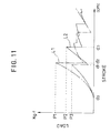
- FIG. 11 is a characteristics diagram presenting the test results that indicate the relationship between the range of movement of the steering beam 4 and the load in an air conditioning unit without a stress concentrating structure and in an air conditioning unit provided with a stress concentrating structure.
- An air conditioning unit 1 illustrated in FIGS. 1 through 4 which is designed to achieve a high degree of compactness so that it can be installed in a vehicle and, in particular, in a vehicle without a hood such as a van, a delivery wagon or the like, is provided between a front panel 2 of the vehicle and a steering beam 4 at a car body which is provided vertically to the direction in which the vehicle advances, and within an instrument panel 3, i.e., between the central line A of the vehicle in FIG. 2 and the front passenger seat.
- the air conditioning unit 1 comprises an intake unit 5 and a temperature control unit 6.
- the intake unit 5 is provided with an internal air induction portion 7 and an external air induction portion 8, with an intake door (not shown) that selectively opens the internal air induction portion 7 and the external air induction portion 8 as necessary provided between them.
- reference number 9 indicates an arm which is linked to the intake door
- reference number 10 indicates a drive arm for moving the arm 9
- reference number 11 is a terminal at which a wire cable wired to move the drive arm from the outside is secured.
- reference number 12 indicates a fixing terminal for fixing the wire cable.
- a filter mounting portion 13 is provided at the intake unit 5 in this embodiment so that an electric dust collector, a filter or the like can be mounted internally. Furthermore, the intake unit 5 is mounted and secured at an air intake portion 14 of the temperature control unit 6.
- the temperature control unit 6 is constituted of an air conditioner case comprising, at least, three case members (a first case member, a second case member and a third case member) 15a, 15b and 15c, the air intake portion 14 provided in the upper portion of the air conditioner case 15, an upper outlet portion 16 provided parallel to the air intake portion 14, an airflow path 17 that is formed in a roughly U-shape within the air conditioner case 15 and communicates between the air intake portion 14 and the upper outlet portion 16, an evaporator 18 that is provided on the airflow path 17 and under the air intake portion 14 and functions as a heat exchanger for cooling, a heater core 20 that is provided toward the downstream side relative to the evaporator 18 and functions as a heat exchanger for heating, an air mix door 19 that divides air which has passed through the evaporator 18 into air to flow toward the heater core 20 and air to bypass the heater core 20 and adjusts their quantities and a lower outlet portion 22 that is provided toward the downstream side relative to the air mix door 19 and the heater core
- the air conditioner case 15, which is constituted of the first and second case members 15a and 15b that constitute two large partitioned areas along the airflow path 17 extending from the air intake portion 14 to the upper outlet portion 16 and the third case number 15c that constitutes the lower portion of a mounting portion 26 of the evaporator 18, is formed by placing bonding flanges 80 formed at the bonding surfaces of the individual case members in contact with each other and securing them together by using screws, clips or the like. It is to be noted that a drain port 51 for releasing drain water generated at the evaporator 18 is formed at the third case member 15c.
- a multivane fan i.e., a so-called silocco fan 28 having an intake side toward the air intake port 27, a motor 31 that is mounted at a side surface 30 facing opposite the side surface 29 to drive the silocco fan 28, a large diameter portion 33 whose diameter gradually increases toward the direction in which the silocco fan 28 rotates on a rotating shaft 32 of the silocco fan 28 at the center and a tongue portion 34 located at the point of origin of the large diameter portion 33, the air taken in from the side at which the intake unit 5 is present through the rotation of the silocco fan 28 is discharged along the large diameter portion 33 to flow into the airflow path 17.
- a multivane fan i.e., a so-called silocco fan 28 having an intake side toward the air intake port 27, a motor 31 that is mounted at a side surface 30 facing opposite the side surface 29 to drive the silocco fan 28, a large diameter portion 33 whose diameter gradually increases toward the direction in which the silocco fan 28 rotates on a rotating shaft 32 of the si
- a means for temperature control constituted of the evaporator 18, the air mix door 19 and the heater core 20 is provided on the airflow path 17 under the air inflow portion 14.
- the lower outlet portion 22 provided toward the downstream side relative to the means for temperature control is constituted of a first mode door 21 that opens / closes a passage 35 in the lower outlet portion 22 and restricts the downstream side of the airflow path 17 and a lower outlet port 36 that communicates with the passage 35 and opens in a direction vertical to the passage 35.
- the air mix door 19 is caused to rotate by the drive arm 43 linked to the air mix door 19, which is moved by a drive cam 44, and that reference number 45 indicates the drive fulcrum of the drive cam 44, reference number 46 indicates a cam groove, reference number 47 indicates a wire cable fixing terminal and reference number 48 indicates a fixing terminal for the wire cable.
- the upper outlet portion 16 is provided with two outlet ports (a defrost outlet port and a vent outlet port) 23 and 24 opening in the upper portion of the air conditioning unit 1, and a second mode door 25 that selectively opens these two outlet ports 23 and 24 as necessary.
- the first and second mode doors 21 and 25 are driven, with a drive arm, (e.g., 42) which interlocks with a cam groove 41 formed at a drive cam 37 illustrated in FIG. 1 that is caused to move by the drive cam 37 rotating with a fulcrum portion 38 as the fulcrum and the drive cam 37 driven by the wire cable fixed to the wire cable fixing terminal 39.
- reference number 52 in FIG. 1 indicates an insulator provided at flange portions 70 extending out at the circumferential edges of the outlet ports 23 and 24.
- the silocco fan 28 rotates, external air or internal air is taken in through the intake unit 5, is discharged from the silocco fan 28 to travel along the large diameter portion 33 to reach the airflow path 17 and is cooled at the evaporator 18.
- the air that has been cooled while passing through the evaporator 18 is divided into air to pass through the heater core 20 and air to bypass the heater core 20 at the air mix door 19, the separate flows of air are mixed at the downstream side relative to the air mix door and the heater core 20 to become air at a desired temperature to be let out into the vehicle cabin via the outlet port 23, 24 or 36 selected by the first and second mode doors 21 and 25.
- a portion of the air that passes through the evaporator 18 travels through a passage formed by notching out a part of an insulator provided at the upper portion of the evaporator 18 to reach the space inside the tongue portion 34, travels from the space to the motor 31 via a pipe 50 and cools the motor 31.
- the range over which the steering beam 4 is projected relative to the direction B of impact to which the air conditioning unit 1 is subject in the event of a collision is the range enclosed by a pair of one point chain lines (projection lines) C in FIGS. 1 and 3, and in the air conditioning unit 1 according to the present invention, the air intake portion 14 provided with the silocco fan 28 and the like, which has a high degree of strength against deformation, formed at a position lower than the lower projection line C so that the air intake portion 14 is outside the projection range.
- the air intake portion 14 having a high degree of strength against deformation along the direction of impact (the direction indicated by the arrow B in FIG. 1) at the time of a collision is outside the projection range, the air intake portion 14 is prevented from colliding with the steering beam 4 to reduce the likelihood of the steering beam 4 becoming deformed or damaged.
- the projection range since the upper outlet portion 16 which must extend out within the range over which the steering beam 4 is projected (hereafter referred to as the projection range) is expected to collide with the steering beam 4 in the event of a vehicle collision, it is necessary that the upper outlet portion 60 become deformed or destroyed at a load that is smaller than the deformation load of the steering beam 4.
- a stress concentrating structure which causes collision stress to concentrate at a specific position of the upper outlet portion 16 is formed at the upper outlet portion to ensure that the deformation or destruction of the upper outlet portion 16 in the direction of impact occurs at a minimum possible load relative to the deformation load of the steering beam 4.
- a first constituent of the stress concentrating structure is at least one cut portion 72 formed at both lateral side 70A and lateral side 70B of the flange portion 70 of the upper outlet portion 16 located within the projection range along the direction of impact as illustrated in FIGS. 5 and 6, and in this embodiment, six cut portions 72 are formed at each lateral side.
- the cut portions 72 formed at the lateral sides 70A and 70B of the flange portion 70 that improves the strength of the upper outlet portion 16 along the direction of impact the stress occurring upon impact of the steering beam 4 can be concentrated at the cut portions 72 to lower the strength of the flange portion 70 in the direction impact.
- the flange portion 70 may have arched lateral sides 75, as illustrated in FIG. 10 to concentrate stress at the cut portions 72. Since this causes the flange portions 70 to be broken off starting from the cut portion 72 by an impact, the strength of the upper outlet portion 16 in the direction of impact can be reduced.
- a second constituent of the stress concentrating structure is at least one stress concentrating groove 90 which is formed at the two side surfaces 16A of the upper outlet portion 16 along the direction of impact, as illustrated in FIG. 6. Since the two side surfaces 16A extend along the direction of impact, the strength of the upper outlet portion 16 in the direction of impact is increased. Thus, in order to reduce the strength of the two side surfaces 16A in the direction of impact, the stress concentrating grooves 90 are formed at the two side surfaces 16A.
- a first embodiment of the stress concentrating grooves 90 which is illustrated in FIG. 7, is achieved by notching a groove 91 having a specific depth.
- the two side surfaces 16A either become bent outward or become broken at the stress concentrating grooves 90, with the area where the stress concentrating groove 90 is formed forming the boundary. Consequently, the stress occurring in the event of a collision can be concentrated in a stress concentrating groove so that the impact can be absorbed at the upper outlet portion 16 before the steering beam 4 becomes damaged.
- the stress concentrating groove 90 is formed by raising ribs at the two sides of the stress concentration portion 93. Since this causes impact imparted to the side surface 16A to concentrate between the ribs 92 where the strength is improved, the side surface 16A becomes either bent outward or broken off with the stress concentration portion 93 forming the boundary so that the impact can be absorbed by the upper outlet portion 16 before the steering beam 4 is damaged. While the damage load is higher in the second embodiment compared to that in the first embodiment, an advantage is obtained in that the strength of the upper outlet portion itself under normal circumstances can be maintained at the same level as in the prior art.
- the strength of ribs 92A raised at the two sides of the stress concentration portion 93, and in particular, the strength of the side surfaces located on the opposite sides from the stress concentration portion 93, is further improved to ensure that stress is concentrated at the stress concentration portion 93 with a high degree of reliability. More specifically, the side surfaces of the ribs 92A on the opposite sides from the stress concentration portion 93 are made to gently incline so that the thickness of the side surface 16A located on the two sides of the stress concentration portion 93 can be assured over a specific range.
- a third constituent of the stress concentrating structure is a notched portion 81 formed at a portion of a bonding flange 80, i.e., at the area located under the upper outlet portion 16, as illustrated in FIGS. 5 and 6. Since this causes the force of the impact imparted to the bonding flange 80 to concentrate at the notched portion 81, the strength of the upper outlet portion 16 can be reduced.
- a reinforcement rib 82 is raised in an area located higher than the notched portion 81 of the bonding flange 80 as illustrated in FIG. 6. Since this results in the force of an impact to the bonding flange 80 concentrating at the notched portion 81 to an even greater degree, the strength of the upper outlet portion 16 is further reduced.
- the stress concentrating groove 90 by connecting one of the cut portions 72 and the notched portion 81, the stress concentrating groove 90, the cut portion 72 and the notched portion 81 achieve an integrated structure to lower the strength of the upper outlet portion 16 in the direction of impact.
- the maximum load can be reduced to approximately 70% (P2/P1) of the maximum load of an air conditioning unit that is not provided with a stress concentrating structure, as illustrated in FIG. 11.
- the characteristics curves in FIG. 12 represent the results of tests that indicate the relationship between the stroke of the steering beam 4 and the load imparted to the air conditioning unit, with L1 representing the characteristics achieved by an air conditioning unit that is not provided with a stress concentrating structure and L2 representing the characteristics achieved by the air conditioning unit 1 according to the present invention.
- the load at the first destruction is large, whereas in the case of the air conditioning unit according to the present invention, the first destruction occurs at approximately 60% (P3/P1) of the maximum load on the air conditioning unit not having a stress concentrating structure and even the load at the second destruction, which constitutes the maximum load, is approximately 70% (P2/P1), demonstrating that it is reduced compared to that in the air conditioning unit without a stress concentrating structure.
- the load at the time of destruction can be greatly reduced to prevent deformation of the steering beam.
- the upper outlet portion of the air conditioning unit in which only the upper outlet portion of the air conditioning unit is provided within the range over which the steering beam is projected relative to the direction of impact occurring in the event of a collision and the stress concentrating structure for lowering the strength in the direction of impact is provided at the upper outlet portion, the upper outlet portion of the air conditioning unit can be caused to become deformed or broken off before deformation of the steering beam occurs, to prevent deformation of the steering beam.
- problems that are expected to occur as a result of deformation of the steering beam such as the direction in which the air bag mounted at the steering beam opens becoming offset and / or the steering beam moving close to the passenger to increase the degree of impact on the passenger, can be prevented or minimized, which, in turn, further improves the safety of the vehicle.
Landscapes
- Physics & Mathematics (AREA)
- Thermal Sciences (AREA)
- Engineering & Computer Science (AREA)
- Mechanical Engineering (AREA)
- Air-Conditioning For Vehicles (AREA)
- Body Structure For Vehicles (AREA)
- Steering Controls (AREA)
Abstract
Description
- The present invention relates to an air conditioning unit mounted in a vehicle and, in particular, in a vehicle without a hood such as a van, a delivery wagon or the like, which is provided in front of the steering beam and is structured to prevent damage to and deformation of the steering beam in the event of a collision.
- Japanese Unexamined Utility Model Publication No.H4-28105 (first example) discloses an air conditioning unit structured to be adopted in a vehicle in which it is positioned in front of a steering support member (steering beam) in the body and is provided with a means for movement that moves the air conditioning unit toward the lower portion of the body in the event of a collision. In more specific terms, if a collision occurs, the portion of the air conditioning unit that supports the upper rear portion of the vehicle becomes disengaged so that it is caused to artificially move downward or is caused to naturally fall downward, with the lower front portion of the vehicle air conditioning unit working as the fulcrum.
- In addition, Japanese Unexamined Utility Model Publication No. H4-104076 (second example), discloses a structure in which the steering beam is constituted of a sheet metal member and a knife-edge portion is provided in close proximity to and facing opposite the rear surface of an air conditioning unit case provided in front of the steering beam. The publication of the second example also discloses that a vulnerable portion constituted of a reduced thickness portion or the like is provided in the vicinity of the rear surface which faces opposite the knife-edge portion in close proximity.
- Moreover, Japanese Unexamined Patent Publication No.H8- 192639 (third example) discloses a structure provided with an energy absorbing portion that absorbs collision energy through deformation by forming a notched portion at the front portion of an electric car so that it bends in an upward projection as compression deformation occurs when a compression load is applied and an energy absorbing portion that absorbs collision energy through deformation is provided. In addition, the publication of the third example discloses that an energy absorbing portion is also provided at a storage case for the fuel cell by forming a notched portion and a groove.
- However, the first example presents problems in the event of a collision in that when the collision speed is high, the speed at which the air conditioning system drops may not be high enough with respect to the collision speed and in that the air conditioning system itself may not be fully secured in place. In addition, the second example presents a problem in that the structure of the steering beam is special and there is a problem with the third example in that the strength of the car body itself is reduced.
- Accordingly, an object of the present invention is to provide an air conditioning unit having a structure that prevents, with a high degree of reliability, deformation of and damage to the steering beam caused by the air conditioning unit in the event of a collision.
In order to achieve the object described above, in the air conditioning unit according to the present invention, which is mounted in front of the steering beam in the body of the vehicle, comprises an air conditioner case that defines a roughly U-shaped airflow path, an air intake portion located at the upstream side of the airflow path, in which an air blower is provided, an upper outlet portion located to the rear of the air intake portion in the direction in which the vehicle advances and positioned at a downstream side of the airflow path, a means for temperature control provided in the airflow path downstream of the air intake portion, a lower outlet portion located in the vicinity of and downstream of the means for temperature control and positioned at another downstream side of the airflow path and an outlet mode door that selectively opens the upper outlet portion and the lower outlet portion, a stress concentrating structure that lowers the dynamic strength of the air conditioning unit in the direction of impact occurring in the event of a collision relative to the deformation load of the steering beam is provided in a portion of the air conditioning unit that is located within the range over which the steering beam is projected relative to the direction of impact, and the air intake portion is positioned lower than the range over which the steering beam is projected. - Thus, according to the present invention, since the stress concentrating structure that lowers the dynamic strength of the air conditioning unit relative to the deformation load of the steering beam is formed in a portion of the air conditioning unit that is located within the range over which the steering beam is projected and the air intake portion where the air blower is provided is positioned lower than the range over which the steering beam is projected, the air conditioning unit is destroyed before the deformation of the steering beam occurs. At the same time, since the air intake portion where the air blower is provided, which has a high degree of dynamic strength, is not within the range over which the steering beam is projected, the air conditioning unit can be destroyed at a load which is smaller than the deformation load of the steering beam. Consequently, deformation of and damage to the steering beam can be prevented.
- In addition, according to the present invention, the upper outlet portion is provided with at least one opening that opens upward and a flange portion around the opening. The stress concentrating structure is constituted of at least one cut portion formed on a side constituting the flange portion along the direction of impact. With this, the stress imparted to the side of the flange portion which is formed to improve the strength of the opening of the upper outlet portion along the direction of impact at the time of a collision is concentrated in the cut portion to induce damage to the upper outlet portion first, thereby preventing deformation of and damage to the steering beam.
- Furthermore, the side on which at least one cut portion is formed as described above may be formed in an arch that distends in a direction vertical to the direction of impact. This will concentrate the stress occurring during a collision in the cut portion with a high degree of efficiency.
The stress concentrating structure may be preferably constituted of a groove formed at a side surface of the upper outlet portion along the direction of impact, since this will cause the side surface to break easily so that the upper outlet portion becomes deformed easily. Alternatively, the stress concentrating structure may be constituted of a pair of ribs that are formed at a side surface of the upper outlet portion along the direction of impact instead. This will cause the stress to concentrate between the pair of ribs readily so that the side surface becomes deformed easily. - Moreover, the air conditioner case may be constituted of a pair of case assembly parts each having a bonding portion along the airflow path with the stress concentrating structure constituted of a notched portion formed in a part of the bonding portion of the case assembly parts that constitute the upper outlet portion. Since the ribs cause the bonding portions constituting the upper outlet portion to break easily, deformation of or damage to the upper outlet portion can be induced early.
- In addition, it is desirable that ribs be formed along the individual bonding portions of parts constituting the upper outlet portion. With this, the stress occurring at the time of a collision can be concentrated with a high degree of reliability in the notched portions formed at the bonding portions.
- The following is an explanation of the preferred embodiments of the present invention in reference to the drawings.
- FIG. 1 is a side elevation schematically illustrating a side surface of the air conditioning unit in an embodiment of the present invention in a mounted state; FIG. 2 is a front view of the air conditioning unit above, schematically illustrating the front of the unit viewed from the inside of the vehicle cabin; FIG. 3 is a front view of the air conditioning unit above, schematically illustrating the other side surface; FIG. 4 is a cross section illustrating the internal structure of the air conditioning unit above; FIG. 5 is a perspective illustrating the vicinity of the upper outlet portion of the air conditioning unit above in a partial enlargements FIG. 6 is a side elevation illustrating the vicinity of the upper outlet portion of the air conditioning unit in another embodiment in a partial enlargement; FIG. 7 is a cross section illustrating a first embodiment of the stress concentrating groove in a partial enlargement; FIG. 8 is a cross section illustrating a second embodiment of the stress concentrating groove in a partial enlargement; FIG. 9 is a cross section illustrating a third embodiment of the stress concentrating groove in a partial enlargement; FIG. 10 is a plan view illustrating another embodiment of the flange portion at the upper outlet portion in a partial enlargement; and FIG. 11 is a characteristics diagram presenting the test results that indicate the relationship between the range of movement of the
steering beam 4 and the load in an air conditioning unit without a stress concentrating structure and in an air conditioning unit provided with a stress concentrating structure. - An
air conditioning unit 1 illustrated in FIGS. 1 through 4, which is designed to achieve a high degree of compactness so that it can be installed in a vehicle and, in particular, in a vehicle without a hood such as a van, a delivery wagon or the like, is provided between afront panel 2 of the vehicle and asteering beam 4 at a car body which is provided vertically to the direction in which the vehicle advances, and within aninstrument panel 3, i.e., between the central line A of the vehicle in FIG. 2 and the front passenger seat. - As is clearly illustrated in FIG. 2, the
air conditioning unit 1 comprises anintake unit 5 and atemperature control unit 6. In this embodiment, theintake unit 5 is provided with an internalair induction portion 7 and an external air induction portion 8, with an intake door (not shown) that selectively opens the internalair induction portion 7 and the external air induction portion 8 as necessary provided between them. It is to be noted that in FIG. 2, reference number 9 indicates an arm which is linked to the intake door,reference number 10 indicates a drive arm for moving the arm 9 andreference number 11 is a terminal at which a wire cable wired to move the drive arm from the outside is secured. In addition,reference number 12 indicates a fixing terminal for fixing the wire cable. - In addition, a
filter mounting portion 13 is provided at theintake unit 5 in this embodiment so that an electric dust collector, a filter or the like can be mounted internally. Furthermore, theintake unit 5 is mounted and secured at anair intake portion 14 of thetemperature control unit 6. - As illustrated in FIGS. 1 through 4, the
temperature control unit 6 is constituted of an air conditioner case comprising, at least, three case members (a first case member, a second case member and a third case member) 15a, 15b and 15c, theair intake portion 14 provided in the upper portion of theair conditioner case 15, anupper outlet portion 16 provided parallel to theair intake portion 14, anairflow path 17 that is formed in a roughly U-shape within theair conditioner case 15 and communicates between theair intake portion 14 and theupper outlet portion 16, anevaporator 18 that is provided on theairflow path 17 and under theair intake portion 14 and functions as a heat exchanger for cooling, aheater core 20 that is provided toward the downstream side relative to theevaporator 18 and functions as a heat exchanger for heating, anair mix door 19 that divides air which has passed through theevaporator 18 into air to flow toward theheater core 20 and air to bypass theheater core 20 and adjusts their quantities and alower outlet portion 22 that is provided toward the downstream side relative to theair mix door 19 and theheater core 20. - The
air conditioner case 15, which is constituted of the first andsecond case members airflow path 17 extending from theair intake portion 14 to theupper outlet portion 16 and thethird case number 15c that constitutes the lower portion of amounting portion 26 of theevaporator 18, is formed by placing bondingflanges 80 formed at the bonding surfaces of the individual case members in contact with each other and securing them together by using screws, clips or the like. It is to be noted that adrain port 51 for releasing drain water generated at theevaporator 18 is formed at thethird case member 15c. - In the
air intake portion 14, which is constituted of anair intake port 27 formed at aside surface 29 to which theintake unit 5 is connected, a multivane fan, i.e., a so-calledsilocco fan 28 having an intake side toward theair intake port 27, amotor 31 that is mounted at aside surface 30 facing opposite theside surface 29 to drive thesilocco fan 28, alarge diameter portion 33 whose diameter gradually increases toward the direction in which thesilocco fan 28 rotates on a rotatingshaft 32 of thesilocco fan 28 at the center and atongue portion 34 located at the point of origin of thelarge diameter portion 33, the air taken in from the side at which theintake unit 5 is present through the rotation of thesilocco fan 28 is discharged along thelarge diameter portion 33 to flow into theairflow path 17. - In addition, on the
airflow path 17 under theair inflow portion 14, a means for temperature control constituted of theevaporator 18, theair mix door 19 and theheater core 20 is provided. Thelower outlet portion 22 provided toward the downstream side relative to the means for temperature control is constituted of afirst mode door 21 that opens / closes apassage 35 in thelower outlet portion 22 and restricts the downstream side of theairflow path 17 and alower outlet port 36 that communicates with thepassage 35 and opens in a direction vertical to thepassage 35. It is to be noted that theair mix door 19 is caused to rotate by thedrive arm 43 linked to theair mix door 19, which is moved by a drive cam 44, and thatreference number 45 indicates the drive fulcrum of the drive cam 44,reference number 46 indicates a cam groove,reference number 47 indicates a wire cable fixing terminal and reference number 48 indicates a fixing terminal for the wire cable. - The
upper outlet portion 16 is provided with two outlet ports (a defrost outlet port and a vent outlet port) 23 and 24 opening in the upper portion of theair conditioning unit 1, and asecond mode door 25 that selectively opens these twooutlet ports second mode doors cam groove 41 formed at adrive cam 37 illustrated in FIG. 1 that is caused to move by thedrive cam 37 rotating with a fulcrum portion 38 as the fulcrum and thedrive cam 37 driven by the wire cable fixed to the wire cable fixing terminal 39. It is to be noted thatreference number 52 in FIG. 1 indicates an insulator provided atflange portions 70 extending out at the circumferential edges of theoutlet ports - In the
air conditioning unit 1 structured as described above, as thesilocco fan 28 rotates, external air or internal air is taken in through theintake unit 5, is discharged from thesilocco fan 28 to travel along thelarge diameter portion 33 to reach theairflow path 17 and is cooled at theevaporator 18. The air that has been cooled while passing through theevaporator 18 is divided into air to pass through theheater core 20 and air to bypass theheater core 20 at theair mix door 19, the separate flows of air are mixed at the downstream side relative to the air mix door and theheater core 20 to become air at a desired temperature to be let out into the vehicle cabin via theoutlet port second mode doors - In addition, a portion of the air that passes through the
evaporator 18 travels through a passage formed by notching out a part of an insulator provided at the upper portion of theevaporator 18 to reach the space inside thetongue portion 34, travels from the space to themotor 31 via apipe 50 and cools themotor 31. - Furthermore, the range over which the
steering beam 4 is projected relative to the direction B of impact to which theair conditioning unit 1 is subject in the event of a collision is the range enclosed by a pair of one point chain lines (projection lines) C in FIGS. 1 and 3, and in theair conditioning unit 1 according to the present invention, theair intake portion 14 provided with thesilocco fan 28 and the like, which has a high degree of strength against deformation, formed at a position lower than the lower projection line C so that theair intake portion 14 is outside the projection range. Thus, since theair intake portion 14 having a high degree of strength against deformation along the direction of impact (the direction indicated by the arrow B in FIG. 1) at the time of a collision is outside the projection range, theair intake portion 14 is prevented from colliding with thesteering beam 4 to reduce the likelihood of thesteering beam 4 becoming deformed or damaged. - In addition, since the
upper outlet portion 16 which must extend out within the range over which thesteering beam 4 is projected (hereafter referred to as the projection range) is expected to collide with thesteering beam 4 in the event of a vehicle collision, it is necessary that the upper outlet portion 60 become deformed or destroyed at a load that is smaller than the deformation load of thesteering beam 4. Thus, a stress concentrating structure which causes collision stress to concentrate at a specific position of theupper outlet portion 16 is formed at the upper outlet portion to ensure that the deformation or destruction of theupper outlet portion 16 in the direction of impact occurs at a minimum possible load relative to the deformation load of thesteering beam 4. - A first constituent of the stress concentrating structure is at least one
cut portion 72 formed at bothlateral side 70A andlateral side 70B of theflange portion 70 of theupper outlet portion 16 located within the projection range along the direction of impact as illustrated in FIGS. 5 and 6, and in this embodiment, sixcut portions 72 are formed at each lateral side. Thus, with thecut portions 72 formed at thelateral sides flange portion 70 that improves the strength of theupper outlet portion 16 along the direction of impact, the stress occurring upon impact of thesteering beam 4 can be concentrated at thecut portions 72 to lower the strength of theflange portion 70 in the direction impact. - In addition, the
flange portion 70 may have archedlateral sides 75, as illustrated in FIG. 10 to concentrate stress at thecut portions 72. Since this causes theflange portions 70 to be broken off starting from thecut portion 72 by an impact, the strength of theupper outlet portion 16 in the direction of impact can be reduced. - Furthermore, a second constituent of the stress concentrating structure is at least one
stress concentrating groove 90 which is formed at the twoside surfaces 16A of theupper outlet portion 16 along the direction of impact, as illustrated in FIG. 6. Since the twoside surfaces 16A extend along the direction of impact, the strength of theupper outlet portion 16 in the direction of impact is increased. Thus, in order to reduce the strength of the twoside surfaces 16A in the direction of impact, thestress concentrating grooves 90 are formed at the twoside surfaces 16A. A first embodiment of thestress concentrating grooves 90, which is illustrated in FIG. 7, is achieved by notching agroove 91 having a specific depth. Thus, when thesteering beam 4 collides with theupper outlet portion 16, the twoside surfaces 16A either become bent outward or become broken at thestress concentrating grooves 90, with the area where thestress concentrating groove 90 is formed forming the boundary. Consequently, the stress occurring in the event of a collision can be concentrated in a stress concentrating groove so that the impact can be absorbed at theupper outlet portion 16 before thesteering beam 4 becomes damaged. - In addition, in a second embodiment of the
stress concentrating groove 90 illustrated in FIG. 8, thestress concentrating groove 90 is formed by raising ribs at the two sides of thestress concentration portion 93. Since this causes impact imparted to theside surface 16A to concentrate between theribs 92 where the strength is improved, theside surface 16A becomes either bent outward or broken off with thestress concentration portion 93 forming the boundary so that the impact can be absorbed by theupper outlet portion 16 before thesteering beam 4 is damaged. While the damage load is higher in the second embodiment compared to that in the first embodiment, an advantage is obtained in that the strength of the upper outlet portion itself under normal circumstances can be maintained at the same level as in the prior art. - Furthermore, in a third embodiment of the
stress concentrating groove 90 illustrated in FIG. 9, the strength ofribs 92A raised at the two sides of thestress concentration portion 93, and in particular, the strength of the side surfaces located on the opposite sides from thestress concentration portion 93, is further improved to ensure that stress is concentrated at thestress concentration portion 93 with a high degree of reliability. More specifically, the side surfaces of theribs 92A on the opposite sides from thestress concentration portion 93 are made to gently incline so that the thickness of theside surface 16A located on the two sides of thestress concentration portion 93 can be assured over a specific range. - In addition, a third constituent of the stress concentrating structure is a notched
portion 81 formed at a portion of abonding flange 80, i.e., at the area located under theupper outlet portion 16, as illustrated in FIGS. 5 and 6. Since this causes the force of the impact imparted to thebonding flange 80 to concentrate at the notchedportion 81, the strength of theupper outlet portion 16 can be reduced. - Furthermore, in order to achieve a structure in which stress is concentrated at the notched
portion 81, areinforcement rib 82 is raised in an area located higher than the notchedportion 81 of thebonding flange 80 as illustrated in FIG. 6. Since this results in the force of an impact to thebonding flange 80 concentrating at the notchedportion 81 to an even greater degree, the strength of theupper outlet portion 16 is further reduced. - Moreover, by constituting the
stress concentrating groove 90 by connecting one of thecut portions 72 and the notchedportion 81, thestress concentrating groove 90, thecut portion 72 and the notchedportion 81 achieve an integrated structure to lower the strength of theupper outlet portion 16 in the direction of impact. - With the
air conditioning unit 1 structured as described above, the maximum load can be reduced to approximately 70% (P2/P1) of the maximum load of an air conditioning unit that is not provided with a stress concentrating structure, as illustrated in FIG. 11. It is to be noted that the characteristics curves in FIG. 12 represent the results of tests that indicate the relationship between the stroke of thesteering beam 4 and the load imparted to the air conditioning unit, with L1 representing the characteristics achieved by an air conditioning unit that is not provided with a stress concentrating structure and L2 representing the characteristics achieved by theair conditioning unit 1 according to the present invention. - In addition, in this figure, since the air conditioning unit that is not provided with a stress concentrating structure is destroyed to a great degree all at once, the load at the first destruction is large, whereas in the case of the air conditioning unit according to the present invention, the first destruction occurs at approximately 60% (P3/P1) of the maximum load on the air conditioning unit not having a stress concentrating structure and even the load at the second destruction, which constitutes the maximum load, is approximately 70% (P2/P1), demonstrating that it is reduced compared to that in the air conditioning unit without a stress concentrating structure. As a result, the load at the time of destruction can be greatly reduced to prevent deformation of the steering beam.
- As has been explained, according to the present invention, in which only the upper outlet portion of the air conditioning unit is provided within the range over which the steering beam is projected relative to the direction of impact occurring in the event of a collision and the stress concentrating structure for lowering the strength in the direction of impact is provided at the upper outlet portion, the upper outlet portion of the air conditioning unit can be caused to become deformed or broken off before deformation of the steering beam occurs, to prevent deformation of the steering beam. Thus, since problems that are expected to occur as a result of deformation of the steering beam, such as the direction in which the air bag mounted at the steering beam opens becoming offset and / or the steering beam moving close to the passenger to increase the degree of impact on the passenger, can be prevented or minimized, which, in turn, further improves the safety of the vehicle.
- While the presently preferred embodiments of the present invention have been shown and described, it is to be understood that these disclosures are for the purpose of illustration and that various changes and modifications may be made without departing from the scope of the present invention as set forth in the appended claims.
Claims (7)
- An air conditioning unit provided in front of a steering beam of a vehicle in a car body comprising:an air conditioner case defining a roughly U-shaped airflow path;an air intake portion located at an upstream side of said airflow path, which is provided with an air blower;an upper outlet portion provided rearward of said air intake portion in the direction in which said vehicle advances and positioned at a downstream side of said airflow path;a means for temperature control provided in said airflow path under said air intake portion;a lower outlet portion provided near said means for temperature control toward a downstream side and is positioned at another downstream side of said airflow path; andan outlet mode door selectively opening said upper outlet portion and said lower outlet portion, characterized in thata stress concentrating structure lowering the dynamic strength of said air conditioning unit in a direction of impact relative to a deformation load of said steering beam is provided at a portion of said air conditioning unit located within a range over which said steering beam is projected relative to said direction of impact occurring as a result of a collision; andsaid air intake portion is positioned lower than said range over which said steering beam is projected toward the car body front.
- The air conditioning unit according to claim 1, wherein:said upper outlet portion is provided with at least one opening which opens upward and a flange portion around said opening; andsaid stress concentrating structure is constituted of at least one cut portion formed at a side constituting said flange portion along said direction of impact.
- The air conditioning unit according to claim 2, wherein:said side at which at least one cut portion is provided, is formed in an arch distending in a direction vertical to said direction of impact.
- The air conditioning unit according to claim 1, 2 or 3, wherein:said stress concentrating structure is constituted of a groove portion formed at a side surface of said upper outlet portion along said direction of impact.
- The air conditioning unit according to claim 1, 2 or 3, wherein:said stress concentrating structure is constituted of a pair of ribs formed at a side surface of said upper outlet portion along said direction of impact.
- The air conditioning unit according to any one of preceding claims, wherein:said air conditioner case is constituted of a pair of case assembly parts each having a bonding portion along said airflow path and said stress concentrating structure is constituted of a notched portion formed in a part of said bonding portions of said case assembly parts constituting said upper outlet portion.
- The air conditioning unit according to claim 6, wherein:ribs are formed at individual bonding portions located at areas constituting said upper outlet portion along said individual bonding portions.
Applications Claiming Priority (2)
| Application Number | Priority Date | Filing Date | Title |
|---|---|---|---|
| JP7330598 | 1998-03-06 | ||
| JP10073305A JP2958636B2 (en) | 1998-03-06 | 1998-03-06 | Air conditioning unit |
Publications (2)
| Publication Number | Publication Date |
|---|---|
| EP0940275A1 true EP0940275A1 (en) | 1999-09-08 |
| EP0940275B1 EP0940275B1 (en) | 2001-11-21 |
Family
ID=13514328
Family Applications (1)
| Application Number | Title | Priority Date | Filing Date |
|---|---|---|---|
| EP19990300041 Expired - Lifetime EP0940275B1 (en) | 1998-03-06 | 1999-01-05 | Air conditioning unit |
Country Status (3)
| Country | Link |
|---|---|
| EP (1) | EP0940275B1 (en) |
| JP (1) | JP2958636B2 (en) |
| DE (1) | DE69900696T2 (en) |
Cited By (4)
| Publication number | Priority date | Publication date | Assignee | Title |
|---|---|---|---|---|
| DE19957859A1 (en) * | 1999-12-01 | 2001-06-07 | Valeo Klimasysteme Gmbh | Heating and / or air conditioning system for a vehicle with a partial air duct |
| EP1266778A4 (en) * | 2000-03-13 | 2004-07-07 | Zexel Valeo Climate Contr Corp | Car air conditioner |
| EP1555150A1 (en) * | 2004-01-15 | 2005-07-20 | Mitsubishi Heavy Industries, Ltd. | Air-conditioning unit and vehicle air-conditioning apparatus |
| WO2006018209A1 (en) * | 2004-08-13 | 2006-02-23 | Behr Gmbh & Co. Kg | Ventilation device and method for the production of a ventilation device |
Families Citing this family (1)
| Publication number | Priority date | Publication date | Assignee | Title |
|---|---|---|---|---|
| JP4940773B2 (en) * | 2006-06-14 | 2012-05-30 | トヨタ自動車株式会社 | Outside air introduction duct for vehicles |
Citations (8)
| Publication number | Priority date | Publication date | Assignee | Title |
|---|---|---|---|---|
| JPS61150815A (en) * | 1984-12-22 | 1986-07-09 | Nippon Denso Co Ltd | Air conditioner for automobile |
| DE3624747A1 (en) * | 1986-07-22 | 1988-02-04 | Opel Adam Ag | Motor vehicle |
| US4767153A (en) * | 1986-01-09 | 1988-08-30 | Nissan Motor Co., Ltd. | Safety structure of vehicle body adjacent instrument panel |
| FR2660254A1 (en) * | 1990-03-30 | 1991-10-04 | Renault | Heating and air distribution box for motor vehicle |
| EP0456531A1 (en) * | 1990-05-11 | 1991-11-13 | Regie Nationale Des Usines Renault S.A. | Plastic structure of the fire wall between the passenger compartment and the engine compartment of a motor vehicle |
| DE4309356A1 (en) * | 1993-03-23 | 1994-09-29 | Behr Gmbh & Co | Housing made of plastic for a heating or air-conditioning system of a motor vehicle |
| DE19540020A1 (en) * | 1995-10-27 | 1997-04-30 | Bosch Gmbh Robert | Modular unit for motor vehicle body |
| DE19632714A1 (en) * | 1996-08-14 | 1998-02-19 | Opel Adam Ag | Motor vehicle with a water box and a dashboard module |
-
1998
- 1998-03-06 JP JP10073305A patent/JP2958636B2/en not_active Expired - Fee Related
-
1999
- 1999-01-05 EP EP19990300041 patent/EP0940275B1/en not_active Expired - Lifetime
- 1999-01-05 DE DE1999600696 patent/DE69900696T2/en not_active Expired - Lifetime
Patent Citations (8)
| Publication number | Priority date | Publication date | Assignee | Title |
|---|---|---|---|---|
| JPS61150815A (en) * | 1984-12-22 | 1986-07-09 | Nippon Denso Co Ltd | Air conditioner for automobile |
| US4767153A (en) * | 1986-01-09 | 1988-08-30 | Nissan Motor Co., Ltd. | Safety structure of vehicle body adjacent instrument panel |
| DE3624747A1 (en) * | 1986-07-22 | 1988-02-04 | Opel Adam Ag | Motor vehicle |
| FR2660254A1 (en) * | 1990-03-30 | 1991-10-04 | Renault | Heating and air distribution box for motor vehicle |
| EP0456531A1 (en) * | 1990-05-11 | 1991-11-13 | Regie Nationale Des Usines Renault S.A. | Plastic structure of the fire wall between the passenger compartment and the engine compartment of a motor vehicle |
| DE4309356A1 (en) * | 1993-03-23 | 1994-09-29 | Behr Gmbh & Co | Housing made of plastic for a heating or air-conditioning system of a motor vehicle |
| DE19540020A1 (en) * | 1995-10-27 | 1997-04-30 | Bosch Gmbh Robert | Modular unit for motor vehicle body |
| DE19632714A1 (en) * | 1996-08-14 | 1998-02-19 | Opel Adam Ag | Motor vehicle with a water box and a dashboard module |
Non-Patent Citations (1)
| Title |
|---|
| PATENT ABSTRACTS OF JAPAN vol. 010, no. 353 (M - 539) 28 November 1986 (1986-11-28) * |
Cited By (8)
| Publication number | Priority date | Publication date | Assignee | Title |
|---|---|---|---|---|
| DE19957859A1 (en) * | 1999-12-01 | 2001-06-07 | Valeo Klimasysteme Gmbh | Heating and / or air conditioning system for a vehicle with a partial air duct |
| EP1266778A4 (en) * | 2000-03-13 | 2004-07-07 | Zexel Valeo Climate Contr Corp | Car air conditioner |
| EP1266777A4 (en) * | 2000-03-13 | 2004-07-07 | Zexel Valeo Climate Contr Corp | Air conditioner for car and instrument panel module |
| EP1555150A1 (en) * | 2004-01-15 | 2005-07-20 | Mitsubishi Heavy Industries, Ltd. | Air-conditioning unit and vehicle air-conditioning apparatus |
| EP1717076A1 (en) * | 2004-01-15 | 2006-11-02 | Mitsubishi Heavy Industries, Ltd. | Air-conditioning unit and vehicle air-conditioning apparatus |
| CN100387451C (en) * | 2004-01-15 | 2008-05-14 | 三菱重工业株式会社 | Air-conditioning unit and vehicle air-conditioning device |
| US7845391B2 (en) | 2004-01-15 | 2010-12-07 | Mitsubishi Heavy Industries, Ltd. | Air-conditioning unit and vehicle air-conditioning apparatus |
| WO2006018209A1 (en) * | 2004-08-13 | 2006-02-23 | Behr Gmbh & Co. Kg | Ventilation device and method for the production of a ventilation device |
Also Published As
| Publication number | Publication date |
|---|---|
| JPH11245645A (en) | 1999-09-14 |
| DE69900696T2 (en) | 2002-08-08 |
| EP0940275B1 (en) | 2001-11-21 |
| DE69900696D1 (en) | 2002-02-21 |
| JP2958636B2 (en) | 1999-10-06 |
Similar Documents
| Publication | Publication Date | Title |
|---|---|---|
| EP2473722B1 (en) | Air introduction structure | |
| US20060254838A1 (en) | Cooling device for use on a vehicle | |
| EP0919705B1 (en) | Ducted cooling system with radial-flow fan | |
| US3616871A (en) | Vehicle bug deflector | |
| JP5314462B2 (en) | Outside air introduction device for vehicles | |
| JPH0642323U (en) | Air conditioners for cars, especially buses | |
| JPH07205648A (en) | Louver structure for air conditioning | |
| JP2018058383A (en) | Vehicle lower structure | |
| US6796894B1 (en) | Vehicular air conditioning apparatus | |
| EP0940275B1 (en) | Air conditioning unit | |
| JP3362895B2 (en) | Vehicle engine room layout structure | |
| JP2000127769A (en) | Engine room | |
| US12043107B2 (en) | Air intake assembly for vehicle, front end assembly of vehicle, and method | |
| JP7645048B2 (en) | Vehicle air conditioning unit mounting structure | |
| JPH04243629A (en) | Vehicle engine cooling structure | |
| JP4161820B2 (en) | Vehicle heat exchanger cooling structure | |
| JP4193593B2 (en) | Vehicle front end structure | |
| JP3268957B2 (en) | Car body front structure | |
| JP3495352B2 (en) | Vehicle air conditioner | |
| JP2003034120A (en) | Vehicle air conditioning duct | |
| JPH04979Y2 (en) | ||
| US20260054563A1 (en) | Off-road vehicle | |
| JPH10159565A (en) | Engine cooling system | |
| JPS5816422Y2 (en) | Automotive outside air introduction device | |
| JP3525504B2 (en) | Vehicle heat exchanger installation structure |
Legal Events
| Date | Code | Title | Description |
|---|---|---|---|
| PUAI | Public reference made under article 153(3) epc to a published international application that has entered the european phase |
Free format text: ORIGINAL CODE: 0009012 |
|
| AK | Designated contracting states |
Kind code of ref document: A1 Designated state(s): DE GB |
|
| AX | Request for extension of the european patent |
Free format text: AL;LT;LV;MK;RO;SI |
|
| 17P | Request for examination filed |
Effective date: 20000301 |
|
| AKX | Designation fees paid |
Free format text: DE GB |
|
| GRAG | Despatch of communication of intention to grant |
Free format text: ORIGINAL CODE: EPIDOS AGRA |
|
| RAP1 | Party data changed (applicant data changed or rights of an application transferred) |
Owner name: BOSCH AUTOMOTIVE SYSTEMS CORPORATION Owner name: FUJI JUKOGYO KABUSHIKI KAISHA |
|
| GRAG | Despatch of communication of intention to grant |
Free format text: ORIGINAL CODE: EPIDOS AGRA |
|
| 17Q | First examination report despatched |
Effective date: 20010402 |
|
| RAP1 | Party data changed (applicant data changed or rights of an application transferred) |
Owner name: ZEXEL VALEO CLIMATE CONTROL CORPORATION Owner name: FUJI JUKOGYO KABUSHIKI KAISHA |
|
| GRAG | Despatch of communication of intention to grant |
Free format text: ORIGINAL CODE: EPIDOS AGRA |
|
| GRAH | Despatch of communication of intention to grant a patent |
Free format text: ORIGINAL CODE: EPIDOS IGRA |
|
| GRAH | Despatch of communication of intention to grant a patent |
Free format text: ORIGINAL CODE: EPIDOS IGRA |
|
| GRAA | (expected) grant |
Free format text: ORIGINAL CODE: 0009210 |
|
| AK | Designated contracting states |
Kind code of ref document: B1 Designated state(s): DE GB |
|
| REG | Reference to a national code |
Ref country code: GB Ref legal event code: IF02 |
|
| REF | Corresponds to: |
Ref document number: 69900696 Country of ref document: DE Date of ref document: 20020221 |
|
| PLBE | No opposition filed within time limit |
Free format text: ORIGINAL CODE: 0009261 |
|
| STAA | Information on the status of an ep patent application or granted ep patent |
Free format text: STATUS: NO OPPOSITION FILED WITHIN TIME LIMIT |
|
| 26N | No opposition filed | ||
| PGFP | Annual fee paid to national office [announced via postgrant information from national office to epo] |
Ref country code: GB Payment date: 20050105 Year of fee payment: 7 |
|
| PG25 | Lapsed in a contracting state [announced via postgrant information from national office to epo] |
Ref country code: GB Free format text: LAPSE BECAUSE OF NON-PAYMENT OF DUE FEES Effective date: 20060105 |
|
| GBPC | Gb: european patent ceased through non-payment of renewal fee |
Effective date: 20060105 |
|
| PGFP | Annual fee paid to national office [announced via postgrant information from national office to epo] |
Ref country code: DE Payment date: 20111229 Year of fee payment: 14 |
|
| PG25 | Lapsed in a contracting state [announced via postgrant information from national office to epo] |
Ref country code: DE Free format text: LAPSE BECAUSE OF NON-PAYMENT OF DUE FEES Effective date: 20130801 |
|
| REG | Reference to a national code |
Ref country code: DE Ref legal event code: R119 Ref document number: 69900696 Country of ref document: DE Effective date: 20130801 |