EP0940127A2 - Prosthesis inserter - Google Patents
Prosthesis inserter Download PDFInfo
- Publication number
- EP0940127A2 EP0940127A2 EP99301387A EP99301387A EP0940127A2 EP 0940127 A2 EP0940127 A2 EP 0940127A2 EP 99301387 A EP99301387 A EP 99301387A EP 99301387 A EP99301387 A EP 99301387A EP 0940127 A2 EP0940127 A2 EP 0940127A2
- Authority
- EP
- European Patent Office
- Prior art keywords
- prosthesis
- inserter
- location
- attachment
- prosthesis implantation
- Prior art date
- Legal status (The legal status is an assumption and is not a legal conclusion. Google has not performed a legal analysis and makes no representation as to the accuracy of the status listed.)
- Granted
Links
- 0 *CCC1C2C(C3C4C(*)*=*C*3)=C4C2C=CC1 Chemical compound *CCC1C2C(C3C4C(*)*=*C*3)=C4C2C=CC1 0.000 description 3
Images


Classifications
-
- A—HUMAN NECESSITIES
- A61—MEDICAL OR VETERINARY SCIENCE; HYGIENE
- A61F—FILTERS IMPLANTABLE INTO BLOOD VESSELS; PROSTHESES; DEVICES PROVIDING PATENCY TO, OR PREVENTING COLLAPSING OF, TUBULAR STRUCTURES OF THE BODY, e.g. STENTS; ORTHOPAEDIC, NURSING OR CONTRACEPTIVE DEVICES; FOMENTATION; TREATMENT OR PROTECTION OF EYES OR EARS; BANDAGES, DRESSINGS OR ABSORBENT PADS; FIRST-AID KITS
- A61F2/00—Filters implantable into blood vessels; Prostheses, i.e. artificial substitutes or replacements for parts of the body; Appliances for connecting them with the body; Devices providing patency to, or preventing collapsing of, tubular structures of the body, e.g. stents
- A61F2/02—Prostheses implantable into the body
- A61F2/30—Joints
- A61F2/46—Special tools or methods for implanting or extracting artificial joints, accessories, bone grafts or substitutes, or particular adaptations therefor
- A61F2/4603—Special tools or methods for implanting or extracting artificial joints, accessories, bone grafts or substitutes, or particular adaptations therefor for insertion or extraction of endoprosthetic joints or of accessories thereof
- A61F2/4607—Special tools or methods for implanting or extracting artificial joints, accessories, bone grafts or substitutes, or particular adaptations therefor for insertion or extraction of endoprosthetic joints or of accessories thereof of hip femoral endoprostheses
-
- A—HUMAN NECESSITIES
- A61—MEDICAL OR VETERINARY SCIENCE; HYGIENE
- A61F—FILTERS IMPLANTABLE INTO BLOOD VESSELS; PROSTHESES; DEVICES PROVIDING PATENCY TO, OR PREVENTING COLLAPSING OF, TUBULAR STRUCTURES OF THE BODY, e.g. STENTS; ORTHOPAEDIC, NURSING OR CONTRACEPTIVE DEVICES; FOMENTATION; TREATMENT OR PROTECTION OF EYES OR EARS; BANDAGES, DRESSINGS OR ABSORBENT PADS; FIRST-AID KITS
- A61F2/00—Filters implantable into blood vessels; Prostheses, i.e. artificial substitutes or replacements for parts of the body; Appliances for connecting them with the body; Devices providing patency to, or preventing collapsing of, tubular structures of the body, e.g. stents
- A61F2/02—Prostheses implantable into the body
- A61F2/30—Joints
- A61F2/32—Joints for the hip
- A61F2/36—Femoral heads ; Femoral endoprostheses
-
- A—HUMAN NECESSITIES
- A61—MEDICAL OR VETERINARY SCIENCE; HYGIENE
- A61F—FILTERS IMPLANTABLE INTO BLOOD VESSELS; PROSTHESES; DEVICES PROVIDING PATENCY TO, OR PREVENTING COLLAPSING OF, TUBULAR STRUCTURES OF THE BODY, e.g. STENTS; ORTHOPAEDIC, NURSING OR CONTRACEPTIVE DEVICES; FOMENTATION; TREATMENT OR PROTECTION OF EYES OR EARS; BANDAGES, DRESSINGS OR ABSORBENT PADS; FIRST-AID KITS
- A61F2/00—Filters implantable into blood vessels; Prostheses, i.e. artificial substitutes or replacements for parts of the body; Appliances for connecting them with the body; Devices providing patency to, or preventing collapsing of, tubular structures of the body, e.g. stents
- A61F2/02—Prostheses implantable into the body
- A61F2/30—Joints
- A61F2/46—Special tools or methods for implanting or extracting artificial joints, accessories, bone grafts or substitutes, or particular adaptations therefor
- A61F2/4603—Special tools or methods for implanting or extracting artificial joints, accessories, bone grafts or substitutes, or particular adaptations therefor for insertion or extraction of endoprosthetic joints or of accessories thereof
-
- A—HUMAN NECESSITIES
- A61—MEDICAL OR VETERINARY SCIENCE; HYGIENE
- A61F—FILTERS IMPLANTABLE INTO BLOOD VESSELS; PROSTHESES; DEVICES PROVIDING PATENCY TO, OR PREVENTING COLLAPSING OF, TUBULAR STRUCTURES OF THE BODY, e.g. STENTS; ORTHOPAEDIC, NURSING OR CONTRACEPTIVE DEVICES; FOMENTATION; TREATMENT OR PROTECTION OF EYES OR EARS; BANDAGES, DRESSINGS OR ABSORBENT PADS; FIRST-AID KITS
- A61F2/00—Filters implantable into blood vessels; Prostheses, i.e. artificial substitutes or replacements for parts of the body; Appliances for connecting them with the body; Devices providing patency to, or preventing collapsing of, tubular structures of the body, e.g. stents
- A61F2/02—Prostheses implantable into the body
- A61F2/30—Joints
- A61F2002/30001—Additional features of subject-matter classified in A61F2/28, A61F2/30 and subgroups thereof
- A61F2002/30316—The prosthesis having different structural features at different locations within the same prosthesis; Connections between prosthetic parts; Special structural features of bone or joint prostheses not otherwise provided for
- A61F2002/30329—Connections or couplings between prosthetic parts, e.g. between modular parts; Connecting elements
- A61F2002/30331—Connections or couplings between prosthetic parts, e.g. between modular parts; Connecting elements made by longitudinally pushing a protrusion into a complementarily-shaped recess, e.g. held by friction fit
- A61F2002/30332—Conically- or frustoconically-shaped protrusion and recess
-
- A—HUMAN NECESSITIES
- A61—MEDICAL OR VETERINARY SCIENCE; HYGIENE
- A61F—FILTERS IMPLANTABLE INTO BLOOD VESSELS; PROSTHESES; DEVICES PROVIDING PATENCY TO, OR PREVENTING COLLAPSING OF, TUBULAR STRUCTURES OF THE BODY, e.g. STENTS; ORTHOPAEDIC, NURSING OR CONTRACEPTIVE DEVICES; FOMENTATION; TREATMENT OR PROTECTION OF EYES OR EARS; BANDAGES, DRESSINGS OR ABSORBENT PADS; FIRST-AID KITS
- A61F2/00—Filters implantable into blood vessels; Prostheses, i.e. artificial substitutes or replacements for parts of the body; Appliances for connecting them with the body; Devices providing patency to, or preventing collapsing of, tubular structures of the body, e.g. stents
- A61F2/02—Prostheses implantable into the body
- A61F2/30—Joints
- A61F2002/30001—Additional features of subject-matter classified in A61F2/28, A61F2/30 and subgroups thereof
- A61F2002/30316—The prosthesis having different structural features at different locations within the same prosthesis; Connections between prosthetic parts; Special structural features of bone or joint prostheses not otherwise provided for
- A61F2002/30535—Special structural features of bone or joint prostheses not otherwise provided for
- A61F2002/30604—Special structural features of bone or joint prostheses not otherwise provided for modular
- A61F2002/30616—Sets comprising a plurality of prosthetic parts of different sizes or orientations
-
- A—HUMAN NECESSITIES
- A61—MEDICAL OR VETERINARY SCIENCE; HYGIENE
- A61F—FILTERS IMPLANTABLE INTO BLOOD VESSELS; PROSTHESES; DEVICES PROVIDING PATENCY TO, OR PREVENTING COLLAPSING OF, TUBULAR STRUCTURES OF THE BODY, e.g. STENTS; ORTHOPAEDIC, NURSING OR CONTRACEPTIVE DEVICES; FOMENTATION; TREATMENT OR PROTECTION OF EYES OR EARS; BANDAGES, DRESSINGS OR ABSORBENT PADS; FIRST-AID KITS
- A61F2/00—Filters implantable into blood vessels; Prostheses, i.e. artificial substitutes or replacements for parts of the body; Appliances for connecting them with the body; Devices providing patency to, or preventing collapsing of, tubular structures of the body, e.g. stents
- A61F2/02—Prostheses implantable into the body
- A61F2/30—Joints
- A61F2/30767—Special external or bone-contacting surface, e.g. coating for improving bone ingrowth
- A61F2/30771—Special external or bone-contacting surface, e.g. coating for improving bone ingrowth applied in original prostheses, e.g. holes or grooves
- A61F2002/30795—Blind bores, e.g. of circular cross-section
-
- A—HUMAN NECESSITIES
- A61—MEDICAL OR VETERINARY SCIENCE; HYGIENE
- A61F—FILTERS IMPLANTABLE INTO BLOOD VESSELS; PROSTHESES; DEVICES PROVIDING PATENCY TO, OR PREVENTING COLLAPSING OF, TUBULAR STRUCTURES OF THE BODY, e.g. STENTS; ORTHOPAEDIC, NURSING OR CONTRACEPTIVE DEVICES; FOMENTATION; TREATMENT OR PROTECTION OF EYES OR EARS; BANDAGES, DRESSINGS OR ABSORBENT PADS; FIRST-AID KITS
- A61F2/00—Filters implantable into blood vessels; Prostheses, i.e. artificial substitutes or replacements for parts of the body; Appliances for connecting them with the body; Devices providing patency to, or preventing collapsing of, tubular structures of the body, e.g. stents
- A61F2/02—Prostheses implantable into the body
- A61F2/30—Joints
- A61F2/32—Joints for the hip
- A61F2/36—Femoral heads ; Femoral endoprostheses
- A61F2/3609—Femoral heads or necks; Connections of endoprosthetic heads or necks to endoprosthetic femoral shafts
- A61F2002/3625—Necks
-
- A—HUMAN NECESSITIES
- A61—MEDICAL OR VETERINARY SCIENCE; HYGIENE
- A61F—FILTERS IMPLANTABLE INTO BLOOD VESSELS; PROSTHESES; DEVICES PROVIDING PATENCY TO, OR PREVENTING COLLAPSING OF, TUBULAR STRUCTURES OF THE BODY, e.g. STENTS; ORTHOPAEDIC, NURSING OR CONTRACEPTIVE DEVICES; FOMENTATION; TREATMENT OR PROTECTION OF EYES OR EARS; BANDAGES, DRESSINGS OR ABSORBENT PADS; FIRST-AID KITS
- A61F2/00—Filters implantable into blood vessels; Prostheses, i.e. artificial substitutes or replacements for parts of the body; Appliances for connecting them with the body; Devices providing patency to, or preventing collapsing of, tubular structures of the body, e.g. stents
- A61F2/02—Prostheses implantable into the body
- A61F2/30—Joints
- A61F2/32—Joints for the hip
- A61F2/36—Femoral heads ; Femoral endoprostheses
- A61F2/3609—Femoral heads or necks; Connections of endoprosthetic heads or necks to endoprosthetic femoral shafts
- A61F2002/365—Connections of heads to necks
-
- A—HUMAN NECESSITIES
- A61—MEDICAL OR VETERINARY SCIENCE; HYGIENE
- A61F—FILTERS IMPLANTABLE INTO BLOOD VESSELS; PROSTHESES; DEVICES PROVIDING PATENCY TO, OR PREVENTING COLLAPSING OF, TUBULAR STRUCTURES OF THE BODY, e.g. STENTS; ORTHOPAEDIC, NURSING OR CONTRACEPTIVE DEVICES; FOMENTATION; TREATMENT OR PROTECTION OF EYES OR EARS; BANDAGES, DRESSINGS OR ABSORBENT PADS; FIRST-AID KITS
- A61F2/00—Filters implantable into blood vessels; Prostheses, i.e. artificial substitutes or replacements for parts of the body; Appliances for connecting them with the body; Devices providing patency to, or preventing collapsing of, tubular structures of the body, e.g. stents
- A61F2/02—Prostheses implantable into the body
- A61F2/30—Joints
- A61F2/46—Special tools or methods for implanting or extracting artificial joints, accessories, bone grafts or substitutes, or particular adaptations therefor
- A61F2/4603—Special tools or methods for implanting or extracting artificial joints, accessories, bone grafts or substitutes, or particular adaptations therefor for insertion or extraction of endoprosthetic joints or of accessories thereof
- A61F2002/4625—Special tools or methods for implanting or extracting artificial joints, accessories, bone grafts or substitutes, or particular adaptations therefor for insertion or extraction of endoprosthetic joints or of accessories thereof with relative movement between parts of the instrument during use
- A61F2002/4627—Special tools or methods for implanting or extracting artificial joints, accessories, bone grafts or substitutes, or particular adaptations therefor for insertion or extraction of endoprosthetic joints or of accessories thereof with relative movement between parts of the instrument during use with linear motion along or rotating motion about the instrument axis or the implantation direction, e.g. telescopic, along a guiding rod, screwing inside the instrument
-
- A—HUMAN NECESSITIES
- A61—MEDICAL OR VETERINARY SCIENCE; HYGIENE
- A61F—FILTERS IMPLANTABLE INTO BLOOD VESSELS; PROSTHESES; DEVICES PROVIDING PATENCY TO, OR PREVENTING COLLAPSING OF, TUBULAR STRUCTURES OF THE BODY, e.g. STENTS; ORTHOPAEDIC, NURSING OR CONTRACEPTIVE DEVICES; FOMENTATION; TREATMENT OR PROTECTION OF EYES OR EARS; BANDAGES, DRESSINGS OR ABSORBENT PADS; FIRST-AID KITS
- A61F2/00—Filters implantable into blood vessels; Prostheses, i.e. artificial substitutes or replacements for parts of the body; Appliances for connecting them with the body; Devices providing patency to, or preventing collapsing of, tubular structures of the body, e.g. stents
- A61F2/02—Prostheses implantable into the body
- A61F2/30—Joints
- A61F2/46—Special tools or methods for implanting or extracting artificial joints, accessories, bone grafts or substitutes, or particular adaptations therefor
- A61F2/4603—Special tools or methods for implanting or extracting artificial joints, accessories, bone grafts or substitutes, or particular adaptations therefor for insertion or extraction of endoprosthetic joints or of accessories thereof
- A61F2002/4625—Special tools or methods for implanting or extracting artificial joints, accessories, bone grafts or substitutes, or particular adaptations therefor for insertion or extraction of endoprosthetic joints or of accessories thereof with relative movement between parts of the instrument during use
- A61F2002/4628—Special tools or methods for implanting or extracting artificial joints, accessories, bone grafts or substitutes, or particular adaptations therefor for insertion or extraction of endoprosthetic joints or of accessories thereof with relative movement between parts of the instrument during use with linear motion along or rotating motion about an axis transverse to the instrument axis or to the implantation direction, e.g. clamping
-
- A—HUMAN NECESSITIES
- A61—MEDICAL OR VETERINARY SCIENCE; HYGIENE
- A61F—FILTERS IMPLANTABLE INTO BLOOD VESSELS; PROSTHESES; DEVICES PROVIDING PATENCY TO, OR PREVENTING COLLAPSING OF, TUBULAR STRUCTURES OF THE BODY, e.g. STENTS; ORTHOPAEDIC, NURSING OR CONTRACEPTIVE DEVICES; FOMENTATION; TREATMENT OR PROTECTION OF EYES OR EARS; BANDAGES, DRESSINGS OR ABSORBENT PADS; FIRST-AID KITS
- A61F2220/00—Fixations or connections for prostheses classified in groups A61F2/00 - A61F2/26 or A61F2/82 or A61F9/00 or A61F11/00 or subgroups thereof
- A61F2220/0025—Connections or couplings between prosthetic parts, e.g. between modular parts; Connecting elements
- A61F2220/0033—Connections or couplings between prosthetic parts, e.g. between modular parts; Connecting elements made by longitudinally pushing a protrusion into a complementary-shaped recess, e.g. held by friction fit
Definitions
- This invention relates to a prosthesis inserter which is particularly, although not exclusively, applicable for use for inserting a femoral stem prosthesis.
- stem introducing instrument In many cases it has been found necessary to include a feature on the stem, such as a dimple or a depression into which the stem introducing instrument engages to provide a secure attachment of the stem to the introducer.
- a feature on the stem such as a dimple or a depression into which the stem introducing instrument engages to provide a secure attachment of the stem to the introducer.
- stem introducing instrument it is usual to achieve engagement onto the stem by advancing an attachment element which engages with the stem.
- the method of advancement has required the surgeon to use two hands to advance the attachment element to secure the stem and, more importantly, has required two hands to be used to effect release.
- the use of two hands is indicative of the complexity of the methods of engagement and, for a cemented stem, the action to disengage the stem introducing instrument may lead to a disruption of the partially cured cement mantle which may impair the long term result of the implantation. It is therefore desirable to achieve a design of prosthesis implantation inserter instrument which enables the stem to be released with one hand
- the present invention is intended to overcome both the problems referred to above.
- a prosthesis implantation inserter comprises attachment means for securing and holding the prosthesis to be implanted, location means spaced away from the attachment means and adapted to engage the prosthesis to prevent axial and angular movement thereof in relation to the insertion axis of the inserter and release means adapted for single handed operation for releasing the attachment means or the location means or both.
- the construction may be arranged so that the implantation loads applied to the inserter are transmitted to the prosthesis to be implanted through the attachment means, alternatively the construction can be such that implantation loads applied to the inserter are transmitted to the prosthesis to be implanted through the location means.
- the attachment means is preferably adapted to attach to the head spigot of a femoral component to be inserted and may comprise a resilient adapter shaped to surround the spigot of the prosthesis and the provision of engagement means which grasp the resilient adapter.
- the resilient adapter may include an engagement claw or claws which locate in the engagement means.
- the resilient adapter can be in the form of a collet having a flange which is adapted to engage beneath the head spigot of the prosthesis to be implanted and releasable means for retaining the collet in place. If desired the collet can be split.
- operating means can be included for simultaneously actuating the releasable collet retaining means and the releasable location means.
- the attachment means can include an attachment element adapted to attach to the head spigot of said femoral component, and to also receive said location means.
- This attachment element can have means for firm attachment to the inserter.
- the attachment element can have a tapered socket dimensioned to cooperate with the spigot of said prosthesis and a tapered socket to co-operate with a suitable portion of said inserter adjacent said location means.
- the attachment element is adapted to engage the proximal shoulder of the femoral component to be implanted.
- the releasable location means can be adapted to engage a location feature on the prosthesis to be implanted and such a feature can be provided by a side or sides of the prosthesis.
- the location means can be in the form of a retractable bifurcated portion which engages the sides of the prosthesis.
- the location means may include a retractable pin adapted to engage a location opening in the prosthesis.
- the device may include a body portion which extends along the axis of insertion, a handle and a trigger for operating the releasable location means.
- the releasable location means acts to lock the prosthesis in position to prevent rotation and the device can thus easily be removed from the prosthesis once it has been inserted by simple operation of the operating trigger which acts to remove all the connections.
- the resilient adapter includes a claw or claws the operation is again single handed because the location means can be withdrawn and the attachment means simply disconnected.
- retractable location means can be included to hold the retractable location means in a withdrawn position thus assisting removal.
- a prosthesis inserter comprises a main body component 1 having a longitudinal axis and which is the insertion axis, indicated by chain line 2.
- the main body component 1 carries a cranked extension 3 on which is mounted attachment means 4 for holding a femoral prosthesis component indicated by chain lines 5.
- the main body component 1 has a cylindrical support 6 on which is carried a compression spring 7 which bears against a sliding collar 8 also mounted on the cylindrical support 6.
- the collar 8 is provided with a circumferential groove 9 and is connected to an operating rod 10.
- the spring 7 is housed within a casing 11 having a cylindrical bore 12 to enable it to be carried on the cylindrical support 6 and the end of this support has a square section portion 33 and a screw threaded extension 33a on which is located a rotatable locating disc 13 and a screw threaded lock knob 14.
- the end of the bore 12 is of square cross-section to locate on the square section 33 of the support 6.
- the lower part of the casing 11 is extended to form a handle 15 and a guide slot 16 is provided between the handle and the main part of the casing to house a trigger 17.
- the trigger has an upstanding abutment 18 which locates in the annular groove 9 and is also provided with an extension 19 which is shaped to fit into an opening 20 provided on the outer circumference of the disc 13.
- the end of the rod 10 spaced away from the handle 15 is guided in an extended bore 31 located in a projecting boss 21 on the extension 3 and the outer end 22 of the rod 10 is shaped, in this example in the form of a truncated cone, to fit closely into a location feature in the form of a location opening 23 in the prosthesis 5.
- the prosthesis is of modular design, that is a stem component on which heads of different sizes or shapes can he fitted to a spigot 24.
- an adapter 25 is provided which is shown in Figures 4 and 5.
- This adapter can be made from any suitable material, for example metal or a plastics material such as a resilient polycarbonate, and is in the form of a collar 26 one side of which is split to provide an opening 27.
- a pair of claws 28 extend one on each side of the opening 27 and their outer faces 29 are chamfered, as is most clearly shown in Figure 5.
- the internal bore 30 of the collar is slightly less than the outer circumference of the tapered spigot 24 so that it is a push fit onto it, the natural resilience of the material allowing the collar to be placed in position.
- the attachment means 4 is in the form of a substantially square tray, as is most clearly shown in Figure 17.
- the tray has three upstanding side walls 34 the upper portions of which are chamfered at 35.
- the remaining side is open apart from a bar 36 which extends between the two parallel side walls 34 and leaves beneath it an opening 37 to the flat floor 38 of the tray.
- the angle of the base of the tray is appropriate for the angle of the neck to the stem of the prosthesis to be inserted.
- a collar 25 is first placed over the spigot 24.
- the claws 28 are then pushed into the tray and rotated about the bar 36 so that they extend into the opening 37.
- the dimensions of the claws and the distance from their front faces to the outer circumference of the collar is arranged so that the collar together with the femoral component is locked between the bar 36 and the opposed end wall 34 within the portion of the wall beneath the chamfer 35.
- the width between the parallel walls 34 and the distance between the chamfered faces 29 and the remainder of the walls of the claws relative to the two parallel walls 35 is arranged so that there is a constricting effect tending to close the gap in the collar so that the spigot of the femoral component is tightly clamped.
- the prosthesis is however provided with a location feature in the form of the location opening 23 in the shoulder of the prosthesis.
- the trigger 18 is retracted thus compressing the spring 7 and moving the rod 10 rearwardly. Once the locking pin is approximately in position the trigger can be released and slight further movement will allow the engagement locking pin to move into place.
- the prosthesis is now held by the attachment means 4 and the retractable location means provided by the pin 10 engage the prosthesis at a point spaced away from the attachment means and prevent axial and angular movement in relation to the insertion axis 2 of the inserter.
- the pin 10 is biased into the location opening 23 any downward insertion load by the surgeon whilst the prosthesis is implanted will not be carried by the pin 10 but by the end 32 of the boss 21 bearing against the shoulder of the prosthesis and is also partly carried by the cranked stem 3 which transfers the load to the prosthesis through the attachment means 4.
- the pin 10 merely acts to prevent axial and angular movement.
- the inserter can be removed by one hand, merely be operating the trigger 17 to remove the rod 10 from the location opening 23 to release the location means and by then simply rotating the inserter about the pin 36 so that the attachment means are also released without unnecessarily disturbing the implanted prosthesis and without having to use both hands.
- Figures 7, 8 and 9 show various alternative constructions to provide the location means and which can be employed in any of the constructions described herein.
- Figure 7 shows a construction in which the end of the rod 10 has a single taper 42 and a rounded end 43 which mate with an appropriately shaped opening in the prosthesis 5.
- Figure 8 shows a construction in which the end of the rod has a semi circular shape 44 with an appropriate opening in the prosthesis 5 and Figure 9 shows the end of the rod 10 carrying a bifurcated head 45 which is shaped and dimensioned to fit over the shoulder 46 of the prosthesis 5.
- the location feature is formed by the sides 47 and 48 of the prosthesis.
- the angular position of the handle 15 in relation to the cranked extension 3 can be altered by relocating it on the square section portion 33 of the support 6.
- the lock knob 14 is released by unscrewing it sufficiently to move the casing 11 to the right with respect to the support 6 to disengage the square section.
- the handle is then moved to the desired angular position and slid back onto the square section being subsequently clamped in position by the lock knob 14.
- Figure 6 shows another construction but employing a different form of attachment means.
- a main body 55 carries a hollow extension 56 in which is mounted a retractable rod 57.
- the rod is biased towards a retracted position by a compression spring 58 which acts between the body 55 and an end knob 59.
- the body 55 carries a handle 60 and an operating trigger 61 which is pivoted to the handle by a pin 62.
- the end of the trigger 61 carries a bifurcated arm which surrounds a portion of reduced diameter of the rod (not shown) so that operation of the trigger acts to move the rod in a direction away from the handle and to cause the spring 58 to be compressed.
- the end of the extension 56 spaced away from the handle 60 carries attachment means 63 which are provided by a bracket 64 which is rigidly attached to the extension 56.
- the other end of the bracket is provided with a socket 65 which is shaped to receive a spigot adapter in the form of a two piece split collet of the kind shown in Figures 13, 14 and 15.
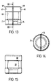
- This collet comprises two collet portions 66 and 67 which are made from a resilient plastics material, for example polypropylene.
- Each of the portions 66, 67 is substantially semi circular and has a closed end provided by an upper wall 68 and a semi circular cavity 69. The cavity is shaped to correspond to the neck 70 and head 71 of the modular prosthesis 72.
- the collet portion 67 has a flat 73 on one side and as will be seen by the drawings each of the collet portions do not extend around a full half circumference of the spigot but leave a gap 74 between them.
- the collet and socket 65 are dimensioned so that the collet and spigot are a push fit into the socket which is sufficient to firmly secure and hold the spigot in place, but allowing the spigot and collet to be easily withdrawn.
- the socket 65 is also provided with a flat 75 on the portion of its wall intended to be adjacent the engagement wall 140 on the locking plate 131 in the construction shown in Figure 10.
- the outer end of the rod 57 carries a shaped end 76 which is adapted to engage in a feature on the shoulder of the prosthesis 72 in a similar manner to the construction shown in Figure 1 but in this construction it will be seen from Figure 6 that the insertion axis 78 is axially aligned with the axis 79 of the prosthesis.
- a split collet of the kind shown in Figures 13, 14 and 15 is first located on the spigot 71 of the prosthesis and is then pushed into the socket 65.
- the shaped end of the rod 57 is extended against the spring 58 by operating the handle 71 so that the end 76 enters the opening in the prosthesis.
- the prosthesis is now firmly attached to the inserter but is prevented from rotating against axial and angular movement in relation to the insertion axis 78.
- any downward insertion load by the surgeon whilst the prosthesis is implanted is partly carried by the rod 57 by the surgeon inserting a pressure on the trigger 61.
- Part of the load can also be carried by the attachment means 63.
- the inserter can he removed by one hand merely by relieving the pressure on the trigger 61 which allows the location means 76 and 77 to be released and the attachment means can also be released by pulling the socket 65 away from the split collet.
- Figure 10 shows another construction according to the invention which is somewhat similar to that shown in Figure 6 but in which retractable means are included for retaining the collet in place and release means are included for simultaneously actuating the retractable collet retaining means and the retractable location means.
- the device comprises an open framed body 100 in which a sliding rod 101 is mounted.
- the axis of the rod 101 which also forms the insertion axis is indicated by reference numeral 102.
- the rod carries a rigidly attached collar 103 on one side of which is located a compression spring 104 the other end of which bears against the frame of the main body 100 so that the rod is biased towards the right, as shown in the drawing.
- a loosely mounted short spring 105 Located on the other side of the collar 103 is a loosely mounted short spring 105 the operation of which will be described hereafter.
- a third compression spring 106 is also carried on the rod one end of which bears against a frame member 107 and the other end of which acts against an actuator 108 which is also carried on the rod and is in the form of a plate the upper end of which is provided with a slot 109 which can slide along a guide 110 in the upper part of the body frame.
- the lower part of the actuator 108 is cut away to provide a further guide surface 111 which can slide along a lower frame portion 112.
- a first operating trigger 113 is also carried on the lower frame 112 by a pivot 114.
- the lower part of the first trigger 113 is formed as an operating lever 115 and the upper part 116 is shaped to engage the lower part of the actuator 108.
- An extension of the lower part of the frame 112 is shaped to form a handle 117 on which is pivoted a second operating lever 118 the upper part of which is in the form of a hook 119 which engages the lower part of a locking member 120.
- the locking member is freely mounted on the rod 101 and the upper part is provided with a yoke 121 which engages on both sides of a retaining ridge 122 on the main body 100.
- a fourth compression spring 123 is carried on the rod 101 between a rear frame member 124 through which the rod 101 passes and the locking member 120.
- the rod 101 passes from the body 100 through a tubular extension 125 and emerges as a locating pin 126 which provides locating means.
- a bracket 127 is carried on the end of the extension 125, and has a socket 128 which forms part of the attachment means.
- the construction of the attachment means is most clearly shown in Figures 11 and 12.
- the side of the socket 128 is cut away to provide a slot 129 which extends through the bracket 127 and into the cylindrical extension 125 as indicated by reference numeral 130.
- Collet retaining means are provided in the form of a collet lock provided by a flat locking plate 131 which is located in the slot 129 and pivoted by a pin 132.
- the locking plate is bifurcated at 133 to provide a pair of arms which pass each side of a reduced portion 134 of the rod 101.
- the reduced portion 134 terminates at one end in an abutment ridge 135 and at the other in an enlargement 136 as is most clearly shown in Figure 11.
- the locking plate 131 also carries a locking hook 137 having an engagement face 138 and an engagement wall 140.
- the socket 128 is dimensioned to receive a split collet of the type shown in Figures 13, 14 and 15.
- the opening in the locking member 120 is slightly larger than the diameter of the operating rod 101 but because the spring 123 pushes the lever outwardly away from the frame member 124 the lever tends to rotate about the retaining ridge 122 so that the opening operates to jam against the rod 101 and prevent movement.
- the second operating lever 118 When the second operating lever 118 is operated it rotates and the hook 119 presses against the lower end of the locking lever so that it rotates against the action of the spring 123 and thus frees the rod 101.
- the actuator plate 108 is a loose fit on the rod 101 so that although it can tilt under the action of the trigger 113 it then locks onto the rod 101 and acts to move it against the action of the third spring 106.
- the trigger can move the actuating plate to provide an "inching" movement or as a single or separate movements to advance the rod to the operating position.
- the third spring 106 pushes the actuating plate 101 to the position shown in Figure 10 so that the plate always returns to this position after use of the trigger irrespective of the position of the rod 101.
- the two piece collet 68 is first placed in position on the neck and tapered spigot of the prosthesis. With the rod 101 in the retracted position the collet and prosthesis are inserted into the socket 128 and the first trigger is operated to move the rod 101 into its operative position with the locating pin entering a suitable opening in the prosthesis and the hook 137 engaging over the end of the collet, at the same time the collet is slightly compressed to hold it firmly in the socket by the wall 140.
- the prosthesis can now be inserted by the surgeon holding the handle 117 and once the insertion has been completed the inserter can simply be removed by one hand by operating the lever 118 which releases both the locating means and the attachment means provided by the locking hook 137 and wall 140 acting on the collet. With these released the inserter can be easily removed, the whole operation being carried out by one hand.
- Figure 16 shows another construction according to the invention which is somewhat similar to that shown in Figures 10 to 15 but in which the location means does not retract.
- the same reference numerals are used to indicate similar parts to those shown in Figures 10 to 12 and a split collet similar to that shown in Figures 13 to 15 is employed.
- rod 101 is provided with a groove 150 and the outer end 151 of the rod is carried in a blind bore 152 provided in a housing 153.
- This housing is screw threaded at 154 into the outer end of the tubular extension 125.
- the housing is shaped to provide a locating pin 155 which is appropriately shaped to engage a suitable opening in the prosthesis.
- a locating pin 155 which is appropriately shaped to engage a suitable opening in the prosthesis.
- the bifurcated part 133 of the locking plate which provides the pair of arms engage in the groove 150 and are acted upon by the abutment ridge 135 provided by one side of the groove.
- a second abutment ridge 156 provided by the other side of the groove.
- the triggers 113 and 117 are operated in a similar manner to that described with regard to Figures 10 to 12 but it will be seen that when the rod 101 is advanced it only operates on the locking plate 131, the outer end 151 of the rod 101 sliding in the blind bore 152. Retracting of the locking plate 131 is again achieved in a similar manner to operation of the construction shown in Figures 10 to 12 but in this case the second abutment ridge 156 acts against the bifurcation 133 to move the locking plate 131 to its retracted position.
- This construction is used in a similar manner to that described with regard to Figures 10 to 12 but in this case the location means provided by the location pin 155 is pushed into position and the trigger 113 is operated to lock the spigot into the attachment means. In order to remove the inserter the trigger 118 is operated to release the locking plate 131 so that the inserter can be removed.
- locating means can be employed, for example as shown in Figures 7, 8 and 9, there are others which could be equally effective.
- a locating means can be used which only engages one side wall of the prosthesis to be inserted, the device employing a flat surface which has sufficient length to effectively prevent angular rotation of the prosthesis about its spigot in both directions.
- a prosthesis inserter comprises a prosthesis holder which includes a tubular main body component 20 having a longitudinal axis coaxial with the insertion axis the distal end of which is attached by a fixing screw 215 which bears on a section of reduced diameter 216 to an operating handle 202.
- the handle 202 houses a pivotal lever 203 which rotates around pivot 214, and one end of which bears upon one end of an operating rod 204 which can travel along the insertion axis.
- the operating rod 204 is mounted coaxially with the main body component 201 in a bore and a spring 205 is provided between the distal end of the operating arm and the distal end of the main body component 201 to bias the rod 204 towards a rest position.
- the proximal end of the operating rod arm 204 has a shaped end 206 of reduced diameter for limited insertion into the femoral prosthesis 207.
- the proximal end of the main body component 201 has tapered flats 208 to produce a tapering effect when inserted into a tapered socket 210 of an attachment element 209 the flats precluding torsional movement of the main body component 201 in the element 209.
- the tapered socket 210 allows limited entry of the main body component 201 while allowing full passage of the operating rod 204.
- the attachment element 209 also has an additional tapered socket 211 which fits over the tapered spigot 212 of the femoral prosthesis 207 to cooperate therewith and to firmly locate thereon.
- An engagement feature 213 is provided on the shoulder of the prosthesis 207 for locating the shaped end of the operating rod 204 so that when engaged if ensures that the entire assembly is held rigid.
- the parts are assembled by firstly firmly inserting the tapered spigot 212 of the femoral prosthesis 207 into the tapered socket 211 of the attachment element 209, then by firmly inserting the tapered end 208 of the tubular main body component into the tapered socket 210 of the attachment element 209 and the shaped end 206 of the operating rod 204 into the engagement feature 213 of the prosthesis 207.
- the pivotal lever 203 is rotated about the pivot 214 which causes one end of the lever to bear upon the distal end of the operating rod.
- This causes the spring 205 to be compressed allowing the operating rod 204 to travel within the tubular main body component 201.
- the shaped end 206 of the operating rod 204 is now caused to bear upon the femoral prosthesis 207 to release the tubular main body component 201 from the attachment element 209 and allowing the attachment element 209 to be released from the tapered spigot 212 of the femoral prosthesis 207.
- FIGS 23 and 24 show an alternative construction of attachment element indicated by reference numeral 230.
- the same reference numerals are used to indicate similar parts to those shown in Figures 18 to 22 but in this arrangement the tapered sockets 210 and 211 are interconnected by a bridge 231 which has a slight amount of flexibility.
- the slight amount of flexibility allows the front face 232 of the portion providing the socket 210 to bear against the shoulder of the prosthesis and when the rod 204 is released to move away thus facilitating release.
- FIG. 23 and 24 The construction shown in Figures 23 and 24 is also provided with a pair of spaced apart wings 233 to allow the connection of means to control the position and depth of the prosthesis when it is placed in position with respect to the bone into which it is to be inserted in the manner described in the Applicant's copending British Patent Application GB-A-9804471.2 (H.67).
- Figure 25 shows another construction of attachment element, indicated by reference numeral 240, which is similar to that shown in Figures 23 and 24 but in which the wings 233 are not included and the closed end of the socket 210 is deleted.
- the socket is replaced by a tapered bore 241 so that the end of the main body component 201 can pass through it and directly engage the shoulder of the prosthesis 212.
- advantages with this construction in as much that axial forces applied by the handle through the main body component 201 can be directly transferred to the shoulder of the prosthesis.
- the apparatus works in the same way as that described with regard to the other constructions.
Landscapes
- Health & Medical Sciences (AREA)
- Transplantation (AREA)
- Orthopedic Medicine & Surgery (AREA)
- Heart & Thoracic Surgery (AREA)
- Cardiology (AREA)
- Oral & Maxillofacial Surgery (AREA)
- Engineering & Computer Science (AREA)
- Biomedical Technology (AREA)
- Physical Education & Sports Medicine (AREA)
- Vascular Medicine (AREA)
- Life Sciences & Earth Sciences (AREA)
- Animal Behavior & Ethology (AREA)
- General Health & Medical Sciences (AREA)
- Public Health (AREA)
- Veterinary Medicine (AREA)
- Prostheses (AREA)
Abstract
Description
- This invention relates to a prosthesis inserter which is particularly, although not exclusively, applicable for use for inserting a femoral stem prosthesis.
- It is particularly difficult to grip the femoral component of a total hip prosthesis without damaging the stem. Damage to a femoral component in the region of the neck may lead to a reduction in the fatigue life of the component since the damage may lead to the initiation of cracks. Furthermore, damage to the spigot of a modular design, that is a stem component in which heads of different sizes or shapes can be fitted to a spigot, may lead to problems with the engagement of the prosthetic femoral head on the stem. Consequently there are many designs of stem introducing instruments which employ protection of the spigot and the neck of the stem.
- It has also been found with earlier designs which clamp only the spigot to the stem that, although the inserter may be tightly clamped to the spigot, there can be rotary movement. The rotary movement can he a nuisance during insertion and can result in an incorrect and misaligned insertion. Improving the force used to clamp the spigot to prevent the rotary movement is likely to cause damage to the spigot.
- In many cases it has been found necessary to include a feature on the stem, such as a dimple or a depression into which the stem introducing instrument engages to provide a secure attachment of the stem to the introducer. With such a design of stem introducing instrument, it is usual to achieve engagement onto the stem by advancing an attachment element which engages with the stem. In previous designs the method of advancement has required the surgeon to use two hands to advance the attachment element to secure the stem and, more importantly, has required two hands to be used to effect release. The use of two hands is indicative of the complexity of the methods of engagement and, for a cemented stem, the action to disengage the stem introducing instrument may lead to a disruption of the partially cured cement mantle which may impair the long term result of the implantation. It is therefore desirable to achieve a design of prosthesis implantation inserter instrument which enables the stem to be released with one hand with the minimum disturbance to the cement mantle.
- The present invention is intended to overcome both the problems referred to above.
- According to the present invention a prosthesis implantation inserter comprises attachment means for securing and holding the prosthesis to be implanted, location means spaced away from the attachment means and adapted to engage the prosthesis to prevent axial and angular movement thereof in relation to the insertion axis of the inserter and release means adapted for single handed operation for releasing the attachment means or the location means or both.
- The construction may be arranged so that the implantation loads applied to the inserter are transmitted to the prosthesis to be implanted through the attachment means, alternatively the construction can be such that implantation loads applied to the inserter are transmitted to the prosthesis to be implanted through the location means.
- The attachment means is preferably adapted to attach to the head spigot of a femoral component to be inserted and may comprise a resilient adapter shaped to surround the spigot of the prosthesis and the provision of engagement means which grasp the resilient adapter.
- Thus, the resilient adapter may include an engagement claw or claws which locate in the engagement means.
- In another construction the resilient adapter can be in the form of a collet having a flange which is adapted to engage beneath the head spigot of the prosthesis to be implanted and releasable means for retaining the collet in place. If desired the collet can be split.
- With this construction operating means can be included for simultaneously actuating the releasable collet retaining means and the releasable location means.
- In another construction the attachment means can include an attachment element adapted to attach to the head spigot of said femoral component, and to also receive said location means.
- This attachment element can have means for firm attachment to the inserter.
- Thus the attachment element can have a tapered socket dimensioned to cooperate with the spigot of said prosthesis and a tapered socket to co-operate with a suitable portion of said inserter adjacent said location means.
- In a preferred construction the attachment element is adapted to engage the proximal shoulder of the femoral component to be implanted.
- The releasable location means can be adapted to engage a location feature on the prosthesis to be implanted and such a feature can be provided by a side or sides of the prosthesis. With this arrangement the location means can be in the form of a retractable bifurcated portion which engages the sides of the prosthesis.
- Alternatively or additionally the location means may include a retractable pin adapted to engage a location opening in the prosthesis.
- The device may include a body portion which extends along the axis of insertion, a handle and a trigger for operating the releasable location means.
- The releasable location means acts to lock the prosthesis in position to prevent rotation and the device can thus easily be removed from the prosthesis once it has been inserted by simple operation of the operating trigger which acts to remove all the connections.
- In the earlier construction referred to above in which the resilient adapter includes a claw or claws the operation is again single handed because the location means can be withdrawn and the attachment means simply disconnected.
- If desired means can be included to hold the retractable location means in a withdrawn position thus assisting removal.
- The invention can be performed in various ways and some embodiments will now be described by way of example and with reference to the accompanying drawings in which :
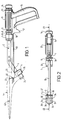
- Figure 1 is a side elevation of a first construction of prosthesis inserter according to the invention with a prosthesis to be inserted location in position;
- Figure 2 is a plan view from below of the inserter shown in Figure 1;
- Figure 3 is a cross-sectional side elevation of the inserter shown in Figures 1 and 2 on the lines III-III of Figure 2;
- Figure 4 is an isometric view of an adapter for use with the inserter;
- Figure 5 is an end elevation of the adapter shown in Figure 4;
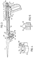
- Figure 6 is a side elevation of an alternative construction according to the invention;
- Figures 7, 8 and 9 show alternative forms of location means;
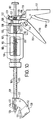
- Figure 10 is a side elevation of another construction according to the invention;
- Figure 11 is an enlarged cross-sectional side elevation of part of the construction shown in Figure 10;
- Figure 12 is a plan view from below of the construction shown in Figure 11;
- Figure 13 is a side elevation of a two part split collet for use in the construction shown in Figures 6, 10, 11 and 12;
- Figure 14 is a plan view from above of the collet shown in Figure 13;
- Figure 15 is an end elevation on the lines XV-XV of Figure 13 showing one of the collet parts;
- Figure 16 is a cross-sectional side elevation of part of another construction according to the invention;
- Figure 17 is a diagrammatic perspective view of the tray which forms the attachment means in the construction shown in Figures 1 to 5;
- Figure 18 is a diagrammatic part cross sectional side elevation of a first construction of prosthesis inserter according to the invention;
- Figure 19 is an isometric view of the attachment element shown in Figure 18;
- Figure 20 is another isometric view of the attachment element shown in Figure 18;
- Figure 21 is an isometric view of the prosthesis holder with the attachment element removed;
- Figure 22 is an exploded diagrammatic cross sectional side view of the prosthesis inserter according to the invention;
- Figure 23 is an isometric view of an alternative form of attachment element which can be used with the construction shown in Figures 18 to 22;
- Figure 24 is a cross-sectional side elevation of the attachment insert shown in Figure 23; and
- Figure 25 is a cross-sectional view of another alternative construction of attachment element.
-
- As shown in Figures 1 to 5 a prosthesis inserter comprises a main body component 1 having a longitudinal axis and which is the insertion axis, indicated by chain line 2. The main body component 1 carries a cranked
extension 3 on which is mounted attachment means 4 for holding a femoral prosthesis component indicated bychain lines 5. The main body component 1 has a cylindrical support 6 on which is carried a compression spring 7 which bears against a slidingcollar 8 also mounted on the cylindrical support 6. Thecollar 8 is provided with a circumferential groove 9 and is connected to anoperating rod 10. - The spring 7 is housed within a
casing 11 having a cylindrical bore 12 to enable it to be carried on the cylindrical support 6 and the end of this support has a square section portion 33 and a screw threadedextension 33a on which is located a rotatable locatingdisc 13 and a screw threadedlock knob 14. The end of the bore 12 is of square cross-section to locate on the square section 33 of the support 6. - The lower part of the
casing 11 is extended to form ahandle 15 and aguide slot 16 is provided between the handle and the main part of the casing to house atrigger 17. The trigger has anupstanding abutment 18 which locates in the annular groove 9 and is also provided with anextension 19 which is shaped to fit into anopening 20 provided on the outer circumference of thedisc 13. - The end of the
rod 10 spaced away from thehandle 15 is guided in an extendedbore 31 located in a projectingboss 21 on theextension 3 and theouter end 22 of therod 10 is shaped, in this example in the form of a truncated cone, to fit closely into a location feature in the form of a location opening 23 in theprosthesis 5. - The prosthesis is of modular design, that is a stem component on which heads of different sizes or shapes can he fitted to a
spigot 24. - In order to prevent damage to the spigot an
adapter 25 is provided which is shown in Figures 4 and 5. This adapter can be made from any suitable material, for example metal or a plastics material such as a resilient polycarbonate, and is in the form of acollar 26 one side of which is split to provide anopening 27. A pair ofclaws 28 extend one on each side of theopening 27 and theirouter faces 29 are chamfered, as is most clearly shown in Figure 5. - The internal bore 30 of the collar is slightly less than the outer circumference of the
tapered spigot 24 so that it is a push fit onto it, the natural resilience of the material allowing the collar to be placed in position. - The attachment means 4 is in the form of a substantially square tray, as is most clearly shown in Figure 17. The tray has three
upstanding side walls 34 the upper portions of which are chamfered at 35. The remaining side is open apart from abar 36 which extends between the twoparallel side walls 34 and leaves beneath it anopening 37 to theflat floor 38 of the tray. - The angle of the base of the tray is appropriate for the angle of the neck to the stem of the prosthesis to be inserted.
- To attach a femoral component to be inserted a
collar 25 is first placed over thespigot 24. Theclaws 28 are then pushed into the tray and rotated about thebar 36 so that they extend into theopening 37. The dimensions of the claws and the distance from their front faces to the outer circumference of the collar is arranged so that the collar together with the femoral component is locked between thebar 36 and theopposed end wall 34 within the portion of the wall beneath thechamfer 35. Moreover, the width between theparallel walls 34 and the distance between the chamfered faces 29 and the remainder of the walls of the claws relative to the twoparallel walls 35 is arranged so that there is a constricting effect tending to close the gap in the collar so that the spigot of the femoral component is tightly clamped. - With the femoral component located on this attachment means it will be seen that the centre line of the femoral component, indicated by
reference numeral 40, and the centre line 2 of the inserter are substantially in axial alignment. In the construction being described the alignment is slightly displaced but the displacement or the alignment could be as desired. - If this were the only means of holding the prosthesis onto the inserter then there is the possibility of the spigot rotating in the collet, despite the clamping effect. The prosthesis is however provided with a location feature in the form of the location opening 23 in the shoulder of the prosthesis. As the prosthesis is rotated into the attachment means the
trigger 18 is retracted thus compressing the spring 7 and moving therod 10 rearwardly. Once the locking pin is approximately in position the trigger can be released and slight further movement will allow the engagement locking pin to move into place. Thus the prosthesis is now held by the attachment means 4 and the retractable location means provided by thepin 10 engage the prosthesis at a point spaced away from the attachment means and prevent axial and angular movement in relation to the insertion axis 2 of the inserter. - Because the
pin 10 is biased into the location opening 23 any downward insertion load by the surgeon whilst the prosthesis is implanted will not be carried by thepin 10 but by theend 32 of theboss 21 bearing against the shoulder of the prosthesis and is also partly carried by the crankedstem 3 which transfers the load to the prosthesis through the attachment means 4. Thepin 10 merely acts to prevent axial and angular movement. - Once the surgeon has completed the insertion and provided the loading on the cement the inserter can be removed by one hand, merely be operating the
trigger 17 to remove therod 10 from the location opening 23 to release the location means and by then simply rotating the inserter about thepin 36 so that the attachment means are also released without unnecessarily disturbing the implanted prosthesis and without having to use both hands. - Figures 7, 8 and 9 show various alternative constructions to provide the location means and which can be employed in any of the constructions described herein. Thus, Figure 7 shows a construction in which the end of the
rod 10 has asingle taper 42 and arounded end 43 which mate with an appropriately shaped opening in theprosthesis 5. - Figure 8 shows a construction in which the end of the rod has a semi
circular shape 44 with an appropriate opening in theprosthesis 5 and Figure 9 shows the end of therod 10 carrying abifurcated head 45 which is shaped and dimensioned to fit over theshoulder 46 of theprosthesis 5. In this case the location feature is formed by thesides - The angular position of the
handle 15 in relation to the crankedextension 3 can be altered by relocating it on the square section portion 33 of the support 6. In order to rotate the handle to a different angular position thelock knob 14 is released by unscrewing it sufficiently to move thecasing 11 to the right with respect to the support 6 to disengage the square section. The handle is then moved to the desired angular position and slid back onto the square section being subsequently clamped in position by thelock knob 14. - Figure 6 shows another construction but employing a different form of attachment means. In this arrangement a
main body 55 carries ahollow extension 56 in which is mounted aretractable rod 57. The rod is biased towards a retracted position by acompression spring 58 which acts between thebody 55 and anend knob 59. Thebody 55 carries ahandle 60 and anoperating trigger 61 which is pivoted to the handle by apin 62. The end of thetrigger 61 carries a bifurcated arm which surrounds a portion of reduced diameter of the rod (not shown) so that operation of the trigger acts to move the rod in a direction away from the handle and to cause thespring 58 to be compressed. - The end of the
extension 56 spaced away from thehandle 60 carries attachment means 63 which are provided by abracket 64 which is rigidly attached to theextension 56. The other end of the bracket is provided with asocket 65 which is shaped to receive a spigot adapter in the form of a two piece split collet of the kind shown in Figures 13, 14 and 15. This collet comprises twocollet portions portions upper wall 68 and a semicircular cavity 69. The cavity is shaped to correspond to theneck 70 andhead 71 of themodular prosthesis 72. Thecollet portion 67 has a flat 73 on one side and as will be seen by the drawings each of the collet portions do not extend around a full half circumference of the spigot but leave agap 74 between them. The collet andsocket 65 are dimensioned so that the collet and spigot are a push fit into the socket which is sufficient to firmly secure and hold the spigot in place, but allowing the spigot and collet to be easily withdrawn. - The
socket 65 is also provided with a flat 75 on the portion of its wall intended to be adjacent theengagement wall 140 on thelocking plate 131 in the construction shown in Figure 10. - The outer end of the
rod 57 carries a shaped end 76 which is adapted to engage in a feature on the shoulder of theprosthesis 72 in a similar manner to the construction shown in Figure 1 but in this construction it will be seen from Figure 6 that theinsertion axis 78 is axially aligned with theaxis 79 of the prosthesis. - In order to attach the inserter to the prosthesis a split collet of the kind shown in Figures 13, 14 and 15 is first located on the
spigot 71 of the prosthesis and is then pushed into thesocket 65. The shaped end of therod 57 is extended against thespring 58 by operating thehandle 71 so that the end 76 enters the opening in the prosthesis. The prosthesis is now firmly attached to the inserter but is prevented from rotating against axial and angular movement in relation to theinsertion axis 78. - With this construction any downward insertion load by the surgeon whilst the prosthesis is implanted is partly carried by the
rod 57 by the surgeon inserting a pressure on thetrigger 61. Part of the load can also be carried by the attachment means 63. - When the insertion has been completed the inserter can he removed by one hand merely by relieving the pressure on the
trigger 61 which allows the location means 76 and 77 to be released and the attachment means can also be released by pulling thesocket 65 away from the split collet. - In the construction shown in Figure 6 location means of the kind shown in Figures 7, 8 and 9 can also be used.
- Figure 10 shows another construction according to the invention which is somewhat similar to that shown in Figure 6 but in which retractable means are included for retaining the collet in place and release means are included for simultaneously actuating the retractable collet retaining means and the retractable location means.
- As shown in Figure 10 the device comprises an open framed body 100 in which a sliding
rod 101 is mounted. The axis of therod 101 which also forms the insertion axis is indicated byreference numeral 102. The rod carries a rigidly attached collar 103 on one side of which is located acompression spring 104 the other end of which bears against the frame of the main body 100 so that the rod is biased towards the right, as shown in the drawing. Located on the other side of the collar 103 is a loosely mountedshort spring 105 the operation of which will be described hereafter. - A third compression spring 106 is also carried on the rod one end of which bears against a frame member 107 and the other end of which acts against an actuator 108 which is also carried on the rod and is in the form of a plate the upper end of which is provided with a slot 109 which can slide along a guide 110 in the upper part of the body frame. The lower part of the actuator 108 is cut away to provide a
further guide surface 111 which can slide along alower frame portion 112. Afirst operating trigger 113 is also carried on thelower frame 112 by apivot 114. The lower part of thefirst trigger 113 is formed as an operatinglever 115 and theupper part 116 is shaped to engage the lower part of the actuator 108. - An extension of the lower part of the
frame 112 is shaped to form ahandle 117 on which is pivoted asecond operating lever 118 the upper part of which is in the form of ahook 119 which engages the lower part of a lockingmember 120. The locking member is freely mounted on therod 101 and the upper part is provided with ayoke 121 which engages on both sides of a retaining ridge 122 on the main body 100. - A
fourth compression spring 123 is carried on therod 101 between a rear frame member 124 through which therod 101 passes and the lockingmember 120. - The
rod 101 passes from the body 100 through atubular extension 125 and emerges as a locatingpin 126 which provides locating means. - A
bracket 127 is carried on the end of theextension 125, and has asocket 128 which forms part of the attachment means. - The construction of the attachment means is most clearly shown in Figures 11 and 12. The side of the
socket 128 is cut away to provide aslot 129 which extends through thebracket 127 and into thecylindrical extension 125 as indicated byreference numeral 130. - Collet retaining means are provided in the form of a collet lock provided by a
flat locking plate 131 which is located in theslot 129 and pivoted by apin 132. The locking plate is bifurcated at 133 to provide a pair of arms which pass each side of a reducedportion 134 of therod 101. The reducedportion 134 terminates at one end in anabutment ridge 135 and at the other in anenlargement 136 as is most clearly shown in Figure 11. The lockingplate 131 also carries alocking hook 137 having anengagement face 138 and anengagement wall 140. - The
socket 128 is dimensioned to receive a split collet of the type shown in Figures 13, 14 and 15. - In Figures 10, 11 and 12 the inserter is shown in the position in which both the locating
pin 126 and lockingplate 131 are in the positions they take up when a prosthesis is attached to the inserter. In this position therod 101 is in its left hand position in the body portion 100 and thefirst compression spring 104 is compressed. It will also be seen that thebifurcated portion 133 of the locking plate is against theabutment ridge 134 of therod 101 which has caused theengagement face 138 of thelocking hock 137 to extend over the end of thesocket 128. In this position theinner face 140 extends slightly into the general curvature of thesocket 128 thus acting to compress the collet when it is in position. In Figure 11 the amount of encroachment of theface 140 has been exaggerated to show how it operates. - From Figure 10 it will be seen that in this position the
second spring 105 is still free on therod 101 and that the third spring 106 is uncompressed and is holding the plate 108 against thetrigger 113. Thefourth spring 123 is still acting against the lockingmember 120. - The opening in the locking
member 120 is slightly larger than the diameter of the operatingrod 101 but because thespring 123 pushes the lever outwardly away from the frame member 124 the lever tends to rotate about the retaining ridge 122 so that the opening operates to jam against therod 101 and prevent movement. When thesecond operating lever 118 is operated it rotates and thehook 119 presses against the lower end of the locking lever so that it rotates against the action of thespring 123 and thus frees therod 101. With the rod freed from the locking member thecompression spring 104 which, in the position shown in Figure 10 is compressed, can now operate and move against the collar 103 thus pushing the operating rod 1 to the right and into a retracted position which is determined by theenlargement 136 on therod 101 engages thebifurcated end 133 of the locking plate which not only causes the locking plate to rotate about thepivot 132 to a retracted position where thehook 137 is clear of thesocket 128 hut acts to restrain the retracting movement of therod 101. - The actuator plate 108 is a loose fit on the
rod 101 so that although it can tilt under the action of thetrigger 113 it then locks onto therod 101 and acts to move it against the action of the third spring 106. Thus, the trigger can move the actuating plate to provide an "inching" movement or as a single or separate movements to advance the rod to the operating position. After each movement of the trigger, and when the trigger is relaxed, the third spring 106 pushes theactuating plate 101 to the position shown in Figure 10 so that the plate always returns to this position after use of the trigger irrespective of the position of therod 101. - In order to use the inserter shown in Figures 10, 11 and 12 the two
piece collet 68 is first placed in position on the neck and tapered spigot of the prosthesis. With therod 101 in the retracted position the collet and prosthesis are inserted into thesocket 128 and the first trigger is operated to move therod 101 into its operative position with the locating pin entering a suitable opening in the prosthesis and thehook 137 engaging over the end of the collet, at the same time the collet is slightly compressed to hold it firmly in the socket by thewall 140. The prosthesis can now be inserted by the surgeon holding thehandle 117 and once the insertion has been completed the inserter can simply be removed by one hand by operating thelever 118 which releases both the locating means and the attachment means provided by the lockinghook 137 andwall 140 acting on the collet. With these released the inserter can be easily removed, the whole operation being carried out by one hand. - Figure 16 shows another construction according to the invention which is somewhat similar to that shown in Figures 10 to 15 but in which the location means does not retract. The same reference numerals are used to indicate similar parts to those shown in Figures 10 to 12 and a split collet similar to that shown in Figures 13 to 15 is employed.
- In this
construction rod 101 is provided with a groove 150 and theouter end 151 of the rod is carried in ablind bore 152 provided in ahousing 153. This housing is screw threaded at 154 into the outer end of thetubular extension 125. - The housing is shaped to provide a
locating pin 155 which is appropriately shaped to engage a suitable opening in the prosthesis. Although it will be appreciated that the shape of this locating means could be in any of the forms shown in Figures 7, 8 and 9. - With this construction the
bifurcated part 133 of the locking plate which provides the pair of arms engage in the groove 150 and are acted upon by theabutment ridge 135 provided by one side of the groove. Asecond abutment ridge 156 provided by the other side of the groove. - The
triggers rod 101 is advanced it only operates on thelocking plate 131, theouter end 151 of therod 101 sliding in theblind bore 152. Retracting of thelocking plate 131 is again achieved in a similar manner to operation of the construction shown in Figures 10 to 12 but in this case thesecond abutment ridge 156 acts against thebifurcation 133 to move thelocking plate 131 to its retracted position. - This construction is used in a similar manner to that described with regard to Figures 10 to 12 but in this case the location means provided by the
location pin 155 is pushed into position and thetrigger 113 is operated to lock the spigot into the attachment means. In order to remove the inserter thetrigger 118 is operated to release thelocking plate 131 so that the inserter can be removed. - Once again it will be appreciated that all the actions can be carried out with one hand and this construction demonstrates a device in which the release means act only on the location means.
- It will be appreciated that although various forms of locating means can be employed, for example as shown in Figures 7, 8 and 9, there are others which could be equally effective. For example, a locating means can be used which only engages one side wall of the prosthesis to be inserted, the device employing a flat surface which has sufficient length to effectively prevent angular rotation of the prosthesis about its spigot in both directions.
- In the construction shown in Figures 18 to 22 a prosthesis inserter according to the present invention comprises a prosthesis holder which includes a tubular
main body component 20 having a longitudinal axis coaxial with the insertion axis the distal end of which is attached by a fixingscrew 215 which bears on a section of reduceddiameter 216 to anoperating handle 202. The handle 202 houses apivotal lever 203 which rotates aroundpivot 214, and one end of which bears upon one end of anoperating rod 204 which can travel along the insertion axis. The operatingrod 204 is mounted coaxially with themain body component 201 in a bore and aspring 205 is provided between the distal end of the operating arm and the distal end of themain body component 201 to bias therod 204 towards a rest position. The proximal end of the operatingrod arm 204 has ashaped end 206 of reduced diameter for limited insertion into thefemoral prosthesis 207. The proximal end of themain body component 201 has taperedflats 208 to produce a tapering effect when inserted into atapered socket 210 of anattachment element 209 the flats precluding torsional movement of themain body component 201 in theelement 209. - The tapered
socket 210 allows limited entry of themain body component 201 while allowing full passage of the operatingrod 204. Theattachment element 209 also has an additionaltapered socket 211 which fits over thetapered spigot 212 of thefemoral prosthesis 207 to cooperate therewith and to firmly locate thereon. - An
engagement feature 213 is provided on the shoulder of theprosthesis 207 for locating the shaped end of the operatingrod 204 so that when engaged if ensures that the entire assembly is held rigid. - The parts are assembled by firstly firmly inserting the
tapered spigot 212 of thefemoral prosthesis 207 into the taperedsocket 211 of theattachment element 209, then by firmly inserting thetapered end 208 of the tubular main body component into the taperedsocket 210 of theattachment element 209 and theshaped end 206 of the operatingrod 204 into theengagement feature 213 of theprosthesis 207. - To release the
femoral prosthesis 207 thepivotal lever 203 is rotated about thepivot 214 which causes one end of the lever to bear upon the distal end of the operating rod. This causes thespring 205 to be compressed allowing the operatingrod 204 to travel within the tubularmain body component 201. Theshaped end 206 of the operatingrod 204 is now caused to bear upon thefemoral prosthesis 207 to release the tubularmain body component 201 from theattachment element 209 and allowing theattachment element 209 to be released from thetapered spigot 212 of thefemoral prosthesis 207. - Figures 23 and 24 show an alternative construction of attachment element indicated by
reference numeral 230. In this construction the same reference numerals are used to indicate similar parts to those shown in Figures 18 to 22 but in this arrangement the taperedsockets bridge 231 which has a slight amount of flexibility. Thus, when the parts are assembled and are in place on theprosthesis 207, the slight amount of flexibility allows thefront face 232 of the portion providing thesocket 210 to bear against the shoulder of the prosthesis and when therod 204 is released to move away thus facilitating release. - The construction shown in Figures 23 and 24 is also provided with a pair of spaced apart
wings 233 to allow the connection of means to control the position and depth of the prosthesis when it is placed in position with respect to the bone into which it is to be inserted in the manner described in the Applicant's copending British Patent Application GB-A-9804471.2 (H.67). - Figure 25 shows another construction of attachment element, indicated by
reference numeral 240, which is similar to that shown in Figures 23 and 24 but in which thewings 233 are not included and the closed end of thesocket 210 is deleted. Thus, the socket is replaced by atapered bore 241 so that the end of themain body component 201 can pass through it and directly engage the shoulder of theprosthesis 212. In certain requirements there are advantages with this construction in as much that axial forces applied by the handle through themain body component 201 can be directly transferred to the shoulder of the prosthesis. For fitting and removal the apparatus works in the same way as that described with regard to the other constructions.
Claims (22)
- A prosthesis implantation inserter comprising attachment means for securing and holding the prosthesis to be implanted, location means spaced away from the attachment means and adapted to engage the prosthesis to prevent axial and angular movement thereof in relation to the insertion axis of the inserter and release means adapted for single handed operation for releasing the attachment means or the location means or both.
- A prosthesis implantation inserter as claimed in claim 1 in which implantation loads applied to the inserter are transmitted to the prosthesis to be implanted through the attachment means.
- A prosthesis implantation inserter as claimed in claim 1 in which implantation loads applied to the inserter are transmitted to the prosthesis to be implanted through the location means.
- A prosthesis implantation inserter as claimed in claims 1 to 3 in which said attachment means is adapted to attach to the head spigot of a femoral component to be implanted.
- A prosthesis implantation inserter as claimed in claim 4 in which said attachment means includes a resilient adapter shaped to surround the head spigot of said prosthesis to be implanted and the provision of engagement means which grasp said resilient adapter.
- A prosthesis implantation inserter as claimed in claim 5 in which said resilient adapter includes an engagement claw or claws which locate in said engagement means.
- A prosthesis implantation inserter as claimed in claim 5 in which said resilient adapter is in the form of a collet having a flange which is adapted to engage beneath the head spigot of said prosthesis to be implanted and releasable means for retaining said collet in place.
- A prosthesis implantation inserter as claimed in claim 7 in which said collet is split.
- A prosthesis implantation inserter as claimed in claim 7 or claim 8 including operating means for simultaneously actuating said releasable collet retaining means and said location means.
- A prosthesis implantation inserter as claimed in claim 4 in which said attachment means includes an attachment element adapted to attach to the head spigot of said femoral component, and to also receive said location means.
- A prosthesis implantation inserter as claimed in claim 10 in which said attachment element has means for firm attachment to the inserter.
- A prosthesis implantation inserter as claimed in claim 11 in which the attachment element has a tapered socket dimensioned to co-operate with the spigot of said prosthesis and a tapered socket to co-operate with a suitable portion of said inserter adjacent said location means.
- A prosthesis implantation inserter as claimed in claims 10 to 12 in which said attachment element is adapted to engage the proximal shoulder of the femoral component to be implanted.
- A prosthesis implantation inserter as claimed in any one of preceding claims 10 to 13 in which said attachment element is made from a synthetic plastics material.
- A prosthesis implantation inserter as claimed in claim 14 in which said synthetic plastics material is polycarbonate.
- A prosthesis implantation inserter as claimed in any one of preceding claims 1 to 15 in which said location means is adapted to engage a location feature on said prosthesis to be implanted.
- A prosthesis implantation inserter as claimed in claim 16 in which said location feature is provided by a side or sides of the prosthesis.
- A prosthesis implantation inserter as claimed in claim 17 in which the location means includes a retractable bifurcated portion which engages the sides of the prosthesis.
- A prosthesis implantation inserter as claimed in claim 16 in which the location means includes a retractable pin adapted to engage a location opening in the prosthesis.
- A prosthesis implantation inserter as claimed in claim 18 or claim 19 in which means are included to hold the retractable location means in a withdrawn position.
- A prosthesis implantation inserter as claimed in any one of the preceding claims 1 to 21 which includes a body portion which extends along the axis of insertion, a handle, and a trigger for operating the retractable location means.
- A prosthesis implantation inserter as claimed in claim 21 in which said trigger can act to release the attachment means and retract the location means.
Applications Claiming Priority (4)
| Application Number | Priority Date | Filing Date | Title |
|---|---|---|---|
| GB9804471 | 1998-03-02 | ||
| GBGB9804471.2A GB9804471D0 (en) | 1998-03-02 | 1998-03-02 | Prosthesis inserter |
| GBGB9825939.3A GB9825939D0 (en) | 1998-11-26 | 1998-11-26 | Prosthesis inserter |
| GB9825939 | 1998-11-26 |
Publications (3)
| Publication Number | Publication Date |
|---|---|
| EP0940127A2 true EP0940127A2 (en) | 1999-09-08 |
| EP0940127A3 EP0940127A3 (en) | 2000-11-02 |
| EP0940127B1 EP0940127B1 (en) | 2003-11-26 |
Family
ID=26313211
Family Applications (1)
| Application Number | Title | Priority Date | Filing Date |
|---|---|---|---|
| EP99301387A Expired - Lifetime EP0940127B1 (en) | 1998-03-02 | 1999-02-25 | Prosthesis inserter |
Country Status (4)
| Country | Link |
|---|---|
| US (1) | US6113605A (en) |
| EP (1) | EP0940127B1 (en) |
| JP (1) | JP4278216B2 (en) |
| DE (1) | DE69913012T2 (en) |
Cited By (6)
| Publication number | Priority date | Publication date | Assignee | Title |
|---|---|---|---|---|
| WO2001064143A2 (en) * | 2000-03-02 | 2001-09-07 | Smith & Nephew, Inc. | Shrouds for implants |
| EP1574186A1 (en) * | 2004-03-08 | 2005-09-14 | Zimmer Technology, Inc. | Navigated stemmed orthopaedic implant inserter |
| WO2006079895A1 (en) * | 2005-01-28 | 2006-08-03 | General East Licence Kft | Assembly consisting of insertion/extraction device and part used in orthopaedic surgery |
| EP2047826A1 (en) * | 2007-10-10 | 2009-04-15 | DePuy Products, Inc. | Modular stem inserter |
| CN103705318A (en) * | 2012-09-28 | 2014-04-09 | 德普伊新特斯产品有限责任公司 | Femoral prosthesis with insertion/extraction feature |
| WO2018134423A1 (en) * | 2017-01-23 | 2018-07-26 | Aesculap Ag | Hip joint endoprosthesis system |
Families Citing this family (62)
| Publication number | Priority date | Publication date | Assignee | Title |
|---|---|---|---|---|
| AU769458B2 (en) * | 1999-03-03 | 2004-01-29 | Smith & Nephew, Inc. | Methods, systems, and instruments for inserting prosthetic implants |
| US6676706B1 (en) | 2000-04-26 | 2004-01-13 | Zimmer Technology, Inc. | Method and apparatus for performing a minimally invasive total hip arthroplasty |
| US20050043810A1 (en) * | 2000-04-26 | 2005-02-24 | Dana Mears | Method and apparatus for performing a minimally invasive total hip arthroplasty |
| US6991656B2 (en) * | 2000-04-26 | 2006-01-31 | Dana Mears | Method and apparatus for performing a minimally invasive total hip arthroplasty |
| US7001333B2 (en) * | 2000-12-20 | 2006-02-21 | Hamel Ross J | Surgical retractor system |
| JP2003185767A (en) * | 2001-12-21 | 2003-07-03 | Seiko Instruments Inc | Digital tide gauge, method of calculating high and low tide time, and storage medium for program implementing the same |
| US7799086B2 (en) * | 2002-04-25 | 2010-09-21 | Zimmer Technology, Inc. | Modular bone implant, tools, and method |
| US7122048B2 (en) * | 2002-05-03 | 2006-10-17 | Scimed Life Systems, Inc. | Hypotube endoluminal device |
| US7572276B2 (en) | 2002-05-06 | 2009-08-11 | Warsaw Orthopedic, Inc. | Minimally invasive instruments and methods for inserting implants |
| US7037311B2 (en) * | 2002-07-12 | 2006-05-02 | Zimmer Technology, Inc. | Tool for gripping an orthopedic implant |
| US7854737B2 (en) | 2002-12-20 | 2010-12-21 | Depuy Products, Inc. | Instrument and associated method of trailing for modular hip stems |
| US7235106B2 (en) * | 2002-12-20 | 2007-06-26 | Depuy Products, Inc. | Modular hip stems and associated method of trialing |
| US7022141B2 (en) * | 2002-12-20 | 2006-04-04 | Depuy Products, Inc. | Alignment device for modular implants and method |
| US7252673B2 (en) * | 2003-09-10 | 2007-08-07 | Warsaw Orthopedic, Inc. | Devices and methods for inserting spinal implants |
| AU2004290594B2 (en) | 2003-11-18 | 2011-08-04 | Smith & Nephew, Inc. | Surgical technique and instrumentation for minimal incision hip arthroplasty surgery |
| US7341587B2 (en) * | 2003-11-20 | 2008-03-11 | Warsaw Orthopedic, Inc. | Methods and devices for inserting and engaging vertebral implants in minimally invasive procedures |
| US8123757B2 (en) | 2003-12-31 | 2012-02-28 | Depuy Spine, Inc. | Inserter instrument and implant clip |
| US7481813B1 (en) * | 2004-11-19 | 2009-01-27 | Alphatec Spine, Inc. | Securing device and corresponding methods thereof for bone fixation systems |
| US20060200162A1 (en) * | 2005-02-21 | 2006-09-07 | Zimmer Technology, Inc. | Total knee arthroplasty instruments |
| US7708743B2 (en) * | 2005-04-29 | 2010-05-04 | Warsaw Orthopedic, Inc. | Apparatus and method for positioning an implant during surgery |
| DE202005014270U1 (en) * | 2005-09-09 | 2007-01-11 | Waldemar Link Gmbh & Co. Kg | Insertion aid for femur implant, comprises guiding unit for striker and particularly safe holding arrangement |
| US20070093897A1 (en) * | 2005-10-21 | 2007-04-26 | Stryker Spine (In France) | System and method for fusion cage implantation |
| EP1787603A1 (en) | 2005-11-18 | 2007-05-23 | Zimmer GmbH | Basis-platform for an artificial joint |
| US7867279B2 (en) * | 2006-01-23 | 2011-01-11 | Depuy Spine, Inc. | Intervertebral disc prosthesis |
| US7621921B2 (en) * | 2006-01-25 | 2009-11-24 | Symmetry Medical, Inc | Split thread orthopaedic implant impactor |
| US8303601B2 (en) | 2006-06-07 | 2012-11-06 | Stryker Spine | Collet-activated distraction wedge inserter |
| US20080133023A1 (en) * | 2006-10-05 | 2008-06-05 | Zimmer Technology, Inc. | Provisional prosthetic component formed of multiple materials |
| US20080161821A1 (en) * | 2006-10-16 | 2008-07-03 | Warsaw Orthopedic, Inc. | Surgical Tool for Insertion of Spinal Prosthesis |
| US20080255565A1 (en) * | 2006-11-20 | 2008-10-16 | Fletcher Henry H | Broach handle for minimally invasive hip replacement surgery |
| US20080255574A1 (en) * | 2007-04-13 | 2008-10-16 | Zimmer Technology, Inc. | Instrument for insertion of prosthetic components |
| US20080269765A1 (en) * | 2007-04-27 | 2008-10-30 | Zimmer, Inc. | Instrument and method for implanting a prosthetic component |
| US8579910B2 (en) * | 2007-05-18 | 2013-11-12 | DePuy Synthes Products, LLC | Insertion blade assembly and method of use |
| US8142441B2 (en) | 2008-10-16 | 2012-03-27 | Aesculap Implant Systems, Llc | Surgical instrument and method of use for inserting an implant between two bones |
| US8591587B2 (en) | 2007-10-30 | 2013-11-26 | Aesculap Implant Systems, Llc | Vertebral body replacement device and method for use to maintain a space between two vertebral bodies within a spine |
| US8182537B2 (en) | 2007-10-30 | 2012-05-22 | Aesculap Implant Systems, Llc | Vertebral body replacement device and method for use to maintain a space between two vertebral bodies within a spine |
| US8142435B2 (en) | 2009-02-19 | 2012-03-27 | Aesculap Implant Systems, Llc | Multi-functional surgical instrument and method of use for inserting an implant between two bones |
| US8906033B2 (en) | 2009-03-30 | 2014-12-09 | DePuy Synthes Products, LLC | Cervical motion disc inserter |
| US8449548B2 (en) * | 2009-12-22 | 2013-05-28 | Howmedica Osteonics Corp. | Broach handle with flexure spring |
| GB201011035D0 (en) * | 2010-07-01 | 2010-08-18 | Finsbury Dev Ltd | An impactor |
| US11291483B2 (en) | 2010-10-20 | 2022-04-05 | 206 Ortho, Inc. | Method and apparatus for treating bone fractures, and/or for fortifying and/or augmenting bone, including the provision and use of composite implants |
| EP2629780A4 (en) | 2010-10-20 | 2014-10-01 | 206 Ortho Inc | Implantable polymer for bone and vascular lesions |
| US11207109B2 (en) | 2010-10-20 | 2021-12-28 | 206 Ortho, Inc. | Method and apparatus for treating bone fractures, and/or for fortifying and/or augmenting bone, including the provision and use of composite implants, and novel composite structures which may be used for medical and non-medical applications |
| US11484627B2 (en) | 2010-10-20 | 2022-11-01 | 206 Ortho, Inc. | Method and apparatus for treating bone fractures, and/or for fortifying and/or augmenting bone, including the provision and use of composite implants, and novel composite structures which may be used for medical and non-medical applications |
| US10525168B2 (en) | 2010-10-20 | 2020-01-07 | 206 Ortho, Inc. | Method and apparatus for treating bone fractures, and/or for fortifying and/or augmenting bone, including the provision and use of composite implants, and novel composite structures which may be used for medical and non-medical applications |
| US11058796B2 (en) | 2010-10-20 | 2021-07-13 | 206 Ortho, Inc. | Method and apparatus for treating bone fractures, and/or for fortifying and/or augmenting bone, including the provision and use of composite implants, and novel composite structures which may be used for medical and non-medical applications |
| WO2014190289A2 (en) | 2013-05-23 | 2014-11-27 | 206 Ortho, Inc. | Method and apparatus for treating bone fractures, and/or for fortifying and/or augmenting bone, including the provision and use of composite implants |
| US9320601B2 (en) | 2011-10-20 | 2016-04-26 | 206 Ortho, Inc. | Method and apparatus for treating bone fractures, and/or for fortifying and/or augmenting bone, including the provision and use of composite implants |
| US10525169B2 (en) | 2010-10-20 | 2020-01-07 | 206 Ortho, Inc. | Method and apparatus for treating bone fractures, and/or for fortifying and/or augmenting bone, including the provision and use of composite implants, and novel composite structures which may be used for medical and non-medical applications |
| US9339393B2 (en) * | 2011-03-28 | 2016-05-17 | Zimmer, Inc. | Orthopedic implant insertion instrument |
| US9220611B2 (en) | 2011-07-12 | 2015-12-29 | Zimmer, Inc. | Femoral component instrument |
| US9011450B2 (en) | 2012-08-08 | 2015-04-21 | DePuy Synthes Products, LLC | Surgical instrument |
| US9867628B2 (en) * | 2013-11-07 | 2018-01-16 | Zimmer, Inc. | Device for extraction of prosthetic implants |
| US10456264B2 (en) | 2014-01-24 | 2019-10-29 | Tornier, Inc. | Humeral implant anchor system |
| US10575968B2 (en) * | 2014-05-16 | 2020-03-03 | Howmedica Osteonics Corp. | Guides for fracture system |
| JP2018501905A (en) | 2015-01-15 | 2018-01-25 | デピュイ・シンセス・プロダクツ・インコーポレイテッド | Assembly tool |
| EP3244837B1 (en) * | 2015-01-15 | 2019-06-05 | DePuy Synthes Products, Inc. | Femoral stem including an anchor to facilitate assembly and implantation |
| US10219810B2 (en) * | 2015-02-16 | 2019-03-05 | Warsaw Orthopedic, Inc. | Surgical instrument system and method |
| US10463499B2 (en) | 2016-03-25 | 2019-11-05 | Tornier, Inc. | Stemless shoulder implant with fixation components |
| US11129724B2 (en) | 2016-07-28 | 2021-09-28 | Howmedica Osteonics Corp. | Stemless prosthesis anchor component |
| WO2018144332A2 (en) | 2017-02-01 | 2018-08-09 | Zimmer, Inc. | Tibial tray impactor |
| US11207197B2 (en) | 2019-08-01 | 2021-12-28 | DePuy Synthes Products, Inc. | Orthopaedic surgical instrument for total hip arthroplasty and associated orthopaedic surgical method of use |
| CN114502106A (en) * | 2019-10-01 | 2022-05-13 | 赫迈迪卡奥斯特尼克斯公司 | Shoulder prosthesis components and assemblies |
Family Cites Families (14)
| Publication number | Priority date | Publication date | Assignee | Title |
|---|---|---|---|---|
| US3857389A (en) * | 1973-06-06 | 1974-12-31 | H Amstutz | Prosthesis holder |
| FR2583635B1 (en) * | 1985-06-24 | 1990-04-27 | Ouest Equip Medical Chirurgica | PROSTHESIS INSTRUMENT |
| FR2615097B1 (en) * | 1987-05-12 | 1989-08-18 | Landos Applic Orthopediques Fs | PROSTHESIS IMPACTOR-EXTRACTOR, ESPECIALLY HIP |
| FR2627983B1 (en) * | 1988-03-02 | 1997-05-16 | Vecteur Orthopedic Sa | DEVICE FOR PLACING FEMALE HIP PROSTHESES |
| US4936863A (en) * | 1988-05-13 | 1990-06-26 | Hofmann Aaron A | Hip prosthesis |
| US4993410A (en) * | 1989-05-01 | 1991-02-19 | Kimsey Timothy P | Prosthetic removal device |
| US5064427A (en) * | 1991-05-14 | 1991-11-12 | Intermedics Orthopedics, Inc. | Apparatus for inserting and withdrawing humeral prosthesis |
| DE4220970A1 (en) * | 1991-12-30 | 1993-07-01 | Artos Med Produkte | ROTATION INSTRUMENT |
| US5443471A (en) * | 1993-02-16 | 1995-08-22 | Howmedica, Inc. | Quick release handle assembly |
| DE4332872C1 (en) * | 1993-09-27 | 1995-04-06 | Zsolt Szabo | Removal tool for joint prostheses |
| EP0684025B1 (en) * | 1994-04-25 | 2000-01-05 | Sulzer Orthopädie AG | Extraction instrument for a stem of a hip prosthesis or a corresponding rasp |
| GB2307861B (en) * | 1995-12-08 | 1999-12-01 | Corin Medical Ltd | Surgical instrument and prosthesis combination |
| FR2742334B1 (en) * | 1995-12-18 | 1998-05-15 | Maurice Lanzoni | EFFORT DEVELOPER DEVICE OF A UNIVERSAL FEMALE ROD GRIPPER |
| US5989259A (en) * | 1998-08-25 | 1999-11-23 | Johnson & Johnson Professional, Inc. | Femoral calcar stop for use with femoral stem inserter |
-
1999
- 1999-02-25 EP EP99301387A patent/EP0940127B1/en not_active Expired - Lifetime
- 1999-02-25 DE DE69913012T patent/DE69913012T2/en not_active Expired - Lifetime
- 1999-02-25 US US09/257,306 patent/US6113605A/en not_active Expired - Lifetime
- 1999-03-02 JP JP05467299A patent/JP4278216B2/en not_active Expired - Fee Related
Non-Patent Citations (1)
| Title |
|---|
| None |
Cited By (8)
| Publication number | Priority date | Publication date | Assignee | Title |
|---|---|---|---|---|
| WO2001064143A2 (en) * | 2000-03-02 | 2001-09-07 | Smith & Nephew, Inc. | Shrouds for implants |
| WO2001064143A3 (en) * | 2000-03-02 | 2002-03-14 | Smith & Nephew Inc | Shrouds for implants |
| EP1574186A1 (en) * | 2004-03-08 | 2005-09-14 | Zimmer Technology, Inc. | Navigated stemmed orthopaedic implant inserter |
| WO2006079895A1 (en) * | 2005-01-28 | 2006-08-03 | General East Licence Kft | Assembly consisting of insertion/extraction device and part used in orthopaedic surgery |
| EP2047826A1 (en) * | 2007-10-10 | 2009-04-15 | DePuy Products, Inc. | Modular stem inserter |
| CN103705318A (en) * | 2012-09-28 | 2014-04-09 | 德普伊新特斯产品有限责任公司 | Femoral prosthesis with insertion/extraction feature |
| WO2018134423A1 (en) * | 2017-01-23 | 2018-07-26 | Aesculap Ag | Hip joint endoprosthesis system |
| US11413160B2 (en) | 2017-01-23 | 2022-08-16 | Aesculap Ag | Hip joint endoprosthesis system |
Also Published As
| Publication number | Publication date |
|---|---|
| JPH11313841A (en) | 1999-11-16 |
| JP4278216B2 (en) | 2009-06-10 |
| EP0940127B1 (en) | 2003-11-26 |
| EP0940127A3 (en) | 2000-11-02 |
| DE69913012D1 (en) | 2004-01-08 |
| US6113605A (en) | 2000-09-05 |
| DE69913012T2 (en) | 2004-04-15 |
Similar Documents
| Publication | Publication Date | Title |
|---|---|---|
| EP0940127B1 (en) | Prosthesis inserter | |
| US6110179A (en) | Prosthesis inserter | |
| US5443471A (en) | Quick release handle assembly | |
| US7037311B2 (en) | Tool for gripping an orthopedic implant | |
| CA2195269C (en) | Bone anchor inserter, method for loading same, method for holding and delivering a bone anchor, and method for inserting a bone anchor in a bone | |
| US5116339A (en) | Acetabular cup installation tool and method of installing an acetabular cup | |
| EP0535973B1 (en) | An acetabular cup inserter | |
| US5431660A (en) | Spring loaded screw and driver/extractor therefor | |
| US5462548A (en) | Acetabular reamer | |
| US6193759B1 (en) | Modular long stem hip trial | |
| US4716894A (en) | Acetabular cup inserting instrument | |
| US20040010261A1 (en) | Tool for releasably gripping an orthopedic implant | |
| US4587964A (en) | Rasp tool | |
| US5849015A (en) | Orthopaedic stem inserter with quick release lever and ratchet | |
| US6080162A (en) | Modular orthopaedic clamping tool | |
| US8398685B2 (en) | Transbuccal plate holding cannula | |
| US5089003A (en) | Rasp tool including detachable handle member | |
| CA2499337C (en) | Prosthetic acetabular cup inserter | |
| JPH06319761A (en) | Device for preparing annular bone for grafting transplant with caput of artificial joint | |
| EP0978262A1 (en) | Alignment guide for slotted prosthetic stem | |
| JPH09289997A (en) | Artificial knee joint embedding tool system and universal hand tool | |
| US20120290099A1 (en) | Minimally invasive surgical tools for hip prosthesis | |
| US6022355A (en) | Impaction hammer for bone chips | |
| JP2024504836A (en) | Trial neck and method | |
| GB2307861A (en) | Prosthesis holding device |
Legal Events
| Date | Code | Title | Description |
|---|---|---|---|
| PUAI | Public reference made under article 153(3) epc to a published international application that has entered the european phase |
Free format text: ORIGINAL CODE: 0009012 |
|
| AK | Designated contracting states |
Kind code of ref document: A2 Designated state(s): CH DE FR GB IT LI |
|
| AX | Request for extension of the european patent |
Free format text: AL;LT;LV;MK;RO;SI |
|
| PUAL | Search report despatched |
Free format text: ORIGINAL CODE: 0009013 |
|
| AK | Designated contracting states |
Kind code of ref document: A3 Designated state(s): AT BE CH CY DE DK ES FI FR GB GR IE IT LI LU MC NL PT SE |
|
| AX | Request for extension of the european patent |
Free format text: AL;LT;LV;MK;RO;SI |
|
| 17P | Request for examination filed |
Effective date: 20001120 |
|
| AKX | Designation fees paid |
Free format text: CH DE FR GB IT LI |
|
| RAP1 | Party data changed (applicant data changed or rights of an application transferred) |
Owner name: BENOIST GIRARD SAS |
|
| 17Q | First examination report despatched |
Effective date: 20020923 |
|
| GRAH | Despatch of communication of intention to grant a patent |
Free format text: ORIGINAL CODE: EPIDOS IGRA |
|
| GRAS | Grant fee paid |
Free format text: ORIGINAL CODE: EPIDOSNIGR3 |
|
| GRAA | (expected) grant |
Free format text: ORIGINAL CODE: 0009210 |
|
| AK | Designated contracting states |
Kind code of ref document: B1 Designated state(s): CH DE FR GB IT LI |
|
| REG | Reference to a national code |
Ref country code: GB Ref legal event code: FG4D |
|
| REG | Reference to a national code |
Ref country code: CH Ref legal event code: EP |
|
| REG | Reference to a national code |
Ref country code: CH Ref legal event code: NV Representative=s name: BOVARD AG PATENTANWAELTE |
|
| REF | Corresponds to: |
Ref document number: 69913012 Country of ref document: DE Date of ref document: 20040108 Kind code of ref document: P |
|
| ET | Fr: translation filed | ||
| PLBE | No opposition filed within time limit |
Free format text: ORIGINAL CODE: 0009261 |
|
| STAA | Information on the status of an ep patent application or granted ep patent |
Free format text: STATUS: NO OPPOSITION FILED WITHIN TIME LIMIT |
|
| 26N | No opposition filed |
Effective date: 20040827 |
|
| REG | Reference to a national code |
Ref country code: FR Ref legal event code: TP Owner name: STRYKER IRELAND LIMITED, IE Effective date: 20130305 |
|
| REG | Reference to a national code |
Ref country code: DE Ref legal event code: R082 Ref document number: 69913012 Country of ref document: DE Representative=s name: MAIWALD GMBH PATENTANWAELTE, DE Effective date: 20130215 Ref country code: DE Ref legal event code: R081 Ref document number: 69913012 Country of ref document: DE Owner name: STRYKER IRELAND LTD., CARRIGTWOHILL, IE Free format text: FORMER OWNER: BENOIST GIRARD SAS, HEROUVILLE SAINT CLAIR, FR Effective date: 20130215 Ref country code: DE Ref legal event code: R081 Ref document number: 69913012 Country of ref document: DE Owner name: STRYKER IRELAND LTD., IE Free format text: FORMER OWNER: BENOIST GIRARD SAS, HEROUVILLE SAINT CLAIR, FR Effective date: 20130215 |
|
| PGFP | Annual fee paid to national office [announced via postgrant information from national office to epo] |
Ref country code: CH Payment date: 20130129 Year of fee payment: 15 |
|
| REG | Reference to a national code |
Ref country code: GB Ref legal event code: 732E Free format text: REGISTERED BETWEEN 20130502 AND 20130508 |
|
| REG | Reference to a national code |
Ref country code: CH Ref legal event code: PUE Owner name: STRYKER IRELAND LIMITED, IE Free format text: FORMER OWNER: BENOIST GIRARD SAS, FR Ref country code: CH Ref legal event code: NV Representative=s name: ISLER AND PEDRAZZINI AG, CH |
|
| PGFP | Annual fee paid to national office [announced via postgrant information from national office to epo] |
Ref country code: DE Payment date: 20140228 Year of fee payment: 16 |
|
| PGFP | Annual fee paid to national office [announced via postgrant information from national office to epo] |
Ref country code: FR Payment date: 20140128 Year of fee payment: 16 Ref country code: IT Payment date: 20140219 Year of fee payment: 16 |
|
| PGFP | Annual fee paid to national office [announced via postgrant information from national office to epo] |
Ref country code: GB Payment date: 20140128 Year of fee payment: 16 |
|
| REG | Reference to a national code |
Ref country code: CH Ref legal event code: PL |
|
| PG25 | Lapsed in a contracting state [announced via postgrant information from national office to epo] |
Ref country code: CH Free format text: LAPSE BECAUSE OF NON-PAYMENT OF DUE FEES Effective date: 20140228 Ref country code: LI Free format text: LAPSE BECAUSE OF NON-PAYMENT OF DUE FEES Effective date: 20140228 |
|
| REG | Reference to a national code |
Ref country code: DE Ref legal event code: R119 Ref document number: 69913012 Country of ref document: DE |
|
| GBPC | Gb: european patent ceased through non-payment of renewal fee |
Effective date: 20150225 |
|
| REG | Reference to a national code |
Ref country code: FR Ref legal event code: ST Effective date: 20151030 |
|
| PG25 | Lapsed in a contracting state [announced via postgrant information from national office to epo] |
Ref country code: IT Free format text: LAPSE BECAUSE OF NON-PAYMENT OF DUE FEES Effective date: 20150225 |
|
| PG25 | Lapsed in a contracting state [announced via postgrant information from national office to epo] |
Ref country code: GB Free format text: LAPSE BECAUSE OF NON-PAYMENT OF DUE FEES Effective date: 20150225 Ref country code: DE Free format text: LAPSE BECAUSE OF NON-PAYMENT OF DUE FEES Effective date: 20150901 |
|
| PG25 | Lapsed in a contracting state [announced via postgrant information from national office to epo] |
Ref country code: FR Free format text: LAPSE BECAUSE OF NON-PAYMENT OF DUE FEES Effective date: 20150302 |