EP0940101B1 - Hairdryer - Google Patents
Hairdryer Download PDFInfo
- Publication number
- EP0940101B1 EP0940101B1 EP99103630A EP99103630A EP0940101B1 EP 0940101 B1 EP0940101 B1 EP 0940101B1 EP 99103630 A EP99103630 A EP 99103630A EP 99103630 A EP99103630 A EP 99103630A EP 0940101 B1 EP0940101 B1 EP 0940101B1
- Authority
- EP
- European Patent Office
- Prior art keywords
- comb
- block
- auxiliary
- blow
- main
- Prior art date
- Legal status (The legal status is an assumption and is not a legal conclusion. Google has not performed a legal analysis and makes no representation as to the accuracy of the status listed.)
- Expired - Lifetime
Links
Images


Classifications
-
- A—HUMAN NECESSITIES
- A45—HAND OR TRAVELLING ARTICLES
- A45D—HAIRDRESSING OR SHAVING EQUIPMENT; EQUIPMENT FOR COSMETICS OR COSMETIC TREATMENTS, e.g. FOR MANICURING OR PEDICURING
- A45D20/00—Hair drying devices; Accessories therefor
- A45D20/04—Hot-air producers
- A45D20/08—Hot-air producers heated electrically
- A45D20/10—Hand-held drying devices, e.g. air douches
- A45D20/12—Details thereof or accessories therefor, e.g. nozzles, stands
- A45D20/122—Diffusers, e.g. for variable air flow
Definitions
- the present invention relates to a hair dryer for drying hair.
- a hair dryer housing possessing an air delivery section and a heating section, and a hair dryer in which an attachment can be detachably fitted to the discharge section of the hair dryer housing are conventionally known.
- the US 5,275,339 describes a diffuser for a hairdryer having an air discharge nozzle.
- the diffuser comprises a body having an air inlet being connectable to the hairdryer air outlet.
- the diffuser further comprises opposite to the air inlet a grill defining a plurality of discharge openings. Additionally, this portion includes a plurality of generally hollow fingers extending from the grill outwardly provided with openings radially to their longitudinal extension. These openings are also provided for discharging air.
- the present invention has been devised in view of the above noted problems of conventional examples, and it takes as its object the provision of a hair dryer in which, it is easy to adapt to plural applications with a single attachment, and which is also convenient in respect of tidying things away.
- the hair dryer is used with the auxiliary comb block fitted to the attachment, and that in the case in which the hair dryer is used without fitting on the auxiliary comb block, and there is also the convenience that, in tidying away, the hair dryer can be tidied away as one unit by fitting the second comb block to the attachment.
- the hair dryer is one which, in addition to the advantages of the invention of Claim 1, can be made a device with forms in which the comb lengths (heights) are different, depending whether the auxiliary comb block is not fitted to the main comb block or is fitted to the main comb block.
- the hair dryer is one which, in addition to the advantages of the invention of Claim 1, can be made a device with forms in which the comb lengths (heights) are made different, depending on whether the auxiliary comb block is fitted to the main comb block or is not fitted to the main comb block, but the air blow speed is not changed.
- blow-out holes are provided in the base block of the auxiliary comb block and it is made possible to effect detachable fitting in a manner such that the comb of the main comb block is inserted through these blow-out holes, in addition to the advantages of the invention of Claim 1, it is possible to change the number of comb teeth, by fitting or not fitting the auxiliary comb block to the main comb block, and the device can be made convenient for hair arrangements by changing the number of comb teeth.
- the device can produce hair sets such as ones with which there is gentle drying and the hair is caused to stand up from the roots and it can be used for a variety of different hair sets.
- the device can be adapted to three or more hair sets.
- the hair dryer of the present invention is one whose special feature is that, in a hair dryer 5 which is constituted by a hair dryer housing 3 possessing an air delivery section 1 and a heating section 2, and by an attachment 4 which is fittable to the discharge section 8 of the hair dryer housing 3, the attachment 4 is constituted by a main comb block 6 possessing a comb 6a, a base block 6b and blow-out sections 6c, and an auxiliary comb block 7 which consists of a comb 7a, a base block 7b and blow-out sections 7c, is detachably fitted to the attachment 4.
- the hair dryer is used with the auxiliary comb block 7 fitted to the attachment 4, and that in the case in which the hair dryer is used without fitting on the auxiliary comb block 7. Further, when the hair dryer is tidied away, it can be tidied away as one unit by fitting the auxiliary comb block 7 to the attachment 4.
- the comb 7a of the auxiliary comb block 7 is formed to a tube shape, and surrounds the comb 6a of the main comb block 6.
- the device is one in which, with a single attachment 4 serving as a base, it is possible to change the comb length.
- blow-out holes 6d and 6g are provided in at least one out of the comb 6a and base block 6b of the main comb block 6, and blow-out holes 7d and 7g which communicate with the blow-out holes 6d and 6g are provided in at least one out of the comb 7a and base block 7b of the auxiliary comb block 7.
- blow-out holes 7d are provided in the base block 7b of the auxiliary comb block 7, and it is made possible to effect detachable fitting in a manner such that the comb 6a of the main comb block 6 is inserted through these blow-out holes 7d.
- blow-out holes 7d are provided in the base block 7b of the auxiliary comb block 7, and it is made possible to effect detachable fitting in a manner such that the comb 6a of the main comb block 6 is inserted through these blow-out holes 7d.
- the blow-out area of the blow-out sections 7c of the auxiliary comb block 7 is made larger than the blow-out area of the blow-out sections 6c of the main comb block 6.
- the auxiliary comb block 7 is made detachably fittable to one region of the main comb block 6.
- fitting the auxiliary comb block 7 makes it possible to adapt to hair sets which comprise both gentle drying and a hair set in which the hair stands up from the roots.
- auxiliary comb blocks 7 there are plural auxiliary comb blocks 7 and they are each detachably fittable to the main comb block 6.
- auxiliary comb blocks 7 there are plural auxiliary comb blocks 7 and they are each detachably fittable to the main comb block 6.
- the shape of the comb 7a of at least one auxiliary comb block 7 is made different from that of the combs 7a of the other auxiliary comb blocks 7.
- the structure is made thus, it is possible to increase the number of hair set patterns.
- An air delivery section 1 which consists of a fan 9 and a motor 10 for producing an air blow in a cylindrical barrel section 13, and a heating section 2 possessing a heater wire 11 for heating the air blow from air delivery section 1 are accommodated in a hair dryer housing 3, and there is also provided a switching circuit section 12 for effecting changeover between various utilization modes.
- a discharge section 8 for discharging warm air is provided at the front-end portion of the cylindrical barrel section 13 of the hair dryer housing 3.
- An attachment 4 is fitted to the discharge section 8 of the hair dryer housing 3.
- the example illustrated in the form of implementation which is shown in the attached drawings is the case in which the attachment 4 is a main comb block 6.
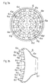
- Fig. 3 shows one example of the main comb block 6 constituting the attachment 4.
- a connection portion 6f for connection to the discharge section 8 of the hair dryer housing 3 is provided at the rear-end portion of a generally bell-mouthed cylindrical member 6e
- a recessed base block 6b is provided curving rearwardly at the front-end surface portion of the generally bell-mouthed cylindrical member 6e
- plural comb teeth 6a and blow-out holes 6d are provided in this curved base block 6b.
- the comb teeth 6a are formed to tube shapes, the rear-end portions of the tubular comb teeth 6a open in the generally bell-mouthed cylindrical member 6e, and holes 6g for passing through an air blow are provided in the tubular comb teeth 6a.
- the holes 6g for air blow passage which are provided in the comb teeth 6a are provided in side portions of the front halves of the comb teeth 6a, although they may also be provided in the front tip portions, central portions or lower edge portions of the comb teeth 6a.
- the blow-out holes 6d and the holes 6g here constitute blow-out sections 6c via which air is blown out.
- Fig. 4 shows one example of an auxiliary comb block 7.
- this auxiliary comb block 7 plural comb teeth 7a are provided projecting forwards at the front-surface portion of a base block 7b whose rear-end surface is made a curved surface like that of the front surface portion 6b of the main comb block 6, and plural blow-out holes 7d are provided in this base block 7b.
- the comb teeth 7a are formed to tube shapes, openings at the rear-end portions of the tubular comb teeth 7a open at the rear-surface side of the base block 7b, and holes 7g for passage of an air blow are provided in the tubular comb teeth 7a.
- These holes 7g for air passage which are provided in the comb teeth 7a are provided in side portions of the front halves of the comb teeth 7a in the attached drawings, although they may also be provided in the tip-end portions, central portions or lower-edge portions of the comb-teeth 7a.
- the blow-out holes 7d and the holes 7g here constitute blow-out sections 7c via which air is blown out.
- the plural comb teeth 7a provided on the base block 7b of the auxiliary comb block 7 are disposed in the same positional relations as the plural comb teeth 6a provided on the base block 6b of the main comb block 6.
- the plural holes 7g are so arranged that they are in the same positional relations as the plural holes 6g, or they are offset relative to the positions of the plural holes 6g, so that there is communication between one lot of holes 7g and one lot of holes 6g and no communication between the other lot of holes 7g and the other lot of holes 6g or so that there is communication between portions of the holes 7g and portions of the holes 6g.
- Suitably setting communication states in such a manner makes it possible for the air blow-out opening areas in the case in which the auxiliary comb block 7 is fitted to the main comb block 6 and in the case in which it is not fitted to be made the same or to be made different.
- the projection length of the comb teeth 7a is greater than that of the comb teeth 6a, and is made a magnitude such as to permit the tubular comb teeth 6a to be fitted in at the rear-end portion of the tubular comb teeth 7a.
- the rear end portion of the auxiliary comb block 7 is made such that it can be detachably fitted to the front-end portion of the main comb block 6, and, as shown in Fig. 1, in a state in which the rear-end portion of the auxiliary comb block 7 is detachably fitted to the front-end portion of the main comb block 6, the shorter comb teeth 6a fit inside the longer comb teeth 7a, and so are surrounded by the comb teeth 7a, and there is communication between the holes 7g and the holes 6g.
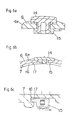
- Fig. 5 and Fig. 6 show one example of the locking structure for occasions when the rear-end portion of the auxiliary comb block 7 is fitted to the front-end portion of the main comb block 6.
- An actuation element 14 is mounted on the outer periphery portion of the front-end portion of the main comb block 6 in a manner such that it can slide peripherally, and this actuation element 14 is provided with an actuation lever 15 which has a retention portion 17 at the inner peripheral side of the main comb block 6.
- an engagement groove portion 16 is provided in a peripherally directed portion of the outer periphery portion of the rear-end portion of the auxiliary comb block 7.
- the rear-end portion of the auxiliary comb block 7 is fitted in the front-end portion of the main comb block 6, and, as the result of the actuation lever 15 being slid by sliding the actuation element 14, the retention portion 17 provided on the actuation lever 15 engages the engagement groove portion 16, so making it possible to effect locking as shown in Fig. 6(c).
- the retention portion 17 provided on the actuation lever 15 is moved away from the engagement groove portion 16, so releasing the lock, by effecting slide actuation of the actuation element 14 in the direction opposite to that described above and sliding the actuation lever 15 in the direction of the arrow in Fig. 6(c), and in this state, therefore, the auxiliary comb block 7 can be detached from the main comb block 6.
- a lock point with a lock structure such as described above is provided at one location or at plural locations in the peripheral direction.
- the state in which the auxiliary comb block 7 is fitted to the main comb block 6 as shown in Fig. 1 is a state in which the implement can be used as a hair dryer with a long comb, while the state in which the auxiliary comb block 7 is detached is one in which the implement can be used as a hair dryer with a short comb and so a hair dryer with different functions can be applied to respective different hair sets.
- the blow-out holes 7d and the holes 7g of the comb teeth 7a serve for hair drying and hair setting
- the blow-out holes 6d and the holes 6g of the comb teeth 6a serve for hair drying and hair setting.
- the plural blow-out holes 7d provided in the base block 7b of the auxiliary comb block 7 are so arrayed that they are in the same positional relations as the plural comb teeth 6a provided on the base block 6b of the main comb block 6, the comb teeth 6a are insertable in the blow-out holes 7d, the plural comb teeth 7a provided on the base block 7b of the auxiliary comb block 7 are so arrayed that they are in the same positional relations as the plural blow-out holes 6d provided in the base block 6b of the main comb block 6, and communication can be established between the rear-end openings of the comb teeth 7a and the blow-out holes 6d.
- a repeat description of the structure will be omitted.
- the comb teeth 6a of the main comb block 6 are inserted in the blow-out holes 7d of the auxiliary comb block 7 in the state in which the auxiliary comb block 7 is fitted to the main comb block 6, as shown in Fig. 8(c) (Fig. 7 shows the state immediately before the fitting together.)
- the comb teeth 6a and the comb teeth 7a project out at different positions, and so the number of comb teeth can be made greater than it is when the main comb block 6 is used without fitting the auxiliary comb block 7, and, when the number of comb teeth is thus increased by fitting on the auxiliary comb block 7, it is easy to entwine the hair and produce a hair set such as one in which the hair stands up from the roots.
- a hair dryer which has different numbers of comb teeth in the case in which the auxiliary comb block 7 is fitted and the case in which it is removed.
- a generally bell-mouthed cylindrical member 7e constituting a connection portion which can be fitted into an opening end portion at the front-end portion of a generally bell-mouthed cylindrical member 6e
- the front-end portion of the generally bell-mouthed cylindrical member 7e has a larger diameter than the connection portion at its rear-end portion, and, as the result of a base block 7b being provided in this larger-diameter front-end portion of the generally bell-mouthed cylindrical member 7e, the area of front-end portion of the base block 7b is greater than the area of the front-end portion of the main comb block 6.
- the area of the blow-out sections 7c (7d, 7g) of the auxiliary comb block 7 is larger than the area of the blow-out sections 6c (6d, 6g) of the main comb block 6.
- the air blow-out area is greater than it is with the main comb block 6 alone, and so the air blow speed fails and a gentle air blow is supplied, and, therefore, it is possible to effect gentle drying of the hair and produce a soft hair set.
- a repeat description thereof will be omitted.
- the auxiliary comb block 7 can be fitted in or removed from one region of the main comb block 6.
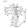
- the form of implementation shown in Fig. 10 illustrates an example in which the auxiliary comb block 7 is detachably fittable in half the region of the main comb block 6, although there is no restriction to just half the region but the auxiliary comb block 7 may be detachably fitted to a variety of locations, such as, eg, to the central region of the main comb block 6 as shown in Fig. 11, or to the outer periphery region of the main comb block 6 as shown in Fig. 12.
- a still further form of implementation of the invention will be described with reference to Fig. 13 and Fig. 14.
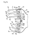
- This form of implementation is an example in which there are plural auxiliary comb blocks 7, and each of these auxiliary comb blocks 7 can be fitted to or removed from the main comb block 6.
- plural auxiliary comb blocks 7 (Fig. 13 and Fig. 14 show examples in which there are two, although there may be three or more) can be independently fitted to and removed from the main comb block 6.
- different forms of use such as that in the case in which only one out of the plural auxiliary comb blocks 7 is fitted to the main comb block 6 (the same as in Fig. 9), that in the case in which plural auxiliary comb blocks 7 are fitted as shown in Fig. 13, and that in the case in which no auxiliary comb block 7 is fitted, and the range of use is therefore greatly increased and the variety of hair set patterns can be increased.
- the device may be one which, as shown in Fig 14, is so formed that the comb tooth 7a shape of at least one auxiliary comb block 7 whithin the plural auxiliary comb blocks 7 is different from the comb tooth 7a shape of the other auxiliary comb blocks 7. With this device, it is possible to increase the number of hair set patterns still more.
Description
- The present invention relates to a hair dryer for drying hair.
- A hair dryer housing possessing an air delivery section and a heating section, and a hair dryer in which an attachment can be detachably fitted to the discharge section of the hair dryer housing are conventionally known.
- However, in a conventional hair dryer in which an attachment can be detachably fitted to the discharge section of the hair dryer housing, only a single attachment can be fitted to the hair dryer housing, and normally, therefore, when plural attachments are used for producing a hair style, it is necessary to change the various attachments and fit each of them to the hair dryer housing, which is inconvenient in terms of use, and is also inconvenient for tidying things away.
- The US 5,275,339 describes a diffuser for a hairdryer having an air discharge nozzle. The diffuser comprises a body having an air inlet being connectable to the hairdryer air outlet. The diffuser further comprises opposite to the air inlet a grill defining a plurality of discharge openings. Additionally, this portion includes a plurality of generally hollow fingers extending from the grill outwardly provided with openings radially to their longitudinal extension. These openings are also provided for discharging air.
- The present invention has been devised in view of the above noted problems of conventional examples, and it takes as its object the provision of a hair dryer in which, it is easy to adapt to plural applications with a single attachment, and which is also convenient in respect of tidying things away.
- The solution is based on the fact that an auxiliary comb block is detachably fitted to an attachment according to claim 1.
- In the invention of Claim 1, since, as described above, in a combination of a hair dryer and an attachment, constituted by a hair dryer housing possessing an air delivery section and a heating section and by an attachment which is fittable to a discharge section of the hair dryer housing, whereby said attachment is constituted by a combination of a main comb block possessing a comb, a base block and blow-out sections, and an auxiliary comb block consisting of a comb, a base block and blow-out sections which is detachably fittable to this said main comb block. It is possible to adapt to two different applications, which are that in the case in which, with a single attachment serving as a base, the hair dryer is used with the auxiliary comb block fitted to the attachment, and that in the case in which the hair dryer is used without fitting on the auxiliary comb block, and there is also the convenience that, in tidying away, the hair dryer can be tidied away as one unit by fitting the second comb block to the attachment.
- In the invention of
Claim 2, since the comb of the auxiliary comb block is formed to a tube shape and is so disposed that it surrounds the comb of the main comb block, the hair dryer is one which, in addition to the advantages of the invention of Claim 1, can be made a device with forms in which the comb lengths (heights) are different, depending whether the auxiliary comb block is not fitted to the main comb block or is fitted to the main comb block. - In the invention of
Claim 3, since blow-out holes are provided in at least one out of the comb and the base block of the main comb block, and blow-out holes which are in communication with the blow-out holes of the main comb block are provided in at least one out of the comb and the base block of the auxiliary comb block, the hair dryer is one which, in addition to the advantages of the invention of Claim 1, can be made a device with forms in which the comb lengths (heights) are made different, depending on whether the auxiliary comb block is fitted to the main comb block or is not fitted to the main comb block, but the air blow speed is not changed. - In the invention of Claim 4, since blow-out holes are provided in the base block of the auxiliary comb block and it is made possible to effect detachable fitting in a manner such that the comb of the main comb block is inserted through these blow-out holes, in addition to the advantages of the invention of Claim 1, it is possible to change the number of comb teeth, by fitting or not fitting the auxiliary comb block to the main comb block, and the device can be made convenient for hair arrangements by changing the number of comb teeth.
- In the invention of Claim 5 since the area of the blow-out sections of the auxiliary comb block is made greater than the area of the blow-out sections of the main comb block,
- in addition to the advantages of the invention of Claim 1, it is possible to reduce the air blow speed and increase the number of gentle drying patterns by fitting the auxiliary comb block to the main comb block.
- In the invention of
Claim 6, since the auxiliary comb block is fittable to and detachable from one region of the main comb block, in addition to the advantages of the invention of Claim 1, the device can produce hair sets such as ones with which there is gentle drying and the hair is caused to stand up from the roots and it can be used for a variety of different hair sets. - In the invention of
Claim 7, since there are plural auxiliary comb blocks and each of the plural auxiliary comb blocks is fittable to and detachable from the main comb block, in addition to the advantages of the invention of Claim 1, the device can be adapted to three or more hair sets. - In the invention of
Claim 8, since the shape of at least one auxiliary comb block is made different from the shape of other auxiliary comb blocks, in addition to the advantages of the invention of Claim 1, the number of hair set patterns can be increased still further. - Further features and advantages of the present invention will become obvious from the following description based on the drawings:
- Fig. 1
- This is a side cross-sectional view showing the overall structure of the hair dryer of the invention.
- Fig. 2
- This is a front view of the above.
- Fig. 3
- This shows the main comb block of the above, (a) being a front view, and (b) a cross-sectional view.
- Fig. 4
- This shows the auxiliary comb block of the above, (a) being a front view, and (b) a cross-sectional view.
- Fig. 5
- This is a side cross-sectional view of a lock mechanism of the above.
- Fig. 6
- This shows the lock mechanism of the above, (a) being an enlarged side cross-sectional view, (b) an enlarged front cross-sectional view, and (c) an enlarged plane cross-sectional view.
- Fig. 7
- This is a disassembly cross-sectional view of the main comb block and the auxiliary comb block in another form of implementation of the invention.
- Fig. 8
- (a) shows a front view of the auxiliary comb block of the above, (b) shows a front view of the main comb block, and (c) shows a front view of the state in which the auxiliary comb block is fitted to the main comb block.
- Fig. 9
- This is a cross-sectional view of a state in which an auxiliary comb block is fitted to the main comb block in a still further form of implementation of the invention.
- Fig. 10
- This is a cross-sectional view of a state in which an auxiliary comb block is fitted to the main comb block in a still further form of implementation of the invention.
- Fig. 11
- This is a cross-sectional view of another example of fitting of an auxiliary comb block to the main comb block of the above.
- Fig. 12
- This is a cross-sectional view of a further example of fitting of an auxiliary comb block to the main comb block of the above.
- Fig. 13
- This is a cross-sectional view of a state in which auxiliary comb blocks are fitted to the main comb block in a still further form of implementation of the invention.
- Fig. 14
- This is a cross-sectional view of another example of fitting of auxiliary comb blocks to the main comb block of the above.
- In order to resolve the problems noted above, the hair dryer of the present invention is one whose special feature is that, in a hair dryer 5 which is constituted by a
hair dryer housing 3 possessing an air delivery section 1 and aheating section 2, and by an attachment 4 which is fittable to thedischarge section 8 of thehair dryer housing 3, the attachment 4 is constituted by amain comb block 6 possessing acomb 6a, abase block 6b and blow-outsections 6c, and anauxiliary comb block 7 which consists of acomb 7a, abase block 7b and blow-outsections 7c, is detachably fitted to the attachment 4. When the structure is made thus, it is possible to adapt to different applications, which are that in the case in which, with a single attachment 4 serving as a base, the hair dryer is used with theauxiliary comb block 7 fitted to the attachment 4, and that in the case in which the hair dryer is used without fitting on theauxiliary comb block 7. Further, when the hair dryer is tidied away, it can be tidied away as one unit by fitting theauxiliary comb block 7 to the attachment 4. - Suitably, the
comb 7a of theauxiliary comb block 7 is formed to a tube shape, and surrounds thecomb 6a of themain comb block 6. When the structure is made thus, the device is one in which, with a single attachment 4 serving as a base, it is possible to change the comb length. - Suitably, blow-out
holes comb 6a andbase block 6b of themain comb block 6, and blow-outholes holes comb 7a andbase block 7b of theauxiliary comb block 7. When the structure is made thus, depending on whether the main comb block is used alone or the auxiliary comb block is fitted to the main comb block, it is possible to arrange and dry the hair while effecting blow-out of air from the blow-outholes 6d and/or 6g, or to arrange and dry the hair while effecting blow-out of air from the blow-outholes holes - Suitably, blow-out
holes 7d are provided in thebase block 7b of theauxiliary comb block 7, and it is made possible to effect detachable fitting in a manner such that thecomb 6a of themain comb block 6 is inserted through these blow-outholes 7d. When the structure is made thus, it is possible to change the number of comb teeth, depending on whether the device is used with themain comb block 6 alone or is used with theauxiliary comb block 7 fitted to themain comb block 6. - Suitably, the blow-out area of the blow-out
sections 7c of theauxiliary comb block 7 is made larger than the blow-out area of the blow-outsections 6c of themain comb block 6. When the structure is made thus, it is possible to reduce the air blow speed by fitting theauxiliary comb block 7 to themain comb block 6 and so effect gentle drying of the hair. - Suitably, the
auxiliary comb block 7 is made detachably fittable to one region of themain comb block 6. When the structure is made thus, fitting theauxiliary comb block 7 makes it possible to adapt to hair sets which comprise both gentle drying and a hair set in which the hair stands up from the roots. - Suitably, there are plural
auxiliary comb blocks 7 and they are each detachably fittable to themain comb block 6. When the structure is made thus, since there are plural auxiliary comb blocks, it is possible to produce three or more patterns for hair sets. - Suitably, the shape of the
comb 7a of at least oneauxiliary comb block 7 is made different from that of thecombs 7a of the otherauxiliary comb blocks 7. When the structure is made thus, it is possible to increase the number of hair set patterns. - An air delivery section 1 which consists of a fan 9 and a
motor 10 for producing an air blow in acylindrical barrel section 13, and aheating section 2 possessing a heater wire 11 for heating the air blow from air delivery section 1 are accommodated in ahair dryer housing 3, and there is also provided aswitching circuit section 12 for effecting changeover between various utilization modes. Adischarge section 8 for discharging warm air is provided at the front-end portion of thecylindrical barrel section 13 of thehair dryer housing 3. - An attachment 4 is fitted to the
discharge section 8 of thehair dryer housing 3. The example illustrated in the form of implementation which is shown in the attached drawings is the case in which the attachment 4 is amain comb block 6. - Fig. 3 shows one example of the
main comb block 6 constituting the attachment 4. In themain comb block 6, aconnection portion 6f for connection to thedischarge section 8 of thehair dryer housing 3 is provided at the rear-end portion of a generally bell-mouthedcylindrical member 6e, a recessedbase block 6b is provided curving rearwardly at the front-end surface portion of the generally bell-mouthedcylindrical member 6e, andplural comb teeth 6a and blow-outholes 6d are provided in thiscurved base block 6b. Thecomb teeth 6a are formed to tube shapes, the rear-end portions of thetubular comb teeth 6a open in the generally bell-mouthedcylindrical member 6e, and holes 6g for passing through an air blow are provided in thetubular comb teeth 6a. Theholes 6g for air blow passage which are provided in thecomb teeth 6a are provided in side portions of the front halves of thecomb teeth 6a, although they may also be provided in the front tip portions, central portions or lower edge portions of thecomb teeth 6a. The blow-outholes 6d and theholes 6g here constitute blow-outsections 6c via which air is blown out. - Fig. 4 shows one example of an
auxiliary comb block 7. In thisauxiliary comb block 7,plural comb teeth 7a are provided projecting forwards at the front-surface portion of abase block 7b whose rear-end surface is made a curved surface like that of thefront surface portion 6b of themain comb block 6, and plural blow-outholes 7d are provided in thisbase block 7b. Thecomb teeth 7a are formed to tube shapes, openings at the rear-end portions of thetubular comb teeth 7a open at the rear-surface side of thebase block 7b, and holes 7g for passage of an air blow are provided in thetubular comb teeth 7a. Theseholes 7g for air passage which are provided in thecomb teeth 7a are provided in side portions of the front halves of thecomb teeth 7a in the attached drawings, although they may also be provided in the tip-end portions, central portions or lower-edge portions of the comb-teeth 7a. The blow-outholes 7d and theholes 7g here constitute blow-outsections 7c via which air is blown out. - In the form of implementation shown in Figs. 1-4, the
plural comb teeth 7a provided on thebase block 7b of theauxiliary comb block 7 are disposed in the same positional relations as theplural comb teeth 6a provided on thebase block 6b of themain comb block 6. Theplural holes 7g are so arranged that they are in the same positional relations as theplural holes 6g, or they are offset relative to the positions of theplural holes 6g, so that there is communication between one lot ofholes 7g and one lot ofholes 6g and no communication between the other lot ofholes 7g and the other lot ofholes 6g or so that there is communication between portions of theholes 7g and portions of theholes 6g. Suitably setting communication states in such a manner makes it possible for the air blow-out opening areas in the case in which theauxiliary comb block 7 is fitted to themain comb block 6 and in the case in which it is not fitted to be made the same or to be made different. The projection length of thecomb teeth 7a is greater than that of thecomb teeth 6a, and is made a magnitude such as to permit thetubular comb teeth 6a to be fitted in at the rear-end portion of thetubular comb teeth 7a. - The rear end portion of the
auxiliary comb block 7 is made such that it can be detachably fitted to the front-end portion of themain comb block 6, and, as shown in Fig. 1, in a state in which the rear-end portion of theauxiliary comb block 7 is detachably fitted to the front-end portion of themain comb block 6, theshorter comb teeth 6a fit inside thelonger comb teeth 7a, and so are surrounded by thecomb teeth 7a, and there is communication between theholes 7g and theholes 6g. - Fig. 5 and Fig. 6 show one example of the locking structure for occasions when the rear-end portion of the
auxiliary comb block 7 is fitted to the front-end portion of themain comb block 6. Anactuation element 14 is mounted on the outer periphery portion of the front-end portion of themain comb block 6 in a manner such that it can slide peripherally, and thisactuation element 14 is provided with anactuation lever 15 which has aretention portion 17 at the inner peripheral side of themain comb block 6. Further, anengagement groove portion 16 is provided in a peripherally directed portion of the outer periphery portion of the rear-end portion of theauxiliary comb block 7. The rear-end portion of theauxiliary comb block 7 is fitted in the front-end portion of themain comb block 6, and, as the result of theactuation lever 15 being slid by sliding theactuation element 14, theretention portion 17 provided on theactuation lever 15 engages theengagement groove portion 16, so making it possible to effect locking as shown in Fig. 6(c). To effect detachment, theretention portion 17 provided on theactuation lever 15 is moved away from theengagement groove portion 16, so releasing the lock, by effecting slide actuation of theactuation element 14 in the direction opposite to that described above and sliding theactuation lever 15 in the direction of the arrow in Fig. 6(c), and in this state, therefore, theauxiliary comb block 7 can be detached from themain comb block 6. A lock point with a lock structure such as described above is provided at one location or at plural locations in the peripheral direction. - The state in which the
auxiliary comb block 7 is fitted to themain comb block 6 as shown in Fig. 1 is a state in which the implement can be used as a hair dryer with a long comb, while the state in which theauxiliary comb block 7 is detached is one in which the implement can be used as a hair dryer with a short comb and so a hair dryer with different functions can be applied to respective different hair sets. When theauxiliary comb block 7 is fitted on, the blow-outholes 7d and theholes 7g of thecomb teeth 7a serve for hair drying and hair setting and when theauxiliary comb block 7 is detached, the blow-outholes 6d and theholes 6g of thecomb teeth 6a serve for hair drying and hair setting. - Next, another form of implementation of the invention will be described with reference to Fig. 7 and Fig. 8. The form of implementation described above gave an example in which the
plural comb teeth 7a and theplural comb teeth 6a are so arrayed that they are in the same positional relations, whereas in this form of implementation, as shown in Figs. 8(a) and (b), the plural blow-outholes 7d provided in thebase block 7b of theauxiliary comb block 7 are so arrayed that they are in the same positional relations as theplural comb teeth 6a provided on thebase block 6b of themain comb block 6, thecomb teeth 6a are insertable in the blow-outholes 7d, theplural comb teeth 7a provided on thebase block 7b of theauxiliary comb block 7 are so arrayed that they are in the same positional relations as the plural blow-outholes 6d provided in thebase block 6b of themain comb block 6, and communication can be established between the rear-end openings of thecomb teeth 7a and the blow-outholes 6d. As other parts of the structure are the same as in the form of implementation described earlier, a repeat description of the structure will be omitted. - In this form of implementation, since the
comb teeth 6a of themain comb block 6 are inserted in the blow-outholes 7d of theauxiliary comb block 7 in the state in which theauxiliary comb block 7 is fitted to themain comb block 6, as shown in Fig. 8(c) (Fig. 7 shows the state immediately before the fitting together.), thecomb teeth 6a and thecomb teeth 7a project out at different positions, and so the number of comb teeth can be made greater than it is when themain comb block 6 is used without fitting theauxiliary comb block 7, and, when the number of comb teeth is thus increased by fitting on theauxiliary comb block 7, it is easy to entwine the hair and produce a hair set such as one in which the hair stands up from the roots. Thus, in this form of implementation, it is possible to adopt to different hair sets with a hair dryer which has different numbers of comb teeth in the case in which theauxiliary comb block 7 is fitted and the case in which it is removed. - Next, another form of implementation of the invention will be described with reference to Fig. 9. In this form of implementation, at the rear-end portion of the
auxiliary comb block 7, there is a generally bell-mouthed cylindrical member 7e constituting a connection portion which can be fitted into an opening end portion at the front-end portion of a generally bell-mouthedcylindrical member 6e, the front-end portion of the generally bell-mouthed cylindrical member 7e has a larger diameter than the connection portion at its rear-end portion, and, as the result of abase block 7b being provided in this larger-diameter front-end portion of the generally bell-mouthed cylindrical member 7e, the area of front-end portion of thebase block 7b is greater than the area of the front-end portion of themain comb block 6. Further, the area of the blow-outsections 7c (7d, 7g) of theauxiliary comb block 7 is larger than the area of the blow-outsections 6c (6d, 6g) of themain comb block 6. When theauxiliary comb block 7 is fitted to themain comb block 6 in the manner shown in Fig. 9, the air blow-out area is greater than it is with themain comb block 6 alone, and so the air blow speed fails and a gentle air blow is supplied, and, therefore, it is possible to effect gentle drying of the hair and produce a soft hair set. As the structure in this form of implementation apart from that described above is like that of the form of implementation shown in Fig. 1, a repeat description thereof will be omitted. - Next, a still further form of implementation will be described with reference to Figs. 10-12. In this form of implementation, the
auxiliary comb block 7 can be fitted in or removed from one region of themain comb block 6. The form of implementation shown in Fig. 10 illustrates an example in which theauxiliary comb block 7 is detachably fittable in half the region of themain comb block 6, although there is no restriction to just half the region but theauxiliary comb block 7 may be detachably fitted to a variety of locations, such as, eg, to the central region of themain comb block 6 as shown in Fig. 11, or to the outer periphery region of themain comb block 6 as shown in Fig. 12. This makes it possible to adapt to a variety of hair sets, such as ones with which there is gentle drying and the hair is caused to stand up from the roots. As the structure in this form of implementation apart from that described above is like that of the form of implementation shown in Fig. 1, a repeat description thereof will be omitted. - Next, a still further form of implementation of the invention will be described with reference to Fig. 13 and Fig. 14. This form of implementation is an example in which there are plural auxiliary comb blocks 7, and each of these auxiliary comb blocks 7 can be fitted to or removed from the
main comb block 6. More specifically, plural auxiliary comb blocks 7 (Fig. 13 and Fig. 14 show examples in which there are two, although there may be three or more) can be independently fitted to and removed from themain comb block 6. As a result, it is possible to select different forms of use (at least three different forms of use) such as that in the case in which only one out of the plural auxiliary comb blocks 7 is fitted to the main comb block 6 (the same as in Fig. 9), that in the case in which plural auxiliary comb blocks 7 are fitted as shown in Fig. 13, and that in the case in which noauxiliary comb block 7 is fitted, and the range of use is therefore greatly increased and the variety of hair set patterns can be increased. - Further the device may be one which, as shown in Fig 14, is so formed that the
comb tooth 7a shape of at least oneauxiliary comb block 7 whithin the plural auxiliary comb blocks 7 is different from thecomb tooth 7a shape of the other auxiliary comb blocks 7. With this device, it is possible to increase the number of hair set patterns still more. -
- 1
- Air delivery section
- 2
- Heater section
- 3
- Hair dryer housing
- 4
- Attachment
- 5
- Hair dryer
- 6
- Main comb block
- 6a
- Comb tooth
- 6d
- Blow-out hole
- 7
- Auxiliary comb block
- 7a
- Comb tooth
- 7b
- Base block
- 7c
- Blow-out section
- 7d
- Blow-out hole
- 8
- Discharge section
Claims (8)
- A combination of a hair dryer (5) and an attachment (4), constituted by a hair dryer housing (3) possessing an air delivery section (1) and a heating section (2) and by an attachment (4) which is fittable to a discharge section (8) of the hair dryer housing (3), characterized in that said attachment is constituted by a combination of a main comb block (6) possessing a comb (6a), a base block (6b) and blow-out sections (6c) and an auxiliary comb block (7) consisting of a comb (7a), a base block (7b) and blow-out sections (7c), which is detachably fittable to this said main comb block (6).
- A combination of a hair dryer (5) and an attachment (4) as claimed in Claim 1 wherein the comb (7a) of the auxiliary comb block (7) is formed to a tube shape and is so disposed that it surrounds the comb of the main comb block.
- A combination of a hair dryer (5) and an attachment (4) as claimed in Claim 1 wherein blow-out holes (6d, 6g) are provided in at least one out of the comb and the base block of the main comb block, and blow-out holes (7d, 7g) which are in communication with the blow-out holes of the main comb block are provided in at least one out of the comb and the base block of the auxiliary comb block.
- A combination of a hair dryer (5) and an attachment (4) as claimed in Claim 1 wherein blow-out holes (7d) are provided in the base block of the auxiliary comb block, and it is made possible to effect detachable fitting in a manner such that the comb of the main comb block is inserted through these blow-out holes.
- A combination of a hair dryer (5) and an attachment (4) as claimed in Claim 1 wherein the area of the blow-out sections (7c) of the auxiliary comb block is made greater than the area of the blow-out sections (6c) of the main comb block.
- A combination of a hair dryer (5) and an attachment (4) as claimed in Claim 1 wherein the auxiliary comb block is fittable to and detachable from one region of the main comb block.
- A combination of a hair dryer (5) and an attachment (4) as claimed in Claim 1 wherein there are plural auxiliary comb blocks and each of the plural auxiliary comb blocks is fittable to and detachable from the main comb block.
- A combination of a hair dryer (5) and an attachment (4) as claimed in Claim 7 wherein the shape of at least one auxiliary comb block is made different from the shape of other auxiliary comb blocks.
Applications Claiming Priority (2)
| Application Number | Priority Date | Filing Date | Title |
|---|---|---|---|
| JP04577898A JP3855435B2 (en) | 1998-02-26 | 1998-02-26 | Hair dryer |
| JP4577898 | 1998-02-26 |
Publications (3)
| Publication Number | Publication Date |
|---|---|
| EP0940101A2 EP0940101A2 (en) | 1999-09-08 |
| EP0940101A3 EP0940101A3 (en) | 1999-12-08 |
| EP0940101B1 true EP0940101B1 (en) | 2003-09-24 |
Family
ID=12728761
Family Applications (1)
| Application Number | Title | Priority Date | Filing Date |
|---|---|---|---|
| EP99103630A Expired - Lifetime EP0940101B1 (en) | 1998-02-26 | 1999-02-25 | Hairdryer |
Country Status (3)
| Country | Link |
|---|---|
| EP (1) | EP0940101B1 (en) |
| JP (1) | JP3855435B2 (en) |
| DE (1) | DE69911484T2 (en) |
Cited By (3)
| Publication number | Priority date | Publication date | Assignee | Title |
|---|---|---|---|---|
| US10660418B2 (en) | 2017-07-14 | 2020-05-26 | Spectrum Brands, Inc. | Air-moving appliance including an attachment |
| US10835007B2 (en) | 2017-07-14 | 2020-11-17 | Spectrum Brands, Inc. | Hair dryer |
| US11363871B2 (en) | 2016-09-19 | 2022-06-21 | Diversame, Inc. | Hair styling device |
Families Citing this family (13)
| Publication number | Priority date | Publication date | Assignee | Title |
|---|---|---|---|---|
| GB2413073A (en) * | 2004-04-14 | 2005-10-19 | Kenford Ind Co Ltd | Nozzle having thermal capacitance element |
| GB2414180B (en) * | 2004-05-21 | 2007-07-25 | Kenford Ind Co Ltd | Hairdryer diffuser |
| JP4663466B2 (en) * | 2005-09-27 | 2011-04-06 | 三洋電機株式会社 | Hair dryer |
| US8407913B2 (en) * | 2007-09-27 | 2013-04-02 | Wahl Clipper Corporation | Conditioner infuser for hair dryer attachment |
| GB2539441B (en) | 2015-06-16 | 2019-01-09 | Dyson Technology Ltd | Diffuser |
| EP3106058A1 (en) | 2015-06-16 | 2016-12-21 | Dyson Technology Limited | Diffuser |
| GB2539432B (en) | 2015-06-16 | 2019-01-09 | Dyson Technology Ltd | Diffuser |
| WO2016203196A1 (en) | 2015-06-16 | 2016-12-22 | Dyson Technology Limited | Diffuser |
| GB2539431B (en) | 2015-06-16 | 2018-01-03 | Dyson Technology Ltd | Diffuser |
| GB2539437B (en) * | 2015-06-16 | 2018-07-04 | Dyson Technology Ltd | Diffuser |
| DE102018004605B4 (en) | 2018-06-11 | 2022-09-01 | Felix Müller | Fan attachment to optimize mix ventilation |
| GB2602091B (en) * | 2020-12-17 | 2023-10-11 | Dyson Technology Ltd | Diffuser |
| GB2623576A (en) * | 2022-10-21 | 2024-04-24 | Dyson Technology Ltd | Attachment for a haircare appliance |
Citations (1)
| Publication number | Priority date | Publication date | Assignee | Title |
|---|---|---|---|---|
| US5715847A (en) * | 1994-12-17 | 1998-02-10 | Braun Aktiengesellschaft | Hair styling implement |
Family Cites Families (5)
| Publication number | Priority date | Publication date | Assignee | Title |
|---|---|---|---|---|
| DE2529809A1 (en) * | 1975-07-04 | 1977-01-27 | Bruno Dr Theves | Quick drying hair dryer - has hollow toothed comb attachment to direct air upwards through hair enabling use of higher air temperature |
| GB9124609D0 (en) * | 1991-11-20 | 1992-01-08 | Parkinson James W | A diffuser |
| US5235759A (en) * | 1992-08-25 | 1993-08-17 | Conair Corporation | Reversible diffuser for hair dryer |
| US5275339A (en) * | 1992-12-10 | 1994-01-04 | Andis Company | Diffuser for hair dryer |
| US5725895B1 (en) * | 1995-09-15 | 2000-10-10 | Hopkins J School Of Medicine | Method of preparing food product from cruciferous seeds |
-
1998
- 1998-02-26 JP JP04577898A patent/JP3855435B2/en not_active Expired - Fee Related
-
1999
- 1999-02-25 EP EP99103630A patent/EP0940101B1/en not_active Expired - Lifetime
- 1999-02-25 DE DE69911484T patent/DE69911484T2/en not_active Expired - Lifetime
Patent Citations (1)
| Publication number | Priority date | Publication date | Assignee | Title |
|---|---|---|---|---|
| US5715847A (en) * | 1994-12-17 | 1998-02-10 | Braun Aktiengesellschaft | Hair styling implement |
Cited By (5)
| Publication number | Priority date | Publication date | Assignee | Title |
|---|---|---|---|---|
| US11363871B2 (en) | 2016-09-19 | 2022-06-21 | Diversame, Inc. | Hair styling device |
| US10660418B2 (en) | 2017-07-14 | 2020-05-26 | Spectrum Brands, Inc. | Air-moving appliance including an attachment |
| US10835007B2 (en) | 2017-07-14 | 2020-11-17 | Spectrum Brands, Inc. | Hair dryer |
| US11311090B2 (en) | 2017-07-14 | 2022-04-26 | Spectrum Brands, Inc. | Hair dryer |
| US11330884B2 (en) | 2017-07-14 | 2022-05-17 | Spectrum Brands, Inc. | Air-moving appliance including an attachment |
Also Published As
| Publication number | Publication date |
|---|---|
| JPH11244032A (en) | 1999-09-14 |
| DE69911484T2 (en) | 2004-08-26 |
| EP0940101A2 (en) | 1999-09-08 |
| DE69911484D1 (en) | 2003-10-30 |
| EP0940101A3 (en) | 1999-12-08 |
| JP3855435B2 (en) | 2006-12-13 |
Similar Documents
| Publication | Publication Date | Title |
|---|---|---|
| EP0940101B1 (en) | Hairdryer | |
| US11877638B2 (en) | Air-moving appliance including an attachment | |
| EP0468725B1 (en) | Air diffusers | |
| US4827105A (en) | Hand held hair dryer | |
| US6067724A (en) | Interchangeable brush head hair dryer | |
| US20110296705A1 (en) | Nozzle for blow dryer | |
| US6094837A (en) | Multi-functional hand-held hair dryer | |
| EP3530139B1 (en) | Hairdressing apparatus | |
| US5457894A (en) | Implement for styling/drying hair for an air-moving appliance for personal use | |
| US5845656A (en) | Appliance for hair styling and/or hair drying | |
| WO2003030675A8 (en) | Hair care attachments and devices | |
| EP1721541A2 (en) | Hair dryer attachment with axial and radial flow | |
| US11832701B2 (en) | Hair dryer attachment | |
| CN112790499A (en) | Multi-nozzle attachment for hair dryer | |
| EP0892614B1 (en) | Hair styling instrument | |
| CN117956923A (en) | Hair diffuser | |
| JP2011217996A (en) | Hair dryer | |
| CN113545586A (en) | Head-replaceable hair drier | |
| JPS6130561B2 (en) | ||
| US5983517A (en) | Hair drying and styling appliance | |
| JPH0148002B2 (en) | ||
| CN215583360U (en) | Head-replaceable hair drier | |
| CA2083086A1 (en) | Air-blower/vacuum attachment | |
| CN110638182A (en) | Deep hair care implement | |
| JPH11123107A (en) | Hair drier |
Legal Events
| Date | Code | Title | Description |
|---|---|---|---|
| PUAI | Public reference made under article 153(3) epc to a published international application that has entered the european phase |
Free format text: ORIGINAL CODE: 0009012 |
|
| AK | Designated contracting states |
Kind code of ref document: A2 Designated state(s): DE FR IT |
|
| AX | Request for extension of the european patent |
Free format text: AL;LT;LV;MK;RO;SI |
|
| PUAL | Search report despatched |
Free format text: ORIGINAL CODE: 0009013 |
|
| AK | Designated contracting states |
Kind code of ref document: A3 Designated state(s): AT BE CH CY DE DK ES FI FR GB GR IE IT LI LU MC NL PT SE |
|
| AX | Request for extension of the european patent |
Free format text: AL;LT;LV;MK;RO;SI |
|
| 17P | Request for examination filed |
Effective date: 20000419 |
|
| AKX | Designation fees paid |
Free format text: DE FR IT |
|
| RIN1 | Information on inventor provided before grant (corrected) |
Inventor name: IKADAI, KAZUYASU Inventor name: SAKAMOTO, TOSHIHIRO |
|
| RIN1 | Information on inventor provided before grant (corrected) |
Inventor name: IKADAI, KAZUYASU Inventor name: SAKAMOTO, TOSHIHIRO |
|
| 17Q | First examination report despatched |
Effective date: 20020806 |
|
| GRAH | Despatch of communication of intention to grant a patent |
Free format text: ORIGINAL CODE: EPIDOS IGRA |
|
| GRAS | Grant fee paid |
Free format text: ORIGINAL CODE: EPIDOSNIGR3 |
|
| GRAA | (expected) grant |
Free format text: ORIGINAL CODE: 0009210 |
|
| AK | Designated contracting states |
Kind code of ref document: B1 Designated state(s): DE FR IT |
|
| REF | Corresponds to: |
Ref document number: 69911484 Country of ref document: DE Date of ref document: 20031030 Kind code of ref document: P |
|
| ET | Fr: translation filed | ||
| PLBE | No opposition filed within time limit |
Free format text: ORIGINAL CODE: 0009261 |
|
| STAA | Information on the status of an ep patent application or granted ep patent |
Free format text: STATUS: NO OPPOSITION FILED WITHIN TIME LIMIT |
|
| 26N | No opposition filed |
Effective date: 20040625 |
|
| REG | Reference to a national code |
Ref country code: FR Ref legal event code: D6 |
|
| PGFP | Annual fee paid to national office [announced via postgrant information from national office to epo] |
Ref country code: IT Payment date: 20120213 Year of fee payment: 14 |
|
| PGFP | Annual fee paid to national office [announced via postgrant information from national office to epo] |
Ref country code: DE Payment date: 20130220 Year of fee payment: 15 Ref country code: FR Payment date: 20130301 Year of fee payment: 15 |
|
| PG25 | Lapsed in a contracting state [announced via postgrant information from national office to epo] |
Ref country code: IT Free format text: LAPSE BECAUSE OF NON-PAYMENT OF DUE FEES Effective date: 20130225 |
|
| REG | Reference to a national code |
Ref country code: DE Ref legal event code: R119 Ref document number: 69911484 Country of ref document: DE |
|
| REG | Reference to a national code |
Ref country code: FR Ref legal event code: ST Effective date: 20141031 |
|
| REG | Reference to a national code |
Ref country code: DE Ref legal event code: R119 Ref document number: 69911484 Country of ref document: DE Effective date: 20140902 |
|
| PG25 | Lapsed in a contracting state [announced via postgrant information from national office to epo] |
Ref country code: DE Free format text: LAPSE BECAUSE OF NON-PAYMENT OF DUE FEES Effective date: 20140902 Ref country code: FR Free format text: LAPSE BECAUSE OF NON-PAYMENT OF DUE FEES Effective date: 20140228 |