EP0940033B1 - Method of processing a video stream - Google Patents
Method of processing a video stream Download PDFInfo
- Publication number
- EP0940033B1 EP0940033B1 EP97913054A EP97913054A EP0940033B1 EP 0940033 B1 EP0940033 B1 EP 0940033B1 EP 97913054 A EP97913054 A EP 97913054A EP 97913054 A EP97913054 A EP 97913054A EP 0940033 B1 EP0940033 B1 EP 0940033B1
- Authority
- EP
- European Patent Office
- Prior art keywords
- frames
- pairs
- change
- interframe difference
- pair
- Prior art date
- Legal status (The legal status is an assumption and is not a legal conclusion. Google has not performed a legal analysis and makes no representation as to the accuracy of the status listed.)
- Expired - Lifetime
Links
- 238000000034 method Methods 0.000 title claims description 42
- 230000008859 change Effects 0.000 claims description 50
- 238000001514 detection method Methods 0.000 claims description 25
- 230000002123 temporal effect Effects 0.000 claims description 8
- 230000001419 dependent effect Effects 0.000 claims description 4
- 230000009467 reduction Effects 0.000 claims description 2
- 230000001131 transforming effect Effects 0.000 claims 1
- 230000008569 process Effects 0.000 description 14
- 230000009471 action Effects 0.000 description 5
- 239000013256 coordination polymer Substances 0.000 description 2
- 238000010586 diagram Methods 0.000 description 1
- 230000007774 longterm Effects 0.000 description 1
- 238000012544 monitoring process Methods 0.000 description 1
- 230000011218 segmentation Effects 0.000 description 1
- 238000004513 sizing Methods 0.000 description 1
- 230000026676 system process Effects 0.000 description 1
- 230000009466 transformation Effects 0.000 description 1
- 230000000007 visual effect Effects 0.000 description 1
Images


Classifications
-
- H—ELECTRICITY
- H04—ELECTRIC COMMUNICATION TECHNIQUE
- H04N—PICTORIAL COMMUNICATION, e.g. TELEVISION
- H04N5/00—Details of television systems
- H04N5/14—Picture signal circuitry for video frequency region
- H04N5/147—Scene change detection
-
- H—ELECTRICITY
- H04—ELECTRIC COMMUNICATION TECHNIQUE
- H04N—PICTORIAL COMMUNICATION, e.g. TELEVISION
- H04N19/00—Methods or arrangements for coding, decoding, compressing or decompressing digital video signals
- H04N19/50—Methods or arrangements for coding, decoding, compressing or decompressing digital video signals using predictive coding
- H04N19/503—Methods or arrangements for coding, decoding, compressing or decompressing digital video signals using predictive coding involving temporal prediction
-
- H—ELECTRICITY
- H04—ELECTRIC COMMUNICATION TECHNIQUE
- H04N—PICTORIAL COMMUNICATION, e.g. TELEVISION
- H04N5/00—Details of television systems
- H04N5/14—Picture signal circuitry for video frequency region
- H04N5/144—Movement detection
Definitions
- This invention relates to a method of processing a video stream, to detect changes, for example, a cut in scenes.
- a video stream consists of a number of frames that are displayed successively to create the illusion of motion.
- a sequence of frames can be considered to form a "scene", which is considered to be a continuous action in space and time (i.e. with no camera breaks).
- a "cut” is a discontinuity between scenes. A cut is sharp if it can be located between two frames and gradual if it takes place over a sequence of frames.
- a keyframe is a frame that represents a whole scene. It can either be calculated or selected from the frames of the scene it represents.
- Video parameters include intensity, red-green-blue (RGB), hue-value-chroma (HVC), and a motion vector.
- RGB red-green-blue
- HVC hue-value-chroma
- a traditional approach for detecting a cut is to compare one or more of these parameters, such as intensity, of the corresponding pixels in a pair of consecutive frames. If the number of pixels whose intensity values have changed from one frame to the next exceeds a certain threshold, a cut is presumed.
- False cuts may result from camera operations, object movements or flashes within a video clip, while missed cuts may result from gradual scene changes.
- EP-A-659 016 describes a cut detection method wherein a scene changing ratio is computed taking into account the frame difference between temporally spaced images as well as temporally successive images.
- EP-A-660327 describes a method for detecting abrupt and gradual scene changes wherein matching is performed between a current frame and a D th previous frame. Neither of these patents satisfactorily solves the problems outlined above.
- An object of the invention is to alleviate the afore-mentioned problems.
- a method of processing a video stream comprising the steps of selecting first pairs of frames in the video stream with a predetermined temporal spacing; selecting second pairs of frames in the video stream, said second pairs of frames having a longer temporal spacing than said first pairs of frames; for each of said first and second pairs of frames, determining a difference value representing the degree of change between the first and second frames of the pair and generating a particular logic level depending on whether this difference value exceeds a predetermined threshold; characterized in that the change in interframe difference value for successive pairs of frames is determined for each of said first and second pairs of frames and compared with a threshold to generate additional logic levels dependent on the change in interframe difference values for said successive frame pairs; and the generated logic levels are compared with a decision map to identify cuts in the video stream.
- the degree of change may be represented by the number of pixels for which a particular value, such as intensity, has changed.
- the difference value may be arrived at by, for example, taking the root mean square of the differences in pixel values. In this case, the difference in intensity value of each corresponding pair of pixels is determined, the results squared, and the square root taken of the sum. This rms value can then be compared to a threshold. A value other than intensity, for example hue, can be chosen for the value.
- the change in difference value between each of the first and second pairs of frames and the corresponding previous pairs is determined, and additional logic levels are generated that depend on whether the change in difference values exceeds a predetermined threshold.
- the additional logic levels are also compared with the decision map to assist in identifying the cuts. This additional step enhances the detection process.
- the invention also provides video processing apparatus comprising means for selecting first pairs of frames in the video stream with a predetermined temporal spacing; means for selecting second pairs of frames in the video stream, said second pairs of frames having a longer temporal spacing than said first pairs of frames; means for determining, for each of said first and second pairs of frames, a difference value representing the degree of change between the first and second frames of the pair and generating a particular logic level depending on whether this difference value exceeds a predetermined threshold; characterized in that it further comprises means for computing the change in interframe difference value for successive pairs of frames for each of said first and second pairs of frames and comparing said change with a threshold to generate additional logic levels dependent on the change in interframe difference values for said successive frame pairs; and means for comparing the generated logic levels with a decision map to identify cuts in the video stream.
- the system illustrated is typically implemented on a Pentium 133 MHz computer.
- a digital video stream for example, from a digital video camera or an analog feed passed through an analog-to-digital converter (not shown), is split and passed to short and long period units 1, 2.
- the short period comparison unit 1 identifies a pair of frames in a stream, for example, the fourth and fifth frames, and determines the number of pixels whose values have changed. This number is then compared with a threshold and allocated a logic level 1 if it exceeds the threshold and otherwise a logic level 0.
- the pixel values can be any suitable value, but typically the intensity is used.
- the long period comparison unit 2 carries out the same operation, except on pairs of frames that are temporally further apart, for example, first and eighth frames in the video stream. It generates a logical 1 if the number of pixels whose intensity values have changed exceeds a predetermined threshold. Otherwise it generates a logical 0.
- the video stream is then passed to the short period change detection unit 3 and the long period change detection unit 4.
- the short period change detection unit 3 compares the current interframe difference value, derived in unit 1, namely the number of pixels whose intensity values have changed between each pair of pixels, with the previous pair, or the average of all the previous pairs, of interframe difference values to derive the change. If the change in interframe difference values exceeds a predetermined threshold, a logical 1 is generated, otherwise a logical 0 is generated.
- the long period change detection unit 4 does the same as the short period change detection unit, except with frames separated by a longer period, the first and eighth frames in this example.
- the threshold for the long period change detection unit is typically higher than for the short period detection unit.
- a 1 means that unit 3 detects a change in difference values between successive pairs of frames above a threshold
- 0 means any change was below the threshold
- X means that the outcome of the short change comparison is not relevant to the decision.
- the system shown in Figure 1 moves through successive frames as follows. For example, if the system processes six frames at a time, frames 1 and 6 would form the long pair and frames 3 and 4 might form the short pair. If no cuts are detected in this block, the next block will be made of frames 2 to 7, with frames 2 and 7 forming the long pair, and frames 4 and 5 forming the short pair and so on. However, if a cut is detected, the next block will contain frames 6 to 11 since the block size is very small compared to a typical scene length and no two cuts can be detected within one block.
- a frame may contain one or more windows to which the above described process can be applied.
- the use of windows allows the system to focus on specific areas of a frame instead of considering the frame as a whole. This can save considerable processing time.
- the main processing routine is shown in Figure 2. Starting at block 10, the routine determines at process block 11 whether the frame is decompressed. If not, it is decompressed in process block 12. At process block 13, the frame number is incremented. Decision block 14 determines whether variable jump (set in the Tag routine to be described) is greater than 0 and the number of sectors is greater than 1. If not, and the FrameNo variable is greater than the Blocksize variable, block 15 calls the call detection routine shown in Figure 3. If the output of Decision block 14 is true, block 16 decrements the jump variable.
- variable jump set in the Tag routine to be described
- Figure 3 shows the cut detection routine. Starting from process block 21, block 22 performs the short frame comparison and block 23 performs the long frame comparison to determine the number of pixels whose intensity values have changed for each pair frames.
- Process blocks 27, 28 determine whether the percentage change is above the threshold for the associated window, and if so generate a logical 1, otherwise they generate a logical zero.
- Process blocks 25 and 26 perform the short and long change detection operations following which block 29 calls the set tag routine described with reference to Figure 4.
- Process block 30 causes the routine to loop for all windows of interest assuming the system is operating on the basis that there is more than one window. Of course, there could only be one window that represents a whole frame.
- Figure 4 shows the compare frames routine in more detail. Processing blocks 40, 41 loop for all the pixels in a row and column respectively. Block 42 then finds the differences between the corresponding pixels in the first and second frames of each pair. If the decision unit 43 finds a difference greater than a threshold, the CP variable, which represents the percentage change of the window containing the pixels is incremented.
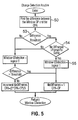
- Figure 5 shows the change detection routine identified in blocks 25, 26 in Figure 3 in more detail.
- Block 50 finds the difference between the change period CP for the window and the average change period CPA. If this change is greater than a threshold, as determined in decision unit 53, and the condition in block 54 is met, process block 55 sets the output to logical 1 to indicate a change.
- the change detection routine shown in Figure 5 works for both long period and short period changes.
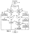
- the tag routine essentially implements the decision map table shown in Figure 7. Starting from process block 60 called by process block 29 in Figure 3, the routine determines whether there has been a short period change in block 61. If yes, decision block 63 determines whether there has been a short period cut, long period cut, and long period change. If yes, the block 67 creates a cut tag. If no, the block 68 determines whether there has been long period cut. If no, block 71 creates a flash tag.
- block 69 checks the condition !SPcut, and LPcut and LPchange is met, where !SPcut means that the SPcut variable is logical 0, or in other words no cut was detected in the short period. If yes, block 73 creates a cut tag. If no, block 74 creates an action tag.
- decision block 62 determines whether the condition !SPcut and LPcut and Lpchange has been met. If yes, block 64 creates a cut tag and sets the variable jump equal to the block size. If no, block 65 determines whether there has been an LP cut. If no, block 70 creates a no cut tag; if yes, block 74 creates an action tag.
- the program then moves on to a following block of frames to repeat the process, continually creating tags identifying cuts and indicating whether a cut has been detected in the processed block.
- Figure 7 shows typical short-period interframe difference values expressed as a percentage vs. Frame number. Although Threshsold LONGPERIOD is applied on the corresponding long-term chart, it is shown in this figure as well.
- the described method has many uses. For example, it can be applied to scene change detection with automatic cut detection and flagging, visual index creation for videos, video transformation from video to pictorial transcripts and illustrated audio, video sequence recognition, motion detection, motion tracking and sizing, and bandwidth reduction by extracting only changing information from a scene.
- the described method can achieve a high and robust video cut detection rate in part due to the change detection routine, satisfy real-time requirements. It can easily be applied only to specific windows of interest within a frame in the manner described. It can be applied to automatic television monitoring and be situated either at the network access point or at the user end. It can also be integrated with any database management system that needs to index or store video.
Description
| Short-Change | Short-Period Cut | Long-Change | Long-Period Cut | Type of Change | Cut? | ||
| 0 | X | X | 0 | - | | ||
| X | X | ||||||
| 0 | 1 | | No | ||||
| X | |||||||
| 0 | 1 | 1 | Gradual | Yes | |||
| 0 | 1 | 1 | 1 | Action | No | ||
| 1 | | X | 0 | | No | ||
| 1 | 1 | 1 | 1 | Sharp | Yes |
Claims (18)
- A method of processing a video stream, comprising the steps of:selecting first pairs of frames in the video stream with a predetermined temporal spacing;selecting second pairs of frames in the video stream, said second pairs of frames having a longer temporal spacing than said first pairs of frames;for each of said first and second pairs of frames, determining a difference value representing the degree of change between the first and second frames of the pair and generating a particular logic level depending on whether this difference value exceeds a predetermined threshold; characterized in thatthe change in interframe difference value for successive pairs of frames is determined for each of said first and second pairs of frames and compared with a threshold to generate additional logic levels dependent on the change in interframe difference values for said successive frame pairs; andthe generated logic levels are compared with a decision map to identify cuts in the video stream.
- A method as claimed in claim 1, wherein the degree of change between frames of a pair is represented by the number of pixels for which a value has changed.
- A method as claimed in claim 1 or claim 2, wherein said predetermined threshold is different for each of said first and second pairs of frames.
- A method as claimed in claim 3, wherein said change in interframe difference value is determined by comparing the interframe difference for the current pair of frames with the average interframe difference for previous pairs of frames.
- A method as claimed in claim 3, wherein said change in interframe difference value is determined by comparing the interframe difference for the current first or second pair of frames with the interframe difference for the respective previous first or second pair of frames.
- A method as claimed in any of claims 1 to 5, wherein said value is the pixel intensity.
- A method as claimed in any of claims 1 to 6, wherein said frames are divided into at least one window and said processing steps are carried out within a selected window.
- A method of detecting scene changes in a video stream comprising detecting cuts by a method as claimed in any one of claims 1 to 7.
- A method of creating a video index which includes detecting cuts by a method as claimed in any one of claims 1 to 7.
- A method of transforming from video to pictorial transcripts which includes detecting cuts by a method as claimed in any one of claims 1 to 7.
- A method of recognizing video sequences which includes detecting cuts by a method as claimed in any one of claims 1 to 7.
- A method of motion detection which includes detecting cuts by a method as claimed in any one of claims 1 to 7.
- A method of motion tracking which includes detecting cuts by a method as claimed in any one of claims 1 to 7.
- A method of bandwidth reduction which includes detecting cuts by a method as claimed in any one of claims 1 to 7.
- Video processing apparatus comprising:means for selecting first pairs of frames in the video stream with a predetermined temporal spacing;means for selecting second pairs of frames in the video stream, said second pairs of frames having a longer temporal spacing than said first pairs of frames;means for determining, for each of said first and second pairs of frames, a difference value representing the degree of change between the first and second frames of the pair and generating a particular logic level depending on whether this difference value exceeds a predetermined threshold; characterized in that it further comprisesmeans for computing the change in interframe difference value for successive pairs of frames for each of said first and second pairs of frames and comparing said change with a threshold to generate additional logic levels dependent on the change in interframe difference values for said successive frame pairs; andmeans for comparing the generated logic levels with a decision map to identify cuts in the video stream.
- Video processing apparatus as claimed in claim 15, wherein said determining means determines the number of pixels for which a value has changed.
- Video processing apparatus as claimed in claim 15, characterized in that said means for computing the change in interframe difference value compares the interframe difference for the current pair of frames with the average interframe difference for previous pairs of frames.
- Video processing apparatus as claimed in claim 15, characterized in that said means for computing the change in interframe difference value compares the interframe difference for the current first or second pair of frames with the interframe difference for the respective previous first or second pair of frames.
Applications Claiming Priority (3)
| Application Number | Priority Date | Filing Date | Title |
|---|---|---|---|
| CA002190785A CA2190785A1 (en) | 1996-11-20 | 1996-11-20 | Method of processing a video stream |
| CA2190785 | 1996-11-20 | ||
| PCT/CA1997/000881 WO1998023085A1 (en) | 1996-11-20 | 1997-11-20 | Method of processing a video stream |
Publications (2)
| Publication Number | Publication Date |
|---|---|
| EP0940033A1 EP0940033A1 (en) | 1999-09-08 |
| EP0940033B1 true EP0940033B1 (en) | 2002-03-20 |
Family
ID=4159287
Family Applications (1)
| Application Number | Title | Priority Date | Filing Date |
|---|---|---|---|
| EP97913054A Expired - Lifetime EP0940033B1 (en) | 1996-11-20 | 1997-11-20 | Method of processing a video stream |
Country Status (6)
| Country | Link |
|---|---|
| US (1) | US6415000B1 (en) |
| EP (1) | EP0940033B1 (en) |
| AU (1) | AU5045298A (en) |
| CA (1) | CA2190785A1 (en) |
| DE (1) | DE69711215T2 (en) |
| WO (1) | WO1998023085A1 (en) |
Families Citing this family (16)
| Publication number | Priority date | Publication date | Assignee | Title |
|---|---|---|---|---|
| JP4021545B2 (en) * | 1998-03-12 | 2007-12-12 | 株式会社東芝 | Digital moving image processing apparatus and digital moving image processing method |
| US6766098B1 (en) | 1999-12-30 | 2004-07-20 | Koninklijke Philip Electronics N.V. | Method and apparatus for detecting fast motion scenes |
| US6654067B1 (en) | 1999-12-30 | 2003-11-25 | Koninklijke Philips Electronics N.V. | Finding hidden images in video based on detected proximity of cuts |
| JP3677192B2 (en) | 2000-04-19 | 2005-07-27 | シャープ株式会社 | Image processing device |
| GB2362533A (en) * | 2000-05-15 | 2001-11-21 | Nokia Mobile Phones Ltd | Encoding a video signal with an indicator of the type of error concealment used |
| GB0104922D0 (en) * | 2001-02-28 | 2001-04-18 | Mansfield Richard L | Method of detecting a significant change of scene |
| US20030053454A1 (en) * | 2001-03-05 | 2003-03-20 | Ioannis Katsavounidis | Systems and methods for generating error correction information for a media stream |
| US6856757B2 (en) | 2001-03-22 | 2005-02-15 | Koninklijke Philips Electronics N.V. | Apparatus and method for detecting sports highlights in a video program |
| US20020176604A1 (en) * | 2001-04-16 | 2002-11-28 | Chandra Shekhar | Systems and methods for determining eye glances |
| US6993182B2 (en) * | 2002-03-29 | 2006-01-31 | Koninklijke Philips Electronics N.V. | Method and apparatus for detecting scene changes in video using a histogram of frame differences |
| US20050177847A1 (en) * | 2003-03-07 | 2005-08-11 | Richard Konig | Determining channel associated with video stream |
| GB2423661A (en) * | 2005-02-28 | 2006-08-30 | David Thomas | Identifying scene changes |
| GB2470570B (en) * | 2009-05-27 | 2014-07-16 | Snell Ltd | Determining a regional shot change parameter |
| US9020415B2 (en) | 2010-05-04 | 2015-04-28 | Project Oda, Inc. | Bonus and experience enhancement system for receivers of broadcast media |
| EP2735141A4 (en) | 2011-07-18 | 2015-03-04 | Viggle Inc | System and method for tracking and rewarding media and entertainment usage including substanitally real time rewards |
| US20190220948A1 (en) * | 2018-01-12 | 2019-07-18 | Mediatek Inc. | Method and associated processor for buffer swap |
Family Cites Families (4)
| Publication number | Priority date | Publication date | Assignee | Title |
|---|---|---|---|---|
| US5642294A (en) * | 1993-12-17 | 1997-06-24 | Nippon Telegraph And Telephone Corporation | Method and apparatus for video cut detection |
| US6055025A (en) * | 1993-12-21 | 2000-04-25 | Lucent Technologies, Inc. | Method and apparatus for detecting abrupt and gradual scene changes in image sequences |
| JPH09130732A (en) * | 1995-11-01 | 1997-05-16 | Matsushita Electric Ind Co Ltd | Scene change detection method and dynamic image edit device |
| JPH1084499A (en) * | 1996-09-10 | 1998-03-31 | Victor Co Of Japan Ltd | Adaptive filter |
-
1996
- 1996-11-20 CA CA002190785A patent/CA2190785A1/en not_active Abandoned
-
1997
- 1997-11-20 DE DE69711215T patent/DE69711215T2/en not_active Expired - Fee Related
- 1997-11-20 WO PCT/CA1997/000881 patent/WO1998023085A1/en active IP Right Grant
- 1997-11-20 US US09/308,266 patent/US6415000B1/en not_active Expired - Lifetime
- 1997-11-20 EP EP97913054A patent/EP0940033B1/en not_active Expired - Lifetime
- 1997-11-20 AU AU50452/98A patent/AU5045298A/en not_active Abandoned
Also Published As
| Publication number | Publication date |
|---|---|
| DE69711215T2 (en) | 2002-11-07 |
| CA2190785A1 (en) | 1998-05-20 |
| US6415000B1 (en) | 2002-07-02 |
| WO1998023085A1 (en) | 1998-05-28 |
| AU5045298A (en) | 1998-06-10 |
| DE69711215D1 (en) | 2002-04-25 |
| EP0940033A1 (en) | 1999-09-08 |
Similar Documents
| Publication | Publication Date | Title |
|---|---|---|
| EP0940033B1 (en) | Method of processing a video stream | |
| US7123769B2 (en) | Shot boundary detection | |
| JP4335440B2 (en) | Detection of conversion in Videokens | |
| Boreczky et al. | Comparison of video shot boundary detection techniques | |
| Zhang et al. | Automatic partitioning of full-motion video | |
| Zabih et al. | A feature-based algorithm for detecting and classifying production effects | |
| EP0648360B1 (en) | Tracking objects in video sequences | |
| US6195458B1 (en) | Method for content-based temporal segmentation of video | |
| CA2196930C (en) | Video sequence recognition | |
| EP2224357A1 (en) | Video segmentation | |
| US5900919A (en) | Efficient shot change detection on compressed video data | |
| US5719643A (en) | Scene cut frame detector and scene cut frame group detector | |
| CN106937114B (en) | Method and device for detecting video scene switching | |
| EP1840798A1 (en) | Method for classifying digital image data | |
| EP1914994A1 (en) | Detection of gradual transitions in video sequences | |
| WO1998035492A9 (en) | Method and apparatus for recognising video sequences | |
| Taskiran et al. | Video scene change detection using the generalized sequence trace | |
| Ford et al. | Metrics for scene change detection in digital video sequences | |
| WO2003098549A1 (en) | Scene change detector algorithm in image sequence | |
| Sanchez et al. | Shot partitioning based recognition of tv commercials | |
| EP2017788A1 (en) | Shielding-object video-image identifying device and method | |
| Ling et al. | A general method for shot boundary detection | |
| Fernando et al. | Fade-in and fade-out detection in video sequences using histograms | |
| US6654067B1 (en) | Finding hidden images in video based on detected proximity of cuts | |
| CA2272064C (en) | Method of processing a video stream |
Legal Events
| Date | Code | Title | Description |
|---|---|---|---|
| PUAI | Public reference made under article 153(3) epc to a published international application that has entered the european phase |
Free format text: ORIGINAL CODE: 0009012 |
|
| 17P | Request for examination filed |
Effective date: 19990621 |
|
| AK | Designated contracting states |
Kind code of ref document: A1 Designated state(s): DE FR GB |
|
| GRAG | Despatch of communication of intention to grant |
Free format text: ORIGINAL CODE: EPIDOS AGRA |
|
| 17Q | First examination report despatched |
Effective date: 20010608 |
|
| GRAG | Despatch of communication of intention to grant |
Free format text: ORIGINAL CODE: EPIDOS AGRA |
|
| GRAH | Despatch of communication of intention to grant a patent |
Free format text: ORIGINAL CODE: EPIDOS IGRA |
|
| GRAH | Despatch of communication of intention to grant a patent |
Free format text: ORIGINAL CODE: EPIDOS IGRA |
|
| REG | Reference to a national code |
Ref country code: GB Ref legal event code: IF02 |
|
| GRAA | (expected) grant |
Free format text: ORIGINAL CODE: 0009210 |
|
| AK | Designated contracting states |
Kind code of ref document: B1 Designated state(s): DE FR GB |
|
| REF | Corresponds to: |
Ref document number: 69711215 Country of ref document: DE Date of ref document: 20020425 |
|
| ET | Fr: translation filed | ||
| ET | Fr: translation filed | ||
| PGFP | Annual fee paid to national office [announced via postgrant information from national office to epo] |
Ref country code: FR Payment date: 20021108 Year of fee payment: 6 |
|
| PGFP | Annual fee paid to national office [announced via postgrant information from national office to epo] |
Ref country code: DE Payment date: 20021121 Year of fee payment: 6 |
|
| PLBE | No opposition filed within time limit |
Free format text: ORIGINAL CODE: 0009261 |
|
| STAA | Information on the status of an ep patent application or granted ep patent |
Free format text: STATUS: NO OPPOSITION FILED WITHIN TIME LIMIT |
|
| 26N | No opposition filed |
Effective date: 20021223 |
|
| PGFP | Annual fee paid to national office [announced via postgrant information from national office to epo] |
Ref country code: GB Payment date: 20031126 Year of fee payment: 7 |
|
| PG25 | Lapsed in a contracting state [announced via postgrant information from national office to epo] |
Ref country code: DE Free format text: LAPSE BECAUSE OF NON-PAYMENT OF DUE FEES Effective date: 20040602 |
|
| PG25 | Lapsed in a contracting state [announced via postgrant information from national office to epo] |
Ref country code: FR Free format text: LAPSE BECAUSE OF NON-PAYMENT OF DUE FEES Effective date: 20040730 |
|
| REG | Reference to a national code |
Ref country code: FR Ref legal event code: ST |
|
| PG25 | Lapsed in a contracting state [announced via postgrant information from national office to epo] |
Ref country code: GB Free format text: LAPSE BECAUSE OF NON-PAYMENT OF DUE FEES Effective date: 20041120 |
|
| GBPC | Gb: european patent ceased through non-payment of renewal fee |
Effective date: 20041120 |