EP0938650B1 - Method and apparatus for volume determination - Google Patents
Method and apparatus for volume determination Download PDFInfo
- Publication number
- EP0938650B1 EP0938650B1 EP97912624A EP97912624A EP0938650B1 EP 0938650 B1 EP0938650 B1 EP 0938650B1 EP 97912624 A EP97912624 A EP 97912624A EP 97912624 A EP97912624 A EP 97912624A EP 0938650 B1 EP0938650 B1 EP 0938650B1
- Authority
- EP
- European Patent Office
- Prior art keywords
- pulses
- volume
- pulse
- fuel
- correction
- Prior art date
- Legal status (The legal status is an assumption and is not a legal conclusion. Google has not performed a legal analysis and makes no representation as to the accuracy of the status listed.)
- Expired - Lifetime
Links
- 238000000034 method Methods 0.000 title claims description 27
- 239000000446 fuel Substances 0.000 claims description 59
- 238000010586 diagram Methods 0.000 description 5
- 230000006870 function Effects 0.000 description 5
- 238000010420 art technique Methods 0.000 description 2
- 239000007788 liquid Substances 0.000 description 2
- 238000005259 measurement Methods 0.000 description 2
- 230000009471 action Effects 0.000 description 1
- 238000006243 chemical reaction Methods 0.000 description 1
- 238000004519 manufacturing process Methods 0.000 description 1
- 230000004048 modification Effects 0.000 description 1
- 238000012986 modification Methods 0.000 description 1
- 230000003287 optical effect Effects 0.000 description 1
- 238000003825 pressing Methods 0.000 description 1
- 238000005086 pumping Methods 0.000 description 1
- 238000004148 unit process Methods 0.000 description 1
Images

Classifications
-
- B—PERFORMING OPERATIONS; TRANSPORTING
- B67—OPENING, CLOSING OR CLEANING BOTTLES, JARS OR SIMILAR CONTAINERS; LIQUID HANDLING
- B67D—DISPENSING, DELIVERING OR TRANSFERRING LIQUIDS, NOT OTHERWISE PROVIDED FOR
- B67D7/00—Apparatus or devices for transferring liquids from bulk storage containers or reservoirs into vehicles or into portable containers, e.g. for retail sale purposes
- B67D7/06—Details or accessories
- B67D7/08—Arrangements of devices for controlling, indicating, metering or registering quantity or price of liquid transferred
-
- G—PHYSICS
- G01—MEASURING; TESTING
- G01F—MEASURING VOLUME, VOLUME FLOW, MASS FLOW OR LIQUID LEVEL; METERING BY VOLUME
- G01F25/00—Testing or calibration of apparatus for measuring volume, volume flow or liquid level or for metering by volume
- G01F25/10—Testing or calibration of apparatus for measuring volume, volume flow or liquid level or for metering by volume of flowmeters
Definitions
- a special object is to provide a simple pulse correction which allows accurate volume determination continuously during filling-up.
- the pulse correction should be carried out such that after correction a predetermined number of pulses per unit of volume is obtained.
- a correction of the number of pulses generated by the pulse generator is carried out by at least one correction factor, such that the apparatus emits substantially a predetermined number of pulses per unit of volume of dispensed fuel.
- substantially a predetermined number of pulses is meant that the apparatus can be designed so as not to always emit exactly a predetermined number of pulses per unit of volume, but such that the deviation is so small that the desired measuring accuracy can be achieved.
- the predetermined number of pulses that is to be achieved after the pulse correction is at least 100 pulses per litre, preferably 400 pulses per litre. A smaller number of pulses results in too low a resolution of volume.
- the calibration can, of course, be carried out for a number of different volumes. Moreover, the calibration can be effected for different flow rates, in which case the flow rate when dispensing can be determined by counting the number of pulses generated per unit of time.
- the pulse correction unit uses two variables Ncounter and Mcounter. Moreover, use is made of a variable which is designated loop counter. These variables are set at zero, step 301, after each calibration.
Landscapes
- Physics & Mathematics (AREA)
- Engineering & Computer Science (AREA)
- Fluid Mechanics (AREA)
- General Physics & Mathematics (AREA)
- Mathematical Physics (AREA)
- Theoretical Computer Science (AREA)
- Mechanical Engineering (AREA)
- Measuring Volume Flow (AREA)
Description
- The present invention relates to a method and an apparatus for determining the volume of fuel being dispensed from a fuel pump unit, preferably a petrol pump, according to the preamble to
claims 1 and 10, respectively. The invention also concerns a method for calibrating an apparatus for determining the volume of fuel according to the preamble to claim 6. - A volume determining apparatus to be used in a fuel pump unit at a petrol station must be able to perform volume determination with a predetermined minimum accuracy for different volume flow rates when filling up and for different volumes. It should also be able to indicate the correct volume continuously during filling-up. To achieve such accuracy, the apparatus must be calibrated in manufacture and subsequently at regular intervals.
-
DE 29 26 451 discloses a volume measuring apparatus for a fuel pump unit having a measuring chamber, in which pistons are movably arranged. The pistons are displaced by the action of fuel flowing through the measuring chamber. The movement of the pistons is transmitted to a crankshaft, whose rotation is a function of the volume of the fuel flowing through the measuring chamber. The crankshaft extends through the wall of the measuring chamber, and on its end positioned outside the measuring chamber, a pulse generator is arranged. The pulse generator emits a predetermined number of pulses for each revolution of the crankshaft. - If the proportionality factor between the number of pulses and the volume is known, the volume of the fuel flowing through the measuring chamber can be determined by counting the number of pulses emitted by the pulse generator and multiplying the counted number of pulses by the proportionality factor. The proportionality factor can be determined by a known volume of fuel being dispensed from the fuel pump unit and by determining the number of pulses generated by the pulse generator. Since the number of pulses emitted by the pulse generator is different for different volume measuring apparatus, depending on work tolerances and the stroke of the pistons, different proportionality factors will be obtained for different volume measuring apparatus.
- However, the pulses are normally supplied from a pulse generator directly to a volume counter, which is incremented by a predetermined amount each time it receives a predetermined number of pulses. It is then desirable that the proportionality factor between the number of pulses and the volume be the same for different volume measuring apparatus. In other words, the same number of pulses should always be supplied to the counter when dispensing a given volume of fuel, independently of the function of the volume measuring apparatus.
- This can be accomplished by manually adjusting the stroke of the pistons in the measuring chamber, such that the desired ratio of pulses to volume is obtained. However, several attempts may be required, before the desired number of pulses is obtained, and therefore this is a time-consuming and inaccurate calibrating method.
- In the above-mentioned
DE 29 26 451 , a pulse correction unit is instead arranged after the pulse generator. In this pulse correction unit, the number of pulses counted during a working cycle is multiplied by a correction factor, thereby obtaining the desired ratio of pulses-to volume. The correction factor is determined by calibration, an actually dispensed volume per working cycle being compared with a volume measured by the apparatus per working cycle, and a correction factor being calculated on the basis of the ratio of the dispensed volume to the measured volume. This correction factor is then adjusted manually by an adjusting member. The calculation of the correction factor and the manual adjustment thereof are, however, a source of error and besides increase the risk of somebody tampering with the apparatus. - This pulse correction method, however, also suffers from other drawbacks. If the correction factor is not an integer, which will probably be the case, the multiplication will normally result in a corrected pulse number which is not an integer, which is unfavourable if the corrected pulse number is to be used for incrementing a volume counter and which can result in considerable rounding errors. Moreover, this pulse correction method does not allow continuous incrementing of the volume since the pulse correction is carried out merely once per working cycle. A further drawback of this prior art apparatus is that the correction is carried out without regard to the flow rate when determining the volume. This may result in insufficient accuracy since, as a rule, the number of pulses emitted by the pulse generator varies with the flow rate.
- Applicant's previous application
WO 88/08518 - This apparatus results in fact in a very accurate value of the volume, but places high demands on the hardware owing to the great amount of multiplications that should be executable in real time.
- Further background art is also reflected by
EP-A-315 738 US-A-4 581 946 ,US-A-5 000 041 andGB-A-2 053 485 - One object of the present invention therefore is to provide a method and an apparatus for determining the volume of fuel being dispensed from a fuel pump unit, said method and apparatus eliminating or at least reducing the above-mentioned drawbacks of prior-art technique.
- A special object is to provide a simple pulse correction which allows accurate volume determination continuously during filling-up. The pulse correction should be carried out such that after correction a predetermined number of pulses per unit of volume is obtained.
- A further object is that the method and the apparatus should allow the pulse correction to be carried out with regard to the volume flow rate during filling-up.
- The above-mentioned objects and other objects that will appear from the following specification are achieved by a method and an apparatus according to
claims 1 and 10, respectively. Preferred embodiments of the method and the apparatus are defined in the subclaims. - According to the present invention, pulses are thus generated by a pulse generator corresponding to a volume flow rate when dispensing fuel. The pulse generator can be of any type whatever, optical, magnetic etc, which generates pulses corresponding to a volume flow rate and which does not always emit the desired number of pulses per unit of volume of dispensed fuel. It can be affected in some convenient manner by the fuel volume flow anywhere between a pump and a nozzle for dispensing fuel. Preferably, the pulse generator, however, is connected to a shaft which is affected by the flow through a measuring chamber in the same manner as in the prior-art technique.
- Furthermore, according to the invention, a correction of the number of pulses generated by the pulse generator is carried out by at least one correction factor, such that the apparatus emits substantially a predetermined number of pulses per unit of volume of dispensed fuel.
- By "substantially a predetermined number of pulses" is meant that the apparatus can be designed so as not to always emit exactly a predetermined number of pulses per unit of volume, but such that the deviation is so small that the desired measuring accuracy can be achieved.
- According to the invention, the correction is carried out by counting the pulses generated by the pulse generator and by one of the measures of skipping every Nth counted pulse and emitting a pulse in addition to the pulses generated by the pulse generator for every Nth counted pulse being carried out during at least one first period of a volume determination, N being said correction factor and an integer which is greater than one and which has been predetermined for said pulse generator. The correction factor N thus depends on the function of the pulse generator at issue. The different alternatives are, of course, used when the pulse generator generates more or fewer pulses per unit of volume than the predetermined number. Preferably, the pulse generator is arranged in such manner that one of the alternatives is always used.
- This technique of carrying out the pulse correction is very simple and, thus, inexpensive to accomplish. No complicated multiplications are required, just a simple subtraction or addition of pulses. Consequently, it can be carried out while using less sophisticated hardware than according to prior art.
- As mentioned above, the correction is carried out for at least one first period of a volume determination. The first period can be equal to the entire period during which the volume determination takes place or it can constitute a part thereof. The volume determination may comprise a plurality of first periods.
- In a preferred embodiment of the volume determination, the correction takes place continuously by skipping every Nth pulse when emitting pulses from the apparatus. This is the easiest way of carrying out the correction. It requires basically just a counter, which, when the number N is reached, emits a signal which results in the emission of a pulse not being carried out.
- In order to compensate for the fact that it is entire pulses that are subtracted or added, and in order to achieve still greater accuracy without the number of emitted pulses per unit of volume having to be increased, a further correction is carried out in a preferred embodiment of the invention, which comprises the steps of refraining from, for at least one second period of the volume determination, carrying out the correction that is carried out during the first period.
- The second correction can suitably be carried out by the apparatus, for every Mth pulse, refraining from carrying out the measure at issue, i.e. refraining from either performing a skip of a pulse or adding a pulse. M is an integer which is greater than N and which has been predetermined for the pulse generator.
- The above-described pulse correction can be effected in a simple manner with regard to the volume flow rate when dispensing fuel. To this end, the volume flow rate is determined when dispensing, and the correction factor, for instance N and, if required, also M, is selected corresponding to the volume flow rate.
- It has been found convenient that the predetermined number of pulses that is to be achieved after the pulse correction is at least 100 pulses per litre, preferably 400 pulses per litre. A smaller number of pulses results in too low a resolution of volume.
- In an apparatus according to the invention, the above-described pulse correction is accomplished by correction means which are adapted to carry out the correction according to any one of claims 1-5. Preferably the correction means are realised as a processor unit and its associated software. However, it should be possible to realise them by discrete logical circuits, or as a combination of discrete logical circuits and software, but this would be more expensive.
- As mentioned above, the correction means emit a number of pulses which in prior-art manner represents a volume. These pulses are then converted into a direct volume measure and are presented on a display in the fuel pump unit. The conversion can be made in the actual volume determining apparatus, which may comprise means for this purpose, or outside said apparatus.
- A further object of the invention is to provide a method for calibrating an apparatus for volume determination, which is adapted to the inventive method for volume determination.
- This object is achieved by a method according to
claim 6, which confers essentially the same advantages as the volume determination method and which is easy to carry out. - When calibrating, the fuel pump unit is made to dispense a predetermined calibration volume of fuel. The dispensed volume can be determined by the user in prior-art manner by means of a precalibrated pitcher. During dispensing, the number of pulses generated by the pulse generator is counted. Then the size of the correction factor is determined and stored in the apparatus to be used in the volume determination. The correction factor consists of the above-mentioned integer N. Also the correction factor M can suitably be determined and stored in the apparatus.
- The determination of the correction factor can in fact be effected outside the actual apparatus, but in a preferred embodiment, the apparatus performs on its own all the calculations required for the calibration, in which case all manual input of data in connection with the calibration is avoided. The predetermined number of pulses per unit of volume, i.e. the number of pulses to be output from the correction means for a given volume, is then stored in the apparatus.
- If the apparatus can be calibrated for several different volumes, various pulse numbers corresponding to various volumes can advantageously be stored in the apparatus. The desired pulse numbers can be indicated by, for instance, intervals or tolerances. In this way, the apparatus can, when calibrating, decide on its own for which volume the calibration takes place. This means that also these data need not be input when calibrating, and thus the reliability during calibration increases.
- The pulse correction is described above as being carried out for pulses. Of course, the method can be carried out in exactly the same manner if, instead of pulses, pulse edges are counted. In this application, reference is made to pulses only, so as to not burden the specification unnecessarily. Thus, this term should here also comprise pulse edges.
- The invention will be described below with reference to the accompanying drawings which show embodiments and in which:
-
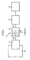
Fig. 1 is a schematic block diagram of an embodiment of an apparatus for carrying out volume measurement; -
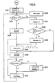
Fig. 2 is a flow diagram of a preferred embodiment of the inventive calibration; and -
Fig. 3 is a flow diagram of a preferred embodiment of the inventive volume measurement. -
Fig. 1 shows schematically how an automaticallycalibratable apparatus 1 for fuel volume determination can be composed and arranged. In this embodiment, the apparatus comprises a pulse generator 2, apulse correction unit 3, afuel pump computer 4 and a volume counter 5. - The
apparatus 1 is adapted to be arranged in a fuel pump unit. The pulse generator 2 is adapted to generate pulses corresponding to the volume flow rate when dispensing fuel from the fuel pump unit. To this end, the pulse generator 2 is arranged adjacent to the metering means 8 of the fuel pump unit, said metering means being arranged between a pump for pumping fuel from a fuel container and a nozzle for dispensing the fuel. Depending on the type of pulse generator, some part of the pulse generator 2 can besides be arranged in the metering means. - The pulse generator 2 emits pulses PA to the
pulse correction unit 3, which comprises aprocessor unit 6 with memory means 7 for storing correction factors and programs for carrying out the calibration and volume determination according to the invention. Thepulse correction unit 3 further comprises an input 9, through which an operator can enter a calibration signal. When thepulse correction unit 3 is correctly calibrated, it corrects the number of pulses in such a manner that when a predetermined volume of fuel flows through the metering means, thepulse correction unit 3 will always emit substantially a predetermined number of pulses independently of how many pulses the specific pulse generator emits for the predetermined volume. - In volume determination, the corrected number of pulses PC is supplied continuously to the
pump computer 4, where the pulses are processed in traditional manner and used for controlling the volume counter 5, which indicates the dispensed volume to the user. Thepump computer 4 can thus function in the same manner for all fuel pump units independently of the function of the specific pulse generator 2, since it will always receive substantially the same number of pulses per unit of volume. - With reference to the flow diagram in
Fig. 2 , a description follows below of how thepulse correction unit 3 can be calibrated for a specific pulse generator 2. In this embodiment it is assumed that the pulse generator generates more pulses per unit of volume than the predetermined, ideal number of pulses per unit of volume that is to be output from thepulse correction unit 3, and that the correction is carried out by skipping, at regular intervals, the output of a pulse from the pulse correction unit. Furthermore, it is assumed that the predetermined number of pulses per unit of volume has already been stored in the memory means 7, as well as a number of pulse intervals, each corresponding to a given calibration volume. - When the pulse correction unit is to be calibrated, the operator puts the
pulse correction unit 3 in calibration mode by giving a calibration signal on the input 9 of the unit. This can take place, for instance, by the operator pressing a calibration button. When the pulse correction unit detects that it is in calibration mode,step 201, it performs the steps described below in the subsequent dispensing of fuel. If it is not in calibration mode, the pulse correction unit processes the subsequent dispensing of fuel as normal dispensing for which the volume is to be determined,step 202. - When the operator has put the pulse correction unit in calibration mode, he dispenses a predetermined volume of fuel from the fuel pump unit. During dispensing, the pulse correction unit counts the number of pulses generated by the pulse generator during dispensing,
step 203. - When the volume of fuel selected by the operator has been dispensed, which is determined by the operator by means of a calibrated pitcher, the operator signals on the input 9 of the
pulse correction unit 3 that the dispensing operation is completed. When thepulse correction unit 3 detects this signal,step 204, it proceeds to step 205 and determines the volume that has been dispensed. This is carried out by comparing the counted number of pulses with the pulse intervals stored in the memory means 7. If the counted number of pulses is within one of these intervals, the pulse correction unit determines that the corresponding volume has been dispensed. If the counted number of pulses is not within one of the stored pulse intervals, it determines that no volume could be identified,step 206, and that the calibration therefore could not take place, whereupon the calibration is interrupted,step 207. - If a dispensed volume has been identified, the pulse correction unit determines, in
step 208, a first correction factor N as follows:
wherein INT is the integer part of the expression within parentheses, A is the number of pulses received from the pulse generator, k is the predetermined, ideal number of pulses for the identified, dispensed volume, and N indicates the number of pulses which the pulse correction unit should receive before refraining from outputting a pulse for effecting a correction. - Subsequently, the pulse correction unit determines,
step 209, a second correction factor M as follows:
wherein INT, A, k and N have the same meaning as above. M is used for correction of the decimal error that may arise when correcting by means of the correction factor N. The decimal error correction means that the pulse correction unit, for every Mth received pulse, refrains from carrying out the following correction carried out for every Nth pulse. - Finally, N and M are stored in the memory means 7 in the pulse correction unit, step 210, before completion of the calibration. Preferably, also the number of pulses A generated by the pulse generator 2 is stored in the memory means.
- Now supposing that the ideal number of pulses is 400 pulses per litre and that the pulse interval stored in the memory means 7 for 5 litres of fuel is 2000-2160 pulses. Assume further that, during calibration, the pulse correction unit receives 2077 pulses from the pulse generator when dispensing 5 litres of fuel from the fuel pump unit. The pulse correction unit then determines that 5 litres have been dispensed and that the ideal number of pulses is 2000. The pulse correction unit further calculates N as follows: N = INT (2077 / (2077-2000)) = 26. Thus, this means that in the volume determination, every 26th pulse is to be skipped in order to output substantially the ideal number of pulses from the pulse correction unit.
- By using the correction factor N, exactly the ideal number of pulses will not be obtained in all cases. The number of pulses obtained when dispensing 5 litres of fuel can be determined as follows: p = INT(A*(N-1)/(N)), which in this example becomes 1997, which yields an error of 0.15%.
- In order to further reduce the error, the second correction factor M is used, which in this case becomes 666. When the pulse correction unit has received 666 pulses, the subsequent correction by skipping should thus not be carried out. In this example, the use of M means that the pulse correction unit will output 2000 pulses for 5 litres.
- The calibration can, of course, be carried out for a number of different volumes. Moreover, the calibration can be effected for different flow rates, in which case the flow rate when dispensing can be determined by counting the number of pulses generated per unit of time.
- A presently preferred embodiment of the volume determination according to the invention will be described below with reference to the flow diagram in
Fig. 3 . - To keep a check when a pulse is to be skipped or not, the pulse correction unit uses two variables Ncounter and Mcounter. Moreover, use is made of a variable which is designated loop counter. These variables are set at zero,
step 301, after each calibration. - When the pulse correction unit detects a pulse from the pulse generator,
step 302, it investigates whether the value of the Ncounter equals N-1,step 303. If this is not the case, the Ncounter is incremented by 1,step 304, and the Mcounter by 1, step 305. Then the pulse correction unit proceeds to step 306. If, on the other hand, the value of the Ncounter equals N-1, it is set at zero,step 307. Subsequently, the pulse correction unit investigates whether M differentiates from zero and if the value of the Mcounter is greater than or equal to M-1, step 308. If this is the case, the Mcounter is set at zero,step 309, and the pulse correction unit proceeds to step 306, in which the pulse correction unit outputs a pulse to the pump computer and then proceeds to step 310, in which the loop counter is incremented by 1. If the condition in step 308 is not satisfied, the pulse correction unit proceeds to step 310, in which the loop counter is incremented. After step 310, the pulse correction unit checks instep 311 if the value of the loop counter is greater than or equal to A, which is the number of pulses generated by the pulse generator 2 during calibration when N and M were determined. If this is the case, the loop counter, the Ncounter and the Mcounter are cleared in step 312. Finally, thepulse correction unit 3 returns to step 302. By operating in measuring periods corresponding to A generated pulses and clearing all counters between the measuring periods, the errors are minimised. - If the volume determination is to be carried out with regard to the flow rate when dispensing fuel, various N and M can be determined for various flow rates. In the volume determination, N and M are then selected corresponding to the flow rate. Alternatively, one or more further compensation factors can be used to accomplish flow compensation.
- The above Examples relate to a case where the number of generated pulses is greater than the desired number of pulses such that pulses must be skipped for correcting the number of pulses. The Examples are also applicable to the case where the number of generated pulses is smaller than the desired number of pulses. The only modification that is needed in this case is to exchange the skipping for an addition of a pulse.
Claims (12)
- A method for determining the volume of fuel being dispensed from a fuel pump unit, comprising the steps of generating pulses by means of a pulse generator corresponding to a volume flow rate when dispensing fuel, and correcting the number of pulses generated by the pulse generator by at least one correction factor, thereby emitting substantially a predetermined number of pulses per unit of volume of fuel that is being dispensed, characterised in that the step of correction comprises counting the pulses generated by the pulse generator and, for at least one first period of a volume determination, carrying out one of the measures of skipping every Nth counted pulse and emitting a pulse in addition to the pulses generated by the pulse generator for every Nth counted pulse, N constituting said correction factor and being an integer which is greater than one and which during a calibration has been predetermined for said pulse generator, said skipping of every Nth pulse taking place if the number of generated pulses is greater than the predetermined number of pulses, and said additional emitting of a pulse taking place if the number of generated pulses is smaller than the predetermined number of pulses.
- The method as claimed in claim 1, wherein none of the measures is carried out for at least one second period of the volume determination.
- The method as claimed in claim 1 or 2, wherein the step of correction further comprises refraining once, for every Mth counted pulse, from carrying out said one of the measures, M being an integer which is greater than N and being predetermined for said pulse generator.
- The method as claimed in anyone of the preceding claims, wherein the step of correction further comprises the steps of determining the volume flow rate when dispensing fuel, and selecting said at least one correction factor corresponding to the volume flow rate.
- The method as claimed in anyone of the preceding claims, wherein the predetermined number of pulses per unit of volume is determined to be greater than 100 pulses per litre of fuel.
- A method for calibrating an apparatus for determining the volume of fuel being dispensed from a fuel pump unit, said apparatus comprising a pulse generator (2), which is adapted to generate pulses corresponding to the volume flow rate when dispensing fuel, and means (3) for correcting the number of pulses generated by the pulse generator by at least one correction factor, such that the correction means emit substantially a predetermined number of pulses per unit of volume of dispensed fuel, said method comprising the steps of
making the fuel pump unit dispense a predetermined calibration volume;
counting the number of pulses generated by the pulse generator when dispensing the calibration volume;
determining the size of the correction factor by means of said predetermined number of pulses, the size of the predetermined calibration volume and the counted number of pulses; and
storing the correction factor in the apparatus to be used in the determination of fuel volume, characterised in that the correction factor during the calibration is determined to be an integer N, which is greater than 1 and such that if the apparatus when emitting the pulses carries out one of the measures of skipping every Nth pulse and adding a pulse for every Nth counted pulse, the apparatus will emit substantially the predetermined number of pulses per unit of volume, said skipping of every Nth pulse taking place if the number of generated pulses is greater than the predetermined number of pulses, and said additional emitting of a pulse taking place if the number of generated pulses is smaller than the predetermined number of pulses. - The method as claimed in claim 6, further comprising the steps of determining a further correction factor, which is an integer M, which is greater than N and which is such that if the apparatus, for every 14th counted pulse, refrains once from carrying out said one of the measures, a pulse number is obtained which is closer to the desired pulse number than that obtained if said one of the measures is carried out every time; and storing the integer M in the apparatus to be used in the determination of fuel volume.
- The method as claimed in claim 6 or 7, wherein the predetermined number of pulses per unit of volume is stored in the apparatus, and wherein the steps of counting the number of pulses, determining the correction factor and storing the correction factor are carried out automatically by the apparatus.
- The method as claimed in anyone of claims 6-8, further comprising the steps of storing a plurality of pulse numbers, each corresponding to a predetermined calibration volume, in the apparatus, and making the apparatus determine the size of the calibration volume by comparing the counted number of pulses with said plurality of predetermined pulse numbers.
- An apparatus for determining the volume of fuel dispensed from a fuel pump unit, comprising a pulse generator (2) which is adapted to generate pulses corresponding to the volume flow rate, means (3) for correcting the number of pulses generated by the pulse generator by at least one correction factor, such that the apparatus emits substantially a predetermined number of pulses per unit of volume of fuel that is being dispensed,
characterised in that the correction means (3) are adapted to carry out the correction in accordance with anyone of claims 1-5. - The apparatus as claimed in claim 10, wherein the apparatus further is calibratable in accordance with anyone of claims 6-9.
- The apparatus as claimed in claim 10 or 11, wherein the correction means (3) comprise a processor unit (6) and its associated software.
Applications Claiming Priority (3)
| Application Number | Priority Date | Filing Date | Title |
|---|---|---|---|
| SE9604075A SE511133C2 (en) | 1996-11-07 | 1996-11-07 | Method and device for volume determination |
| SE9604075 | 1996-11-07 | ||
| PCT/SE1997/001865 WO1998020308A1 (en) | 1996-11-07 | 1997-11-07 | Method and apparatus for volume determination |
Publications (2)
| Publication Number | Publication Date |
|---|---|
| EP0938650A1 EP0938650A1 (en) | 1999-09-01 |
| EP0938650B1 true EP0938650B1 (en) | 2012-12-19 |
Family
ID=20404527
Family Applications (1)
| Application Number | Title | Priority Date | Filing Date |
|---|---|---|---|
| EP97912624A Expired - Lifetime EP0938650B1 (en) | 1996-11-07 | 1997-11-07 | Method and apparatus for volume determination |
Country Status (5)
| Country | Link |
|---|---|
| US (1) | US5929314A (en) |
| EP (1) | EP0938650B1 (en) |
| AU (1) | AU4974997A (en) |
| SE (1) | SE511133C2 (en) |
| WO (1) | WO1998020308A1 (en) |
Families Citing this family (10)
| Publication number | Priority date | Publication date | Assignee | Title |
|---|---|---|---|---|
| US6250130B1 (en) * | 1995-07-10 | 2001-06-26 | Bayer Corporation | Method and apparatus for monitoring an aspirating and dispensing system |
| DE19635435A1 (en) * | 1996-09-02 | 1998-03-05 | Salzkotten Tankanlagen | Liquid measuring device and method |
| US6412328B1 (en) * | 1996-10-25 | 2002-07-02 | Speedline Technologies, Inc. | Method and apparatus for measuring the size of drops of a viscous material dispensed from a dispensing system |
| US6092410A (en) * | 1998-02-20 | 2000-07-25 | Marconi Commerce Systems Inc. | Meter calibration and drift compensation device |
| US6745104B1 (en) | 2000-01-31 | 2004-06-01 | Gilbarco Inc. | Fraud detection through general inference |
| US7076330B1 (en) * | 2000-01-31 | 2006-07-11 | Gilbarco Inc. | Fraud detection through flow rate analysis |
| KR100483985B1 (en) * | 2001-11-27 | 2005-04-15 | 삼성에스디아이 주식회사 | Polysilicon thin layer for thin film transistor and device using thereof |
| US8108128B2 (en) * | 2009-03-31 | 2012-01-31 | Dresser, Inc. | Controlling exhaust gas recirculation |
| US8444014B2 (en) * | 2009-10-16 | 2013-05-21 | Gilbarco Inc. | System and method for fraud detection by low flow rate monitoring at a fuel dispenser |
| PL2835242T3 (en) * | 2010-02-12 | 2021-05-04 | Mac Investments B.V. | Method, device and a computer program for manufacturing a pre-insulated skeleton framing segment |
Family Cites Families (4)
| Publication number | Priority date | Publication date | Assignee | Title |
|---|---|---|---|---|
| DE2926451A1 (en) * | 1979-06-30 | 1981-01-15 | Scheidt & Bachmann Gmbh | VOLUME METER WITH MOVABLE PARTITIONS |
| JPS58223021A (en) * | 1982-06-21 | 1983-12-24 | Oval Eng Co Ltd | Circuit for adjusting instrumental error |
| CA1293568C (en) * | 1987-10-01 | 1991-12-24 | Romet Limited | Electronic volume correctors |
| US4831866A (en) * | 1987-11-09 | 1989-05-23 | Tokheim Corporation | Automatic meter proving and calibration system |
-
1996
- 1996-11-07 SE SE9604075A patent/SE511133C2/en unknown
-
1997
- 1997-11-06 US US08/964,381 patent/US5929314A/en not_active Expired - Lifetime
- 1997-11-07 EP EP97912624A patent/EP0938650B1/en not_active Expired - Lifetime
- 1997-11-07 WO PCT/SE1997/001865 patent/WO1998020308A1/en not_active Ceased
- 1997-11-07 AU AU49749/97A patent/AU4974997A/en not_active Abandoned
Also Published As
| Publication number | Publication date |
|---|---|
| WO1998020308A1 (en) | 1998-05-14 |
| SE9604075L (en) | 1998-05-08 |
| AU4974997A (en) | 1998-05-29 |
| US5929314A (en) | 1999-07-27 |
| SE511133C2 (en) | 1999-08-09 |
| SE9604075D0 (en) | 1996-11-07 |
| EP0938650A1 (en) | 1999-09-01 |
Similar Documents
| Publication | Publication Date | Title |
|---|---|---|
| US5016187A (en) | Linearized turbine flow meter for fuel dispensers | |
| US5929314A (en) | Method and apparatus for volume determination | |
| US4487333A (en) | Fluid dispensing system | |
| US4831866A (en) | Automatic meter proving and calibration system | |
| RU2202104C2 (en) | Method of overfilling compensation for metering equipment | |
| EP0100844B1 (en) | Instrumental error compensation circuit for flow meter | |
| CA2025450A1 (en) | Variable blending dispenser | |
| RU99128025A (en) | METHOD FOR COMPENSATION OF OVERFILL FOR DOSING EQUIPMENT | |
| CN1165753C (en) | liquid measuring device and method | |
| US20050283329A1 (en) | Nullification of measurement error, particularly within a dual turbine flow meter used in a fuel dispenser | |
| EP0288448A1 (en) | Method and apparatus for measuring the volum of a flowing liquid | |
| US11454526B2 (en) | Fluid flow meter with linerarization | |
| EP1019683B1 (en) | Method and apparatus for calibration | |
| JPH0312275B2 (en) | ||
| US5225995A (en) | Flow rate measurement control for refuelling control system | |
| EP0562976A1 (en) | Luminance measurement method and apparatus | |
| US6268736B1 (en) | Densitometer using microwaves | |
| US20190341073A1 (en) | Display device | |
| US6702152B1 (en) | Dosing control for helical dosing equipment | |
| US5847285A (en) | Volume compensating pressure regulated flow control dispensing system | |
| CN115700100B (en) | Parameter calibration method and device of batching machine, storage medium, and batching equipment | |
| JPS6175217A (en) | Instrument error correction device for flowmeter | |
| EP0764896B1 (en) | Volume compensating pressure regulated flow control dispensing system | |
| JPH04339289A (en) | Laser distance measurement device | |
| US4941160A (en) | Frequency multiplier circuitry and method |
Legal Events
| Date | Code | Title | Description |
|---|---|---|---|
| PUAI | Public reference made under article 153(3) epc to a published international application that has entered the european phase |
Free format text: ORIGINAL CODE: 0009012 |
|
| 17P | Request for examination filed |
Effective date: 19990507 |
|
| AK | Designated contracting states |
Kind code of ref document: A1 Designated state(s): DE FR GB IT SE |
|
| RIN1 | Information on inventor provided before grant (corrected) |
Inventor name: BJURNEMARK, ANDERS Inventor name: BERGKVIST, ANDERS |
|
| RAP1 | Party data changed (applicant data changed or rights of an application transferred) |
Owner name: DRESSER WAYNE AB |
|
| GRAP | Despatch of communication of intention to grant a patent |
Free format text: ORIGINAL CODE: EPIDOSNIGR1 |
|
| RIC1 | Information provided on ipc code assigned before grant |
Ipc: G01F 25/00 20060101AFI20120531BHEP Ipc: G01F 3/00 20060101ALI20120531BHEP |
|
| GRAS | Grant fee paid |
Free format text: ORIGINAL CODE: EPIDOSNIGR3 |
|
| GRAA | (expected) grant |
Free format text: ORIGINAL CODE: 0009210 |
|
| AK | Designated contracting states |
Kind code of ref document: B1 Designated state(s): DE FR GB IT SE |
|
| REG | Reference to a national code |
Ref country code: GB Ref legal event code: FG4D |
|
| REG | Reference to a national code |
Ref country code: DE Ref legal event code: R096 Ref document number: 69740528 Country of ref document: DE Effective date: 20130214 |
|
| REG | Reference to a national code |
Ref country code: SE Ref legal event code: TRGR |
|
| PLBE | No opposition filed within time limit |
Free format text: ORIGINAL CODE: 0009261 |
|
| STAA | Information on the status of an ep patent application or granted ep patent |
Free format text: STATUS: NO OPPOSITION FILED WITHIN TIME LIMIT |
|
| 26N | No opposition filed |
Effective date: 20130920 |
|
| REG | Reference to a national code |
Ref country code: DE Ref legal event code: R097 Ref document number: 69740528 Country of ref document: DE Effective date: 20130920 |
|
| PGFP | Annual fee paid to national office [announced via postgrant information from national office to epo] |
Ref country code: GB Payment date: 20141107 Year of fee payment: 18 Ref country code: SE Payment date: 20141117 Year of fee payment: 18 Ref country code: DE Payment date: 20141105 Year of fee payment: 18 |
|
| PGFP | Annual fee paid to national office [announced via postgrant information from national office to epo] |
Ref country code: FR Payment date: 20141120 Year of fee payment: 18 |
|
| PGFP | Annual fee paid to national office [announced via postgrant information from national office to epo] |
Ref country code: IT Payment date: 20141113 Year of fee payment: 18 |
|
| REG | Reference to a national code |
Ref country code: DE Ref legal event code: R119 Ref document number: 69740528 Country of ref document: DE |
|
| GBPC | Gb: european patent ceased through non-payment of renewal fee |
Effective date: 20151107 |
|
| PG25 | Lapsed in a contracting state [announced via postgrant information from national office to epo] |
Ref country code: IT Free format text: LAPSE BECAUSE OF NON-PAYMENT OF DUE FEES Effective date: 20151107 |
|
| REG | Reference to a national code |
Ref country code: FR Ref legal event code: ST Effective date: 20160729 |
|
| PG25 | Lapsed in a contracting state [announced via postgrant information from national office to epo] |
Ref country code: SE Free format text: LAPSE BECAUSE OF NON-PAYMENT OF DUE FEES Effective date: 20151108 |
|
| PG25 | Lapsed in a contracting state [announced via postgrant information from national office to epo] |
Ref country code: GB Free format text: LAPSE BECAUSE OF NON-PAYMENT OF DUE FEES Effective date: 20151107 Ref country code: DE Free format text: LAPSE BECAUSE OF NON-PAYMENT OF DUE FEES Effective date: 20160601 |
|
| PG25 | Lapsed in a contracting state [announced via postgrant information from national office to epo] |
Ref country code: FR Free format text: LAPSE BECAUSE OF NON-PAYMENT OF DUE FEES Effective date: 20151130 |