EP0937814A2 - A decoupling controller for use with a process having two input variables and two output variables - Google Patents
A decoupling controller for use with a process having two input variables and two output variables Download PDFInfo
- Publication number
- EP0937814A2 EP0937814A2 EP99103195A EP99103195A EP0937814A2 EP 0937814 A2 EP0937814 A2 EP 0937814A2 EP 99103195 A EP99103195 A EP 99103195A EP 99103195 A EP99103195 A EP 99103195A EP 0937814 A2 EP0937814 A2 EP 0937814A2
- Authority
- EP
- European Patent Office
- Prior art keywords
- outputs
- pair
- decoupling controller
- junctions
- units
- Prior art date
- Legal status (The legal status is an assumption and is not a legal conclusion. Google has not performed a legal analysis and makes no representation as to the accuracy of the status listed.)
- Withdrawn
Links
- 238000000034 method Methods 0.000 title claims abstract description 61
- 230000008569 process Effects 0.000 title claims abstract description 56
- 238000006880 cross-coupling reaction Methods 0.000 claims abstract description 12
- 238000012546 transfer Methods 0.000 claims abstract description 11
- 238000005259 measurement Methods 0.000 claims description 16
- 230000008859 change Effects 0.000 claims description 9
- 239000000835 fiber Substances 0.000 claims description 6
- 230000001133 acceleration Effects 0.000 claims description 3
- 230000003247 decreasing effect Effects 0.000 claims description 2
- 238000012360 testing method Methods 0.000 claims description 2
- 230000008878 coupling Effects 0.000 claims 2
- 238000010168 coupling process Methods 0.000 claims 2
- 238000005859 coupling reaction Methods 0.000 claims 2
- 238000001914 filtration Methods 0.000 claims 2
- 238000012935 Averaging Methods 0.000 claims 1
- 238000004132 cross linking Methods 0.000 abstract 1
- 238000010586 diagram Methods 0.000 description 3
- 230000004044 response Effects 0.000 description 3
- 230000007704 transition Effects 0.000 description 3
- XLYOFNOQVPJJNP-UHFFFAOYSA-N water Substances O XLYOFNOQVPJJNP-UHFFFAOYSA-N 0.000 description 3
- 230000001143 conditioned effect Effects 0.000 description 2
- 239000007788 liquid Substances 0.000 description 2
- 238000012545 processing Methods 0.000 description 2
- 239000000126 substance Substances 0.000 description 2
- 239000000654 additive Substances 0.000 description 1
- 230000000996 additive effect Effects 0.000 description 1
- 230000001808 coupling effect Effects 0.000 description 1
- 230000001419 dependent effect Effects 0.000 description 1
- 230000000694 effects Effects 0.000 description 1
- 230000010354 integration Effects 0.000 description 1
- 238000005065 mining Methods 0.000 description 1
- 239000000203 mixture Substances 0.000 description 1
- 230000001360 synchronised effect Effects 0.000 description 1
- 230000001052 transient effect Effects 0.000 description 1
- 238000004065 wastewater treatment Methods 0.000 description 1
Images


Classifications
-
- D—TEXTILES; PAPER
- D21—PAPER-MAKING; PRODUCTION OF CELLULOSE
- D21G—CALENDERS; ACCESSORIES FOR PAPER-MAKING MACHINES
- D21G9/00—Other accessories for paper-making machines
- D21G9/0009—Paper-making control systems
- D21G9/0027—Paper-making control systems controlling the forming section
-
- D—TEXTILES; PAPER
- D21—PAPER-MAKING; PRODUCTION OF CELLULOSE
- D21G—CALENDERS; ACCESSORIES FOR PAPER-MAKING MACHINES
- D21G9/00—Other accessories for paper-making machines
- D21G9/0009—Paper-making control systems
- D21G9/0036—Paper-making control systems controlling the press or drying section
-
- G—PHYSICS
- G01—MEASURING; TESTING
- G01N—INVESTIGATING OR ANALYSING MATERIALS BY DETERMINING THEIR CHEMICAL OR PHYSICAL PROPERTIES
- G01N33/00—Investigating or analysing materials by specific methods not covered by groups G01N1/00 - G01N31/00
- G01N33/34—Paper
-
- Y—GENERAL TAGGING OF NEW TECHNOLOGICAL DEVELOPMENTS; GENERAL TAGGING OF CROSS-SECTIONAL TECHNOLOGIES SPANNING OVER SEVERAL SECTIONS OF THE IPC; TECHNICAL SUBJECTS COVERED BY FORMER USPC CROSS-REFERENCE ART COLLECTIONS [XRACs] AND DIGESTS
- Y10—TECHNICAL SUBJECTS COVERED BY FORMER USPC
- Y10S—TECHNICAL SUBJECTS COVERED BY FORMER USPC CROSS-REFERENCE ART COLLECTIONS [XRACs] AND DIGESTS
- Y10S162/00—Paper making and fiber liberation
- Y10S162/09—Uses for paper making sludge
- Y10S162/10—Computer control of paper making variables
Definitions
- the present invention is directed to a decoupling controller for use with a process having two input variables and two output variables and, more specifically, to a paper-making process where the input variables are dry stock flow and steam pressure to a dryer section and the output variables are basis weight and moisture.
- the process itself has long deadtimes relative to the process time constant. This makes control difficult. There are typically two unique deadtimes; one is for the time required for a change in basis weight when the input variable, stock flow, is changed and the other is the time for variation in steam to affect the final moisture carried by the paper sheet.
- a further difficulty in the paper-making process is the cross-coupling affect; that is, each input variable affects both output variables.
- a decoupling controller is desired to regulate the outputs independently; for example, the operator would like to change the setpoint of the basis weight controller without changing the value of the moisture.
- a setpoint is changed only once every five minutes, for example, for changes in stock flow and once every minute for changes in steam. This is a much longer period of time than the generation of output data by a sensor which scans across the width of the paper, for example, every 20 seconds.
- a second proposed decoupling technique is to provide absolute decoupling constants between changes in stock flow and steam pressure. These might be termed "compensating changes". However, these are mere guesses and do not compensate for grade changes or speed changes and do not take into account that the coupling effect may be nonlinear.
- One other problem with a controller for a paper-making machine discussed above, is the fact that the measurements of outputs occur either at long intervals or can occur asynchronously due to sheet breaks or standardization. In any case, scan measurements (which may take up to 120 seconds) only occur every 20 seconds at best.
- a general object of the present invention is to provide an improved decoupling controller for use with a process having two input variables and two output variables.
- a decoupling controller for use with a process having two input variables U1, U2 and two output variables X1, X2 where in the process each input variable affects both output variables (that is they are coupled), such process having desired setpoints S1, S2 for the output variables.
- Such decoupling controller comprising two pairs of linked internal model controllers, each internal model controller (IMC) including a proportional, integral, derivative (P.I.D.) velocity unit C11, C21, C12, and C22 for respectively receiving from a first pair of difference junctions total process error, et1, et2, in a feedback loop for the process and producing said input variables U1, U2, which are control inputs to the process itself, such P.I.D. units taking into account loop, proportional, integral and derivative gains of the feedback loop for both direct and cross-coupling.
- P.I.D. proportional, integral, derivative
- first order transfer function units K11, K12, K21, and K22 receive as inputs U1, U2, the K11, K22 units providing predicted values of X1, X2, the K21, K12 units providing predicted outputs of X1, X2 due to cross-coupling.
- Means feed back to a pair of second summing junctions the outputs of K11, K12 and K22, K21 respectively.
- Means couple the outputs of the second summing junctions, which are total predicted values of X1 and X2 taking into account cross-coupling, to a pair of third summing junctions, which also receive modeling error signals representing the difference between the actual X1 and X2 values and estimated values Y1 and Y2, from a pair of fifth junctions.
- Means feed the summed output of the third pair of summing junctions to the first pair of difference junctions, which have as the other difference input the setpoints S1, S2 to provide the total process error inputs et1 and et2 to C11, C21 and C12, C22;
- Means take the deadtime of the process into account (that is the lag time between the change of input variables and output variables), including four deadtime units, D11, D21, and D12, D22, having their inputs respectively connected to the outputs of K11, K21, K12, and K22, including a pair of fourth summing junctions having as outputs the current estimated values Y1, Y2 of the X1, X2 output variables, where one of the pair of fourth summing junctions, sums the outputs of D11, D12 and the other of the pair of summing junctions, sums the outputs of D22, D21.
- Means couple the outputs of the fourth pair of summing junctions, to the fifth pair of difference junctions to take the difference between the actual outputs X1, X2 and the estimated values Y1, Y2, such differences being the modeling error signals.
- Means feed back the modeling error signals to the third pair of summing junctions.
- FIG. 1 illustrates a typical paper-making machine, which includes an associated control hardware and software configuration as used in the present invention.
- Raw paper stock is supplied to the machine via a stock valve 10 and a stock line 11 to a head box 12 by a fan pump 13.
- the paper sheet passes through a dryer section 19 consisting of several rollers to which steam is supplied by steam control valve 20.
- the paper passes through a calendar stack 22 through scanning sensors 23 and is wound on the reel 24.
- Scanning sensors 23 scan across the width of the paper approximately every 20 seconds and provide a measurement of the output variables of basis weight (B.W.) and moisture (MOI). In the present invention, either basis weight, dry weight, or conditioned weight may be used; the latter is preferred. Conditioned weight is from a practical standpoint, dry weight where a standard 8 percent moisture factor is added.
- the two output variables from the scanning sensors 23 are also designated X1 and X2.
- the scanned moisture and basis weight values are coupled to the digital computer 26 for processing along with an operator input 25. Typically, in the cross direction of the paper, 240 measurements are made and these are averaged to provide a single "end of scan" measurement. This is therefore one of the measurements made in the machine direction.
- Both basis weight and moisture are also connected to control units 30A and 30B in a manner which will be illustrated in Figure 2.
- the two control units are actually part of a single interlinked decoupling controller embodying the present invention as indicated by the 6-wire interface 31.
- Controller portion 30A has as inputs a setpoint S1 from the digital computer 26 and X1 and as an output, the control value U1, which drives the stock valve 10 to provide a dry stock (fiber) flow rate of U1.
- controller portion 30B receives the setpoint S2 (actually, the steam pressure) from digital computer 26 along with X2 and by its output U2 drives the steam valve 20 to provide a U2 steam input.
- Digital computer 26 has as other feedbacks the steam pressure line 31 from dryer section 19 and also flow meter 27 and a consistency meter 32, which determine the pounds per minute of dry stock flow.
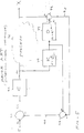
- the decoupling controller portions 30A and 30B are shown in greater detail and especially how they are interlinked.
- the paper-making process, fully illustrated in Figure 1 is shown twice, both at 32A and 32B, as being driven by the input variables U1 (stock flow) and U2 (steam) and having the outputs X1 (basis weight) and X2 (moisture).
- the real process illustrated in Fig. 3, is represented by four unknown transfer functions P 11 , P 12 , P 21 , and P 22 .
- the P-type functions represent the direct transfer functions of stock to basis weight and steam to moisture; the other cross-coupling subscripts 21 and 12, relate to how moisture is affected by changing stock and how basis weight is affected by a change in steam.
- the P functions can be represented by the associated Laplace Transform where the theta superscript is a deadtime function or delay function and the remainder is a time constant and gain, or rather a first order transfer function K.
- Figure 4 illustrates the delay or deadtime of the process. Assuming a time, t o , when a change is made for stock, there is a delay until basis weight reaches a constant value; and the same is true for the change in steam for moisture. In the background of the invention, prior attempts at decoupling were discussed.
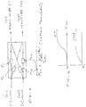
- FIG. 5 With regard to the present invention and referring to Figure 5, it has been found that when a prior art type internal model controller (IMC), as shown in Figure 5, for a single loop only and for synchronous measurements in time, is adapted to a multi-variable system, it will accommodate deadtime, asynchronous behavior, and when two pairs of IMC's are linked, as is illustrated in Figure 2, provide very effective decoupling.
- the internal model controller has a setpoint input S and a process at 36 and an output variable X.
- a difference junction 37 provides a total error signal, et, to a controller C, 40, which then provides an input control signal U to the process 36.
- This input control signal also drives a simulated model of process 36, which is characterized by the Laplace Transform (see Figure 3) of a K function 38 and a D function 39 as illustrated by the accompanying formulas.
- This process model provides an estimated X value at 41, which at the difference junction 42 is compared to the actual X value to generate a feedback error signal on line 43.
- this error signal is not coupled back to the input until it is summed at a junction 44 with the raw output of the K model 38 (that is before a deadtime is taken into account). Then on line 46 and junction 37, a difference is taken with the setpoint, S, to provide the total error, et.
- the unit 40 is actually a proportional, integral, derivative (P.I.D.) type controller which is illustrated by the following equation which produces an output U in response to a total error input, et:
- the internal model controller models the process 36 by the use of the first order transfer function K (unit 38) with a deadtime D (unit 39).
- this internal model controller (IMC) is for a single loop only and not for asynchronous use.
- IMC internal model controller
- D deadtime
- P.I.D. proportional integral derivative
- the C-type unit 40 of Figure 5 designated 40', has two pairs of linked P.I.D. units C11, C21, C12, and C22.
- the numerical designations conform to the transfer functions illustrated in Figure 3.
- C11 and C22 are the direct model of the process change for driving U1 and U2, respectively, and then for the other two, C21 relates to S1, X2, and C12 to S2, X1.
- these P.I.D. units are cross-coupled to produce at the additive junctions 51 and 52, the U1 and U2 control values to the process 36A, 36B.
- the units 40' are of the P.I.D. velocity type to eliminate "reset windup".
- the units 40' take into account loop gain, proportional gain, integral gain, and derivative gains involved in the feedback loops illustrated in Figure 2.
- the K11, K21, and K12, K22 units receive as respective inputs U1, U2.
- the K12 and K21 units provide predicted outputs of X1, X2 due to cross-coupling. These outputs, in manner somewhat similar to Figure 5, are cross-coupled back to junctions 2a and 2b and summed with the K11 and K22 outputs.
- the output of the second summing injunction pair, 2a and 2b is actually the total predicted value of X1 and X2 (taking into account cross-coupling, but without deadtime). These are designated yp1 and yp2.
- junctions 3a and 3b which also receive on the lines 53 and 54 modeling error signals representing the difference between the actual X1 and X2 values and the estimated values, Y1 and Y2.
- outputs of the junctions 3a and 3d are fed back to the first pair of difference junctions 1a and 1b to provide the total process error, et1 and et2.
- Deadtime is taken in account by the D units 39' which receive the outputs of the respective K units.
- the deadtime is, of course, the lag time between the change of input variables and output variables.
- the deadtime units D11, D21 and D12, D22 have their inputs respectively connected to the outputs of K11, K21 and K12, K22.
- a current estimate Y1, Y2 of the X1 and X2 output variables is provided at the summing junctions 4a and 4b; junction 4a sums D11 and the cross-coupled D12 and junction 4b sums D22 and the cross-coupled D21.
- junctions 5a, 5b take the difference between the actual outputs X1 and X2 and the estimated values Y1 and Y2 to provide the modeling error signal on lines 53 and 54.
- the internal model controller of Figure 5 has been converted by the specific interlinking as shown in Figure 2 to compensate for deadtime and provide for instant response to setpoint changes and at the same time to effectively decouple weight from moisture.
- the above process model with four transfer functions also accommodates use in a wide variety of processes in addition to paper machines, such as in the petrochemical, mining, waste water treatment and food processing industries.
- the gas or liquid stream is sampled isokinetically with the sample drawn to a chemical analyzer, such as a gas or liquid chromatograph resulting in a time lag.
- the P.I.D. units 40' are preferably implemented in the velocity mode to eliminate "reset wind-up". However, depending on the process other type modes might be used.
- Figure 6 illustrates typical data received in the machine direction of either basis weight or moisture. Five data points are illustrated.
- the use of a sliding least squares method of polynomial filters provides a single best estimated value of X1 or X2, as well as dx/dt and dx 2 /dt 2 which, of course, relate to velocity and acceleration.
- the loop gain, K L (see Figure 5) of the controller units 40' is set as the inverse of the related K functions of the K11, K12, K21, and K22 modeling units.
- K11 first order transfer function is adjusted for an increase in the paper machines' speed (or trim).
- K L loop gain
- the loop gain, K L of the P.I.D. is decreased since it is the inverse of K11.
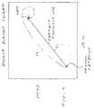
- Figure 7 shows a method of displaying the two dependent variables such as basis weight and moisture.
- the display includes the last 20 values of weight and moisture displayed on an XY chart with connecting lines between the data points.
- the chart is known as a phase planes chart in control theory and is used to analyze regions of stability and performance under transient conditions.
- the straight line 61 this is a perfect transition between an original setpoint and a new setpoint.
- the dashed line 62 illustrates a somewhat imperfect transition which, however, presents to the operator a possibility of improving by tuning the feedback system, the transition.
Landscapes
- Feedback Control In General (AREA)
- Paper (AREA)
- Control Of Non-Electrical Variables (AREA)
Abstract
Description
- KL =
- loop gain
- KP =
- proportional gain (generally approx. less 1)
- KI/s =
- integral gain (this is an acceleration factor which is about 0.5) and s is the Laplace operator.
- Kds =
- Kd is derivative gain which is in the range of 0.3 to 0.8 and s is the Laplace operator.
- D1n -
- input fiber rate, g/sec,
- DW -
- output dry weight scan average, g/m2,
- K11 -
- process gain,
- S -
- speed of paper, m/min,
- t -
- trim of paper, m
Claims (14)
- A decoupling controller for use with a process having two input variables U1, U2 and two output variables X1, X2 where in the process each input variable affects both output variables (that is they are coupled), such process having desired setpoints S1, S2 for said output variables such decoupling controller comprising:two pairs of linked internal model controllers, each internal model controller (IMC) including a proportional, integral, derivative (P.I.D.) velocity unit C11, C21, C12, and C22 for respectively receiving from a first pair of difference junctions total process error, et1, et2, in a feedback loop for the process and producing inputs U1, U2, which are control inputs to the process itself, such P.I.D. units taking into account loop, proportional, integral, and derivative gains of the feedback loop for both direct and cross-coupling;four first order transfer function units K11, K12, K21, and K22 for receiving as inputs U1, U2, said K11, K22 units providing predicted values of X1, X2, said K21, K12 units providing predicted outputs of X1, X2 due to cross-coupling;means for feeding back to a pair of second summing junctions the outputs of K11, K12 and K22, K21 respectively;means for coupling the outputs of said second summing junctions, which are total predicted values of X1 and X2 taking into account cross-coupling, to a pair of third summing junctions, which also receive modeling error signals representing the difference between the actual X1 and X2 values and estimated values Y1 and Y2, from a pair of fifth junctions;means for feeding the summed output of said third pair of summing junctions to said first pair of difference junctions, which have as the other difference input the setpoints S1, S2 to provide said total process error inputs et1 and et2 to C11, C21 and C12, C22;means for taking the deadtime of said process into account (that is the lag time between the change of input variables and output variables), including four deadtime units, D11, D21, and D12, D22, having their inputs respectively connected to the outputs of K11, K21, K12, and K22, including a pair of fourth summing junctions having as outputs said current estimated values Y1, Y2 of the X1, X2 output variables, where one of the pair of fourth summing junctions, sums the outputs of D11, D12 and the other of the pair of summing junctions, sums the outputs of D22, D21;means for coupling the outputs of said fourth pair of summing junctions, to a fifth pair of difference junctions to take the difference between the actual outputs X1, X2 and the estimated values Y1, Y2, such differences being said modeling error signals;and means for feeding back said modeling error signals to said third pair of summing junctions.
- A decoupling controller as in claim 1 where said C11 unit relates to S1, X1; C21 to S1, X2; C22 to S2, X2; and C12 to S2, X1; and where the summed outputs of C11 and C12 provide U1 and the summed outputs of C22 and C21 provide U2.
- A decoupling controller as in claim 1 where said process is a paper making machine having as input variables dry stock flow (U1) and steam pressure (U2) and as output variables basis weight (X1) and moisture (X2).
- A decoupling controller as in claim 3 where measurement of said output variables occur asynchronously or between long intervals.
- A decoupling controller as in claim 4 where a plurality of said measurements are made over said paper in a machine direction and including polynomial filtering means for such measurements to produce a best estimate of value.
- A decoupling controller as in claim 5 where said paper is scanned in a cross-direction to provide a plurality of measurements of X1, X2 including means for averaging to provide an end of scan measurement which constitutes one of said plurality of measurements in such machine direction.
- A decoupling controller as in claim 6 where said polynomial filtering also provides first and second derivatives related to velocity and acceleration.
- A decoupling controller as in claim 1 where said loop gain of said internal model controllers is the inverse of a related K12, K12, K21, and K22 unit.
- A decoupling controller as in claim 3 where said K11, the process gain for stock, is increased for an increase in the paper machine speed and said loop gain of the P.I.D. unit is decreased.
- A decoupling controller as in claim 9 where said gain changes are computed in the following fiber balance equation:
- D1n -
- input fiber rate
- DW -
- output fiber rate
- K11 -
- process gain
- S -
- speed of paper
- t -
- trim of paper
- A decoupling controller as in claim 3 where bump tests are used to estimate gains for said K and D units.
- A decoupling controller as in claim 3 including means for plotting a phase planes chart using said basis weight and moisture outputs as graph ordinates.
- A decoupling controller as in claim 3 where for a typical paper-making machine, said proportional gain is approximately less than one, said integral gain is about 0.5, and said derivative gain is approximately in the range of 0.3 to 0.8.
- A decoupling controller for use with a process having two input variables U1, U2 and two output variables X1, X2 where in the process each input variable affects both output variables (that is they are coupled), such process having desired setpoints S1, S2 for said output variables such decoupling controller comprising:two pairs of linked internal model controllers, each internal model controller (IMC) including a proportional, integral, derivative (P.I.D.) velocity unit C11, C21, C12, and C22 for respectively receiving from a first pair of difference junctions total process error, et1, et2, in a feedback loop for the process and producing inputs U1, U2, which are control inputs to the process itself, such P.I.D. units taking into account loop, proportional, integral, and derivative gains of the feedback loop for both direct and cross-coupling;said C11 and C21 units receiving et1 and said C12 and C22 units receiving et2;said IMC including means for generating said total process error, et1, et2 including modeling means for said process for generating current estimated values of X1, X2 which are compared to actual measurement values of X1, X2, the difference being compared with S1, S2 to provide et1, et2;said means for linking said IMC including summing the outputs of C11 and C22 and summing the outputs of C22 and C21.
Applications Claiming Priority (2)
| Application Number | Priority Date | Filing Date | Title |
|---|---|---|---|
| US09/026,569 US6185468B1 (en) | 1998-02-20 | 1998-02-20 | Decoupling controller for use with a process having two input variables and two output variables |
| US26569 | 1998-02-20 |
Publications (2)
| Publication Number | Publication Date |
|---|---|
| EP0937814A2 true EP0937814A2 (en) | 1999-08-25 |
| EP0937814A3 EP0937814A3 (en) | 2000-08-02 |
Family
ID=21832564
Family Applications (1)
| Application Number | Title | Priority Date | Filing Date |
|---|---|---|---|
| EP99103195A Withdrawn EP0937814A3 (en) | 1998-02-20 | 1999-02-18 | A decoupling controller for use with a process having two input variables and two output variables |
Country Status (4)
| Country | Link |
|---|---|
| US (1) | US6185468B1 (en) |
| EP (1) | EP0937814A3 (en) |
| JP (1) | JPH11282508A (en) |
| CA (1) | CA2262308A1 (en) |
Cited By (2)
| Publication number | Priority date | Publication date | Assignee | Title |
|---|---|---|---|---|
| CN108363293A (en) * | 2018-02-13 | 2018-08-03 | 台州学院 | A kind of cross coupling control algorithm and system based on PID control |
| CN108490874A (en) * | 2018-03-06 | 2018-09-04 | 浙江工业大学 | A kind of non-linearity PID cross-coupling control method of biaxial movement control system |
Families Citing this family (15)
| Publication number | Priority date | Publication date | Assignee | Title |
|---|---|---|---|---|
| US6721608B1 (en) * | 2000-03-20 | 2004-04-13 | Mark L. Rutherford | Partitioned control structure |
| DE10300374B4 (en) * | 2003-01-06 | 2010-12-23 | Windmöller & Hölscher Kg | Method and device for controlling the thickness of extruded film |
| US6807510B1 (en) | 2003-05-05 | 2004-10-19 | Honeywell Acsa Inc. | Model predictive controller for coordinated cross direction and machine direction control |
| CN100458602C (en) * | 2005-12-29 | 2009-02-04 | 上海交通大学 | Limit PID control method of multi input multi output system |
| CN100461036C (en) * | 2005-12-29 | 2009-02-11 | 上海交通大学 | Analytical design method of decoupling controller for multivariable time-delay systems |
| US8195581B2 (en) * | 2007-05-21 | 2012-06-05 | Honeywell Asca Inc. | Apparatus and method for simulating multi-dimensional non-linear multivariable processes |
| DE102010013568A1 (en) * | 2010-03-30 | 2011-10-06 | Ksb Aktiengesellschaft | Decoupling of the controlled variables in a fluid delivery system with dead time |
| US8498752B2 (en) | 2010-10-04 | 2013-07-30 | Osisoft, Llc | Decoupling controller for power systems |
| JP5714622B2 (en) | 2013-02-21 | 2015-05-07 | トヨタ自動車株式会社 | Control device |
| US10241483B2 (en) * | 2013-02-21 | 2019-03-26 | National University Corporation Nagoya University | Control device design method and control device |
| CN104104221B (en) * | 2013-04-11 | 2017-05-17 | 通用电气公司 | Energy conversion system having active and reactive power decoupling compensation mechanism and method |
| JP5979097B2 (en) * | 2013-08-08 | 2016-08-24 | 東芝三菱電機産業システム株式会社 | Process control device |
| CN109062061B (en) * | 2018-10-24 | 2021-11-23 | 河北工业大学 | Ore grinding grading process operation control method based on inverse decoupling active-disturbance-rejection internal model technology |
| CN112213943A (en) * | 2019-07-09 | 2021-01-12 | 北京化工大学 | Distillation tower inverted decoupling internal model control method based on equi-fractional order Butterworth filter |
| CN115145147B (en) * | 2022-05-16 | 2024-10-29 | 上海奉天电子股份有限公司 | Control method and system for 2-input control 2-output target, nonlinear and time-invariant system |
Family Cites Families (17)
| Publication number | Priority date | Publication date | Assignee | Title |
|---|---|---|---|---|
| US3847730A (en) * | 1968-05-03 | 1974-11-12 | Industrial Nucleonics Corp | Peak responsive control system and method |
| US3619360A (en) * | 1968-12-17 | 1971-11-09 | Beloit Corp | Basis weight control system for a papermaking machine |
| US3610899A (en) * | 1969-02-17 | 1971-10-05 | Measurex Corp | Method of obtaining variances of a characteristic of a sheet material |
| US3676295A (en) * | 1969-09-12 | 1972-07-11 | Industrial Nucleonics Corp | Noninteracting control of moisture and fiber content of fibrous sheet during manufacture |
| US3852578A (en) * | 1970-02-03 | 1974-12-03 | Industrial Nucleonics Corp | Control system and method for machine or process having dead time |
| US4098641A (en) * | 1973-04-02 | 1978-07-04 | Measurex Corporation | Method for the on-line control of the opacity of a paper sheet |
| US4054780A (en) * | 1976-11-01 | 1977-10-18 | Phillips Petroleum Company | Gain-adaptive process control |
| JP2563894B2 (en) * | 1982-09-25 | 1996-12-18 | 株式会社東芝 | Multi-input / output sample value PID controller |
| US4922412A (en) * | 1986-10-09 | 1990-05-01 | The Babcock & Wilcox Company | Apparatus and method using adaptive gain scheduling |
| US5121332A (en) * | 1989-03-31 | 1992-06-09 | Measurex Corporation | Control system for sheetmaking |
| US5400247A (en) * | 1992-06-22 | 1995-03-21 | Measurex Corporation, Inc. | Adaptive cross-directional decoupling control systems |
| US5400258A (en) * | 1993-09-03 | 1995-03-21 | Measurex Corporation | Automatic cross-directional control zone alignment for sheetmaking systems |
| JP2929259B2 (en) * | 1993-12-27 | 1999-08-03 | 株式会社山武 | controller |
| US5568378A (en) * | 1994-10-24 | 1996-10-22 | Fisher-Rosemount Systems, Inc. | Variable horizon predictor for controlling dead time dominant processes, multivariable interactive processes, and processes with time variant dynamics |
| US5853543A (en) * | 1997-01-27 | 1998-12-29 | Honeywell-Measurex Corporation | Method for monitoring and controlling water content in paper stock in a paper making machine |
| US5791160A (en) * | 1997-07-24 | 1998-08-11 | Air Products And Chemicals, Inc. | Method and apparatus for regulatory control of production and temperature in a mixed refrigerant liquefied natural gas facility |
| US5944955A (en) * | 1998-01-15 | 1999-08-31 | Honeywell-Measurex Corporation | Fast basis weight control for papermaking machine |
-
1998
- 1998-02-20 US US09/026,569 patent/US6185468B1/en not_active Expired - Lifetime
-
1999
- 1999-02-18 EP EP99103195A patent/EP0937814A3/en not_active Withdrawn
- 1999-02-19 CA CA002262308A patent/CA2262308A1/en not_active Abandoned
- 1999-02-22 JP JP11043809A patent/JPH11282508A/en active Pending
Cited By (3)
| Publication number | Priority date | Publication date | Assignee | Title |
|---|---|---|---|---|
| CN108363293A (en) * | 2018-02-13 | 2018-08-03 | 台州学院 | A kind of cross coupling control algorithm and system based on PID control |
| CN108363293B (en) * | 2018-02-13 | 2021-03-16 | 台州学院 | Cross coupling control algorithm and system based on PID control |
| CN108490874A (en) * | 2018-03-06 | 2018-09-04 | 浙江工业大学 | A kind of non-linearity PID cross-coupling control method of biaxial movement control system |
Also Published As
| Publication number | Publication date |
|---|---|
| EP0937814A3 (en) | 2000-08-02 |
| JPH11282508A (en) | 1999-10-15 |
| CA2262308A1 (en) | 1999-08-20 |
| US6185468B1 (en) | 2001-02-06 |
Similar Documents
| Publication | Publication Date | Title |
|---|---|---|
| EP0937814A2 (en) | A decoupling controller for use with a process having two input variables and two output variables | |
| Lynch et al. | Control loop performance monitoring | |
| US5777872A (en) | Method and system for controlling a multiple input/output process with minimum latency | |
| DE69020919T2 (en) | Method and device for changing control parameters according to the state of the process in the area of process control. | |
| VanAntwerp et al. | Fast model predictive control of sheet and film processes | |
| Gorinevsky et al. | Identification tool for cross-directional processes | |
| US3852578A (en) | Control system and method for machine or process having dead time | |
| US10761522B2 (en) | Closed-loop model parameter identification techniques for industrial model-based process controllers | |
| US5944957A (en) | Regulations system in a paper machine for controlling variation of the basis weight of the paper in the machine direction | |
| Zhu | Identification of Hammerstein models for control using ASYM | |
| US6480750B2 (en) | Controlling system and method for operating a controlling system | |
| Kjaer et al. | Identification of cross-directional behaviour in web production: techniques and experience | |
| US6647312B2 (en) | Adaptive control methods and apparatus using frequency analysis of time series data | |
| US10678197B2 (en) | Method and apparatus for designing model-based control having temporally robust stability and performance for multiple-array cross-direction (CD) web manufacturing or processing systems or other systems | |
| US6493601B1 (en) | Real time measurement system for a moving web using a Kalman filter algorithm | |
| Wang et al. | Adaptive basis weight control in paper machines | |
| Allison et al. | Adaptive‐predictive control of kamyr digester chip level | |
| Kjaer et al. | Identification of cross-directional behaviour in web production: techniques and experience | |
| Juneja et al. | Comparison of closed loop performance of consistency process dynamics for various PID controller algorithms | |
| Piirto et al. | Advanced control of a paper machine wet end | |
| Silveira et al. | Model-free adaptive PID controllers applied to the Benchmark PID'12 | |
| Corscadden et al. | Multivariable disturbance modelling for web processes | |
| Ramaz et al. | Automation of a Paper Machine and its Ancillaries | |
| Piipponen et al. | Basis weight and filler content: decoupled Smith predictor approach | |
| US20170045419A1 (en) | System and method for step test-free machine modeling using statistical information about multiple web manufacturing or processing systems |
Legal Events
| Date | Code | Title | Description |
|---|---|---|---|
| PUAI | Public reference made under article 153(3) epc to a published international application that has entered the european phase |
Free format text: ORIGINAL CODE: 0009012 |
|
| 17P | Request for examination filed |
Effective date: 19990218 |
|
| AK | Designated contracting states |
Kind code of ref document: A2 Designated state(s): DE FI GB |
|
| AX | Request for extension of the european patent |
Free format text: AL;LT;LV;MK;RO;SI |
|
| PUAL | Search report despatched |
Free format text: ORIGINAL CODE: 0009013 |
|
| AK | Designated contracting states |
Kind code of ref document: A3 Designated state(s): AT BE CH CY DE DK ES FI FR GB GR IE IT LI LU MC NL PT SE |
|
| AX | Request for extension of the european patent |
Free format text: AL;LT;LV;MK;RO;SI |
|
| RIC1 | Information provided on ipc code assigned before grant |
Free format text: 7D 21G 9/00 A, 7G 05B 11/32 B, 7G 05B 11/42 B, 7G 05B 13/04 B |
|
| AKX | Designation fees paid |
Free format text: DE FI GB |
|
| STAA | Information on the status of an ep patent application or granted ep patent |
Free format text: STATUS: THE APPLICATION IS DEEMED TO BE WITHDRAWN |
|
| 18D | Application deemed to be withdrawn |
Effective date: 20010203 |