EP0937431B1 - Method of laying a carpet with a carpet fixing strip - Google Patents
Method of laying a carpet with a carpet fixing strip Download PDFInfo
- Publication number
- EP0937431B1 EP0937431B1 EP19990301276 EP99301276A EP0937431B1 EP 0937431 B1 EP0937431 B1 EP 0937431B1 EP 19990301276 EP19990301276 EP 19990301276 EP 99301276 A EP99301276 A EP 99301276A EP 0937431 B1 EP0937431 B1 EP 0937431B1
- Authority
- EP
- European Patent Office
- Prior art keywords
- carpet
- strip
- floor
- hooks
- surface fastener
- Prior art date
- Legal status (The legal status is an assumption and is not a legal conclusion. Google has not performed a legal analysis and makes no representation as to the accuracy of the status listed.)
- Expired - Lifetime
Links
Images

Classifications
-
- A—HUMAN NECESSITIES
- A47—FURNITURE; DOMESTIC ARTICLES OR APPLIANCES; COFFEE MILLS; SPICE MILLS; SUCTION CLEANERS IN GENERAL
- A47G—HOUSEHOLD OR TABLE EQUIPMENT
- A47G27/00—Floor fabrics; Fastenings therefor
- A47G27/04—Carpet fasteners; Carpet-expanding devices ; Laying carpeting; Tools therefor
- A47G27/0437—Laying carpeting, e.g. wall-to-wall carpeting
- A47G27/045—Gripper strips; Seaming strips; Edge retainers
- A47G27/0462—Tack strips for tensioning or seaming
Definitions
- the present invention relates to a method for fixing a carpet to a floor with a carpet fixing strip.
- Fitted carpets are popular in many homes and offices as they provide a safe floor covering which is not prone to slipping. It is known from EP-A-321 978 to hold a carpet in position by providing a loop pile backing layer on the carpet, and a hook fastener part is then fixed to the floor. The carpet is simply pressed down onto the hook fastener part to secure the hooks and loops together. Similar arrangements are described in US-A-5 382 462, W098/03104 and W094/00043. These arrangements require special treatment of the carpet. More typically, the carpet is fixed to the floor or the edges of the room or corridor by a carpet fixing strip or gripper rod. Most commonly, the strip is a flat rod of wood or metal which is nailed or glued to the floor. Pins project from the upper surface of the rod at an angle and the carpet is fixed on the pins.
- This conventional type of strip has its problems. For example, when a fitted carpet is removed from the pins, the carpet fixing strip may also be pulled out of the floor at the same time, damaging the strip. This means that the strip will either need to be re-fixed or replaced which is not desirable.
- the strip when the carpet is removed from the strip, the strip is left attached to the floor with pins sticking out which are dangerous, and the strip may be damaged if it is removed.
- the present invention addresses the above problems.
- the present invention provides a method of laying a carpet, the method comprising attaching a first part (25) of a surface fastener to a floor (3) on which the carpet (1) is to be laid, providing a strip (23) having on one major surface means (37) for gripping a carpet and on the opposite major surface a second, complementary surface fastener part (29), pressing the second surface fastener part (29) of the strip onto the first surface fastener parts (25) to attach the carpet fixing strip (23) to the floor (3), and engaging the underside of the carpet (1) on the carpet gripping means (37).
- the strip has a plurality of projecting pins or spikes which engage the carpet.
- the surface fastener is releasably engageable to allow the strip to be removed from the floor so that there are no projecting pins or spikes if the carpet is temporarily removed.
- the surface fastener is a hook and loop type fastener.
- the use of a surface fastener also provides another advantage, in that if either the first (lower) part of the surface fastener or the (upper) strip needs to be replaced for some reason, a complementary fastener part can be easily obtained as an exact match is not required.
- the surface fastener part on the strip is provided by a hook type fastener.
- the strip is made of plastics and preferably, the hook type fastener part is integral with the strip.
- the integral strip and hook type fastener can be formed by injection molding.
- the carpet fixing means is (also) integral with the strip. Again, this can be achieved by injection molding of plastics material.
- the carpet fixing means are a plurality of sharp projections e.g. pins which project out of the upper surface of the strip.
- the fixing strip is located close to an edge of the carpet and the projections point towards the edge of the carpet.
- the carpet is fitted to the strip by stretching it and pressing it onto the pins to anchor the carpet. The carpet will try to shrink back.
- a hook and loop type fastener it is preferable if the hooks are oriented such that the crook portion faces away from the edge of the carpet, if on the strip, or towards the edge of the carpet if on the lower part of the surface fastener.
- a hook and loop fastening is particularly strong in shear and moulded type hooks can provide a very strong connection.
- the hooks of the hook type fastener are oriented such that hooks generally face towards the opposite elongate edge of the strip.
- the lower part of the surface fastener may be nailed or pinned to the floor. However, it can simply be glued to the floor. It is preferable if it comprises a strip of contact adhesive type material. Thus, no nails need to be used and there is no danger of damaging under floor wiring.
- a single elongate upper strip may engage a plurality of spaced apart lower surface fastener parts of shorter length, or vice versa.
- a conventional carpet fixing strip or gripper rod is shown in Figure 1.
- a carpet 1 is laid on top of a floor 3 with the carpet edge adjacent a wall 5.
- the carpet 1 is held in place by a fixing strip 7.
- Carpet fixing strip 7 has a flat, elongate wooden rod 9 which is fixed to floor 5 by nails or pins 11.
- the fixing strip 7 also has a plurality of pins 13 which project out of the upper surface 15 of the rod 9. The pins 13 point towards the wall 5.
- the carpet 1 is fixed over the pins 13. As the carpet 1 is laid, it is stretched and pressed onto pins 13 to anchor the carpet.
- a perspective view of the carpet fixing strip of Figure 1 is shown in Figure 2. This construction is well known in the art.
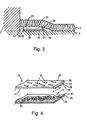
- a carpet fixing fastener used in an embodiment of the present invention is shown in Figures 3 & 4.
- the carpet 1 is laid on the floor 3 against wall 5.
- the carpet is fixed in position by carpet fixing strip 21 which forms an embodiment of this invention.
- a perspective view of carpet fixing fastener 21 is shown in Figure 4.
- the carpet fixing fastener has an elongate upper strip or grip member 23 and a lower or fixing member 25.
- the upper strip 23 is integrally moulded of plastics material.
- On the lower surface 27 of the upper strip 23 are a plurality of hooks 29 which form the hook part of a hook and loop type surface fastener.
- On the upper surface 31 of the lower fastener part 25 are a plurality of loops 33.
- the hooks 29 are releasably engagable with the loops 33 such that members 23, 25 can be releasably engaged with each other.
- the plurality of hooks 29 and the plurality of loops 33 are engaged by pushing the upper strip 23 and the lower fastener part 25 together.
- the upper strip 23 can be peeled away from the lower fastener part 25 but will be strongly held by the lower fastener part if a shearing force is applied in the direction of the arrows S.
- the lower fastener part 25 is provided with a touch sensitive adhesive layer 35 (Figure 4).
- the layer 35 is applied to the lower fastener part 31 during manufacture and covered by a strip of backing paper. To fix the lower fastener part 25 to the floor 3, the strip of backing paper is removed and the lower fastener part 25 is pressed onto the floor 3.
- the upper strip 23 has a plurality of pins 37 integrally formed on its upper surface.
- the pins 37 project away from the upper surface of upper strip 23 and in the direction of a first elongate edge 41 which, in use, is placed closest to wall 5 when the carpet 1 is fitted ( Figure 3).
- the hooks 29 are oriented to best prevent the upper strip 23 moving relative to the lower fastener part 31 under the tension of the carpet.
- the hooks 29 are oriented so that their crooks or open side 28 faces towards a second elongate edge 43 opposite the edge 41.
- the hooks 29 and loops are in shear as denoted by the arrows S.
- Some hooks may be arranged to face in other directions to secure the upper strip against more general movement.
- the carpet fixing fastener is shown with the upper strip 23 engaged with the lower fastener part 25.
- the carpet is fixed as follows.
- the lower fastener part 25 is fixed to the floor 3 at a small distance from the wall 5 by adhesive layer 35.
- the upper strip 23 is then fixed to the floor 3 by pushing the upper strip 23 down onto the lower fastener part 25. This causes the hooks 29 of the upper strip 23 to engage with the loops 33 of the lower fastener part.
- the carpet 1, is then stretched in the usual manner and pressed onto the pins 37 of the upper strip 23.
- the upper strip 23 may peel away from the lower fastener part 25 with the carpet or, be peeled away afterwards so that no exposed pins 37 are left on the floor.
- the lower fastener part 25 may be formed of relative rigid material or it may be flexible depending on the degree of strength required and the desired manner of forming the loops 33.
- a composite structure may be used as is well known in the art.
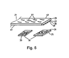
- the lower fastener part 25 can be a plurality of discrete, short lengths 26 which can be used to fix a single elongate upper strip 23 to a floor 3, as illustrated in Figure 5.
Description
- The present invention relates to a method for fixing a carpet to a floor with a carpet fixing strip.
- Fitted carpets are popular in many homes and offices as they provide a safe floor covering which is not prone to slipping. It is known from EP-A-321 978 to hold a carpet in position by providing a loop pile backing layer on the carpet, and a hook fastener part is then fixed to the floor. The carpet is simply pressed down onto the hook fastener part to secure the hooks and loops together. Similar arrangements are described in US-A-5 382 462, W098/03104 and W094/00043. These arrangements require special treatment of the carpet. More typically, the carpet is fixed to the floor or the edges of the room or corridor by a carpet fixing strip or gripper rod. Most commonly, the strip is a flat rod of wood or metal which is nailed or glued to the floor. Pins project from the upper surface of the rod at an angle and the carpet is fixed on the pins.
- This conventional type of strip has its problems. For example, when a fitted carpet is removed from the pins, the carpet fixing strip may also be pulled out of the floor at the same time, damaging the strip. This means that the strip will either need to be re-fixed or replaced which is not desirable.
- Also, when the carpet is removed from the strip, the strip is left attached to the floor with pins sticking out which are dangerous, and the strip may be damaged if it is removed.
- The present invention addresses the above problems. The present invention provides a method of laying a carpet, the method comprising attaching a first part (25) of a surface fastener to a floor (3) on which the carpet (1) is to be laid, providing a strip (23) having on one major surface means (37) for gripping a carpet and on the opposite major surface a second, complementary surface fastener part (29), pressing the second surface fastener part (29) of the strip onto the first surface fastener parts (25) to attach the carpet fixing strip (23) to the floor (3), and engaging the underside of the carpet (1) on the carpet gripping means (37).
- Typically the strip has a plurality of projecting pins or spikes which engage the carpet.
- Preferably the surface fastener is releasably engageable to allow the strip to be removed from the floor so that there are no projecting pins or spikes if the carpet is temporarily removed.
- Preferably, the surface fastener is a hook and loop type fastener. The use of a surface fastener also provides another advantage, in that if either the first (lower) part of the surface fastener or the (upper) strip needs to be replaced for some reason, a complementary fastener part can be easily obtained as an exact match is not required.
- It is more preferable if the surface fastener part on the strip is provided by a hook type fastener. Preferably the strip is made of plastics and preferably, the hook type fastener part is integral with the strip. The integral strip and hook type fastener can be formed by injection molding.
- Preferably, the carpet fixing means is (also) integral with the strip. Again, this can be achieved by injection molding of plastics material.
- As mentioned, typically the carpet fixing means are a plurality of sharp projections e.g. pins which project out of the upper surface of the strip. Usually, the fixing strip is located close to an edge of the carpet and the projections point towards the edge of the carpet. The carpet is fitted to the strip by stretching it and pressing it onto the pins to anchor the carpet. The carpet will try to shrink back. When a hook and loop type fastener is used it is preferable if the hooks are oriented such that the crook portion faces away from the edge of the carpet, if on the strip, or towards the edge of the carpet if on the lower part of the surface fastener. A hook and loop fastening is particularly strong in shear and moulded type hooks can provide a very strong connection.
- Thus, it is particularly preferred if the plurality of sharp projections which project out of the upper surface of the strip point towards a first elongate edge of the strip, the hooks of the hook type fastener are oriented such that hooks generally face towards the opposite elongate edge of the strip.
- The lower part of the surface fastener may be nailed or pinned to the floor. However, it can simply be glued to the floor. It is preferable if it comprises a strip of contact adhesive type material. Thus, no nails need to be used and there is no danger of damaging under floor wiring.
- Also, a single elongate upper strip may engage a plurality of spaced apart lower surface fastener parts of shorter length, or vice versa.
- The present invention will now be described with reference to the accompanying drawings in which:
- Figure 1 is a carpet with a carpet fixing strip according to the prior art;
- Figure 2 is a perspective view of a carpet fixing strip shown in Figure 1;
- Figure 3 is a carpet fixed by a carpet fixing fastener according to the present invention;
- Figure 4 is a perspective view of the carpet fixing fastener of Figure 3; and
- Figure 5 is a carpet fixing fastener in accordance with the present invention with a single upper strip and a plurality of lower faster parts.
-
- A conventional carpet fixing strip or gripper rod is shown in Figure 1. A carpet 1 is laid on top of a floor 3 with the carpet edge adjacent a wall 5. The carpet 1 is held in place by a fixing strip 7. Carpet fixing strip 7 has a flat, elongate wooden rod 9 which is fixed to floor 5 by nails or
pins 11. The fixing strip 7 also has a plurality ofpins 13 which project out of theupper surface 15 of the rod 9. Thepins 13 point towards the wall 5. The carpet 1 is fixed over thepins 13. As the carpet 1 is laid, it is stretched and pressed ontopins 13 to anchor the carpet. A perspective view of the carpet fixing strip of Figure 1 is shown in Figure 2. This construction is well known in the art. - A carpet fixing fastener used in an embodiment of the present invention is shown in Figures 3 & 4. In Figure 3, the carpet 1 is laid on the floor 3 against wall 5. The carpet is fixed in position by
carpet fixing strip 21 which forms an embodiment of this invention. A perspective view ofcarpet fixing fastener 21 is shown in Figure 4. - The carpet fixing fastener has an elongate upper strip or
grip member 23 and a lower orfixing member 25. Theupper strip 23 is integrally moulded of plastics material. On thelower surface 27 of theupper strip 23 are a plurality ofhooks 29 which form the hook part of a hook and loop type surface fastener. On theupper surface 31 of thelower fastener part 25 are a plurality ofloops 33. Thehooks 29 are releasably engagable with theloops 33 such thatmembers hooks 29 and the plurality ofloops 33 are engaged by pushing theupper strip 23 and thelower fastener part 25 together. Theupper strip 23 can be peeled away from thelower fastener part 25 but will be strongly held by the lower fastener part if a shearing force is applied in the direction of the arrows S. - The
lower fastener part 25 is provided with a touch sensitive adhesive layer 35 (Figure 4). Thelayer 35 is applied to thelower fastener part 31 during manufacture and covered by a strip of backing paper. To fix thelower fastener part 25 to the floor 3, the strip of backing paper is removed and thelower fastener part 25 is pressed onto the floor 3. - The
upper strip 23 has a plurality ofpins 37 integrally formed on its upper surface. Thepins 37 project away from the upper surface ofupper strip 23 and in the direction of a firstelongate edge 41 which, in use, is placed closest to wall 5 when the carpet 1 is fitted (Figure 3). - The
hooks 29 are oriented to best prevent theupper strip 23 moving relative to thelower fastener part 31 under the tension of the carpet. Thehooks 29 are oriented so that their crooks oropen side 28 faces towards a secondelongate edge 43 opposite theedge 41. Thus, as the carpet 1 tends to relax back to its original size after being stretched, thehooks 29 and loops are in shear as denoted by the arrows S. Some hooks may be arranged to face in other directions to secure the upper strip against more general movement. - Returning to Figure 3, the carpet fixing fastener is shown with the
upper strip 23 engaged with thelower fastener part 25. The carpet is fixed as follows. Thelower fastener part 25 is fixed to the floor 3 at a small distance from the wall 5 byadhesive layer 35. Theupper strip 23 is then fixed to the floor 3 by pushing theupper strip 23 down onto thelower fastener part 25. This causes thehooks 29 of theupper strip 23 to engage with theloops 33 of the lower fastener part. The carpet 1, is then stretched in the usual manner and pressed onto thepins 37 of theupper strip 23. - When it is desired to remove the carpet for any reason it can be lifted away from the floor. The
upper strip 23 may peel away from thelower fastener part 25 with the carpet or, be peeled away afterwards so that no exposed pins 37 are left on the floor. - The
lower fastener part 25 may be formed of relative rigid material or it may be flexible depending on the degree of strength required and the desired manner of forming theloops 33. A composite structure may be used as is well known in the art. - In Figure 4, a single elongate
upper strip 23 and a single elongatelower fastener part 25 are shown. However, thelower fastener part 25 can be a plurality of discrete,short lengths 26 which can be used to fix a single elongateupper strip 23 to a floor 3, as illustrated in Figure 5.
Claims (7)
- A method of laying a carpet, the method comprising the steps performed in the following order: attaching a first part (25) of a surface fastener to a floor (3) on which the carpet (1) is to be laid, providing a strip (23) having on one major surface means (37) for gripping a carpet and on the opposite major surface a second, complementary surface fastener part (29), pressing the second surface fastener part (29) of the strip onto the first surface fastener part (25) to attach the carpet fixing strip (23) to the floor (3), and engaging the underside of the carpet (1) on the carpet gripping means (37).
- The method as claimed in claim 1, wherein the surface fastener parts (25, 29) are of a hook and loop type.
- The method as claimed in claim 2, wherein hooks (29) are provided on the strip (23).
- The method as claimed in claim 3, wherein the hooks (29) are integrally moulded with the strip (23).
- The method as claimed in claim 3 or 4, wherein the carpet gripping means comprises a plurality of sharp projections (37) which project away from an upper surface of the strip (23) towards a first edge (41) of the strip (23), and wherein the hooks (29) are oriented such that the hooks generally face in the direction of an opposite edge (43) of the strip (23).
- The method as claimed in any preceding claim, wherein the strip (23) is of plastics material.
- The method as claimed in any preceding claim, wherein the first part (25) of the surface fastener is attached to a floor (3) by means of an adhesive strip (35).
Applications Claiming Priority (2)
| Application Number | Priority Date | Filing Date | Title |
|---|---|---|---|
| GB9803785 | 1998-02-23 | ||
| GB9803785A GB2334439A (en) | 1998-02-23 | 1998-02-23 | Carpet fixing strip |
Publications (2)
| Publication Number | Publication Date |
|---|---|
| EP0937431A1 EP0937431A1 (en) | 1999-08-25 |
| EP0937431B1 true EP0937431B1 (en) | 2003-04-16 |
Family
ID=10827445
Family Applications (1)
| Application Number | Title | Priority Date | Filing Date |
|---|---|---|---|
| EP19990301276 Expired - Lifetime EP0937431B1 (en) | 1998-02-23 | 1999-02-23 | Method of laying a carpet with a carpet fixing strip |
Country Status (3)
| Country | Link |
|---|---|
| EP (1) | EP0937431B1 (en) |
| DE (1) | DE69906847T2 (en) |
| GB (1) | GB2334439A (en) |
Families Citing this family (3)
| Publication number | Priority date | Publication date | Assignee | Title |
|---|---|---|---|---|
| GB2367000A (en) * | 2000-09-01 | 2002-03-27 | Gates | A carpet securement strip |
| NZ732263A (en) * | 2014-10-30 | 2020-07-31 | Leblanc Shane S | Modular floor covering seaming apparatus and method |
| US20240117574A1 (en) * | 2022-10-06 | 2024-04-11 | Soccer Park, LLC dba Urban Soccer Park | Apparatus, Systems, and Methods for Turf Trim Strip |
Family Cites Families (8)
| Publication number | Priority date | Publication date | Assignee | Title |
|---|---|---|---|---|
| US3391434A (en) * | 1966-10-07 | 1968-07-09 | American Velcro Inc | Fastening device |
| US3673633A (en) * | 1969-09-23 | 1972-07-04 | James Frebraro | Carpet tack strip |
| US4810546A (en) * | 1984-09-04 | 1989-03-07 | Mclaughlin John J | General floor carpet with flush removable section |
| US4822658B1 (en) * | 1987-12-23 | 1997-06-10 | Joseph R Pacione | Carpet backing and installation system |
| GB9211498D0 (en) * | 1992-05-30 | 1992-07-15 | Centa Antony R | Improvements relating to edging strips for floorcoverings |
| CA2136210C (en) * | 1992-06-30 | 2001-10-02 | Joseph R. Pacione | Carpet construction |
| US5382462A (en) * | 1993-07-28 | 1995-01-17 | Tac-Fast Systems Sa | Carpet tape |
| US20010042350A1 (en) * | 1996-07-19 | 2001-11-22 | Joseph R. Pacione | Covering module and anchor sheet |
-
1998
- 1998-02-23 GB GB9803785A patent/GB2334439A/en not_active Withdrawn
-
1999
- 1999-02-23 DE DE1999606847 patent/DE69906847T2/en not_active Expired - Lifetime
- 1999-02-23 EP EP19990301276 patent/EP0937431B1/en not_active Expired - Lifetime
Also Published As
| Publication number | Publication date |
|---|---|
| GB2334439A (en) | 1999-08-25 |
| EP0937431A1 (en) | 1999-08-25 |
| GB9803785D0 (en) | 1998-04-15 |
| DE69906847T2 (en) | 2004-01-29 |
| DE69906847D1 (en) | 2003-05-22 |
Similar Documents
| Publication | Publication Date | Title |
|---|---|---|
| AU731296B2 (en) | Covering module and anchor sheet | |
| AU767742B2 (en) | Anchor sheet and anchor sheet module | |
| US6460303B1 (en) | Hook and loop anchor sheet module with overlapped edges and sufficient mass to resist buckling | |
| US7185473B2 (en) | Anchor sheet and anchor sheet module | |
| JPS6014741Y2 (en) | Binder material | |
| EP0321978B1 (en) | New carpet backing and installation system | |
| US4321293A (en) | Stair mat | |
| KR20070068368A (en) | System and method for floor covering installation | |
| EP0937431B1 (en) | Method of laying a carpet with a carpet fixing strip | |
| US4750226A (en) | Carpet laying tool and process for using same | |
| US20040181900A1 (en) | Floor covering positioner | |
| US2942289A (en) | Carpet securing means | |
| US4235355A (en) | Device for carrying sheet or panel material | |
| US6969055B1 (en) | Cove base molding clamp | |
| US4918782A (en) | Carpet fastener | |
| US3234581A (en) | Carpet anchoring strip | |
| CA2707905A1 (en) | Non-skid strip | |
| US20020026690A1 (en) | Carpet securement strip and method of use thereof | |
| AU783172B2 (en) | Anchor sheet and anchor sheet module | |
| US3727264A (en) | Carpet anchoring strip | |
| JPH0630437Y2 (en) | Non-slip sheet for rugs | |
| US6385813B1 (en) | Flexible tack strip | |
| JPH07305484A (en) | Execution method of simple floor | |
| JP2004257122A (en) | Rush mat | |
| JP2002253418A (en) | Non-skid sheet for domestic carpet |
Legal Events
| Date | Code | Title | Description |
|---|---|---|---|
| PUAI | Public reference made under article 153(3) epc to a published international application that has entered the european phase |
Free format text: ORIGINAL CODE: 0009012 |
|
| AK | Designated contracting states |
Kind code of ref document: A1 Designated state(s): BE DE ES FR GB IT LU NL SE |
|
| AX | Request for extension of the european patent |
Free format text: AL;LT;LV;MK;RO;SI |
|
| 17P | Request for examination filed |
Effective date: 20000224 |
|
| AKX | Designation fees paid |
Free format text: DE ES FR GB IT |
|
| RBV | Designated contracting states (corrected) |
Designated state(s): BE DE ES FR GB IT LU NL SE |
|
| 17Q | First examination report despatched |
Effective date: 20011022 |
|
| GRAG | Despatch of communication of intention to grant |
Free format text: ORIGINAL CODE: EPIDOS AGRA |
|
| RTI1 | Title (correction) |
Free format text: METHOD OF LAYING A CARPET WITH A CARPET FIXING STRIP |
|
| RTI1 | Title (correction) |
Free format text: METHOD OF LAYING A CARPET WITH A CARPET FIXING STRIP |
|
| GRAG | Despatch of communication of intention to grant |
Free format text: ORIGINAL CODE: EPIDOS AGRA |
|
| GRAH | Despatch of communication of intention to grant a patent |
Free format text: ORIGINAL CODE: EPIDOS IGRA |
|
| GRAH | Despatch of communication of intention to grant a patent |
Free format text: ORIGINAL CODE: EPIDOS IGRA |
|
| GRAA | (expected) grant |
Free format text: ORIGINAL CODE: 0009210 |
|
| AK | Designated contracting states |
Designated state(s): BE DE ES FR GB IT LU NL SE |
|
| PG25 | Lapsed in a contracting state [announced via postgrant information from national office to epo] |
Ref country code: IT Free format text: LAPSE BECAUSE OF FAILURE TO SUBMIT A TRANSLATION OF THE DESCRIPTION OR TO PAY THE FEE WITHIN THE PRESCRIBED TIME-LIMIT;WARNING: LAPSES OF ITALIAN PATENTS WITH EFFECTIVE DATE BEFORE 2007 MAY HAVE OCCURRED AT ANY TIME BEFORE 2007. THE CORRECT EFFECTIVE DATE MAY BE DIFFERENT FROM THE ONE RECORDED. Effective date: 20030416 |
|
| REG | Reference to a national code |
Ref country code: GB Ref legal event code: FG4D |
|
| REF | Corresponds to: |
Ref document number: 69906847 Country of ref document: DE Date of ref document: 20030522 Kind code of ref document: P |
|
| PG25 | Lapsed in a contracting state [announced via postgrant information from national office to epo] |
Ref country code: SE Free format text: LAPSE BECAUSE OF FAILURE TO SUBMIT A TRANSLATION OF THE DESCRIPTION OR TO PAY THE FEE WITHIN THE PRESCRIBED TIME-LIMIT Effective date: 20030716 |
|
| PG25 | Lapsed in a contracting state [announced via postgrant information from national office to epo] |
Ref country code: ES Free format text: LAPSE BECAUSE OF FAILURE TO SUBMIT A TRANSLATION OF THE DESCRIPTION OR TO PAY THE FEE WITHIN THE PRESCRIBED TIME-LIMIT Effective date: 20031030 |
|
| ET | Fr: translation filed | ||
| PLBE | No opposition filed within time limit |
Free format text: ORIGINAL CODE: 0009261 |
|
| STAA | Information on the status of an ep patent application or granted ep patent |
Free format text: STATUS: NO OPPOSITION FILED WITHIN TIME LIMIT |
|
| PG25 | Lapsed in a contracting state [announced via postgrant information from national office to epo] |
Ref country code: LU Free format text: LAPSE BECAUSE OF NON-PAYMENT OF DUE FEES Effective date: 20040223 |
|
| 26N | No opposition filed |
Effective date: 20040119 |
|
| REG | Reference to a national code |
Ref country code: FR Ref legal event code: CA |
|
| PGFP | Annual fee paid to national office [announced via postgrant information from national office to epo] |
Ref country code: NL Payment date: 20090203 Year of fee payment: 11 |
|
| PGFP | Annual fee paid to national office [announced via postgrant information from national office to epo] |
Ref country code: GB Payment date: 20090217 Year of fee payment: 11 |
|
| PGFP | Annual fee paid to national office [announced via postgrant information from national office to epo] |
Ref country code: BE Payment date: 20090225 Year of fee payment: 11 |
|
| PGFP | Annual fee paid to national office [announced via postgrant information from national office to epo] |
Ref country code: FR Payment date: 20090213 Year of fee payment: 11 |
|
| BERE | Be: lapsed |
Owner name: *YKK EUROPE LTD Effective date: 20100228 |
|
| REG | Reference to a national code |
Ref country code: NL Ref legal event code: V1 Effective date: 20100901 |
|
| GBPC | Gb: european patent ceased through non-payment of renewal fee |
Effective date: 20100223 |
|
| REG | Reference to a national code |
Ref country code: FR Ref legal event code: ST Effective date: 20101029 |
|
| PG25 | Lapsed in a contracting state [announced via postgrant information from national office to epo] |
Ref country code: NL Free format text: LAPSE BECAUSE OF NON-PAYMENT OF DUE FEES Effective date: 20100901 Ref country code: FR Free format text: LAPSE BECAUSE OF NON-PAYMENT OF DUE FEES Effective date: 20100301 |
|
| PG25 | Lapsed in a contracting state [announced via postgrant information from national office to epo] |
Ref country code: BE Free format text: LAPSE BECAUSE OF NON-PAYMENT OF DUE FEES Effective date: 20100228 |
|
| PG25 | Lapsed in a contracting state [announced via postgrant information from national office to epo] |
Ref country code: GB Free format text: LAPSE BECAUSE OF NON-PAYMENT OF DUE FEES Effective date: 20100223 |
|
| PGFP | Annual fee paid to national office [announced via postgrant information from national office to epo] |
Ref country code: DE Payment date: 20140417 Year of fee payment: 16 |
|
| REG | Reference to a national code |
Ref country code: DE Ref legal event code: R119 Ref document number: 69906847 Country of ref document: DE |
|
| PG25 | Lapsed in a contracting state [announced via postgrant information from national office to epo] |
Ref country code: DE Free format text: LAPSE BECAUSE OF NON-PAYMENT OF DUE FEES Effective date: 20150901 |