EP0937370B1 - Verfahren zum ersatzschalten von übertragungseinrichtungen zur bidirektionalen übertragung von atm-zellen - Google Patents
Verfahren zum ersatzschalten von übertragungseinrichtungen zur bidirektionalen übertragung von atm-zellen Download PDFInfo
- Publication number
- EP0937370B1 EP0937370B1 EP97945796A EP97945796A EP0937370B1 EP 0937370 B1 EP0937370 B1 EP 0937370B1 EP 97945796 A EP97945796 A EP 97945796A EP 97945796 A EP97945796 A EP 97945796A EP 0937370 B1 EP0937370 B1 EP 0937370B1
- Authority
- EP
- European Patent Office
- Prior art keywords
- switching
- equivalent circuit
- service
- link
- atm cells
- Prior art date
- Legal status (The legal status is an assumption and is not a legal conclusion. Google has not performed a legal analysis and makes no representation as to the accuracy of the status listed.)
- Expired - Lifetime
Links
Images


Classifications
-
- H—ELECTRICITY
- H04—ELECTRIC COMMUNICATION TECHNIQUE
- H04Q—SELECTING
- H04Q11/00—Selecting arrangements for multiplex systems
- H04Q11/04—Selecting arrangements for multiplex systems for time-division multiplexing
- H04Q11/0428—Integrated services digital network, i.e. systems for transmission of different types of digitised signals, e.g. speech, data, telecentral, television signals
- H04Q11/0478—Provisions for broadband connections
-
- H—ELECTRICITY
- H04—ELECTRIC COMMUNICATION TECHNIQUE
- H04B—TRANSMISSION
- H04B1/00—Details of transmission systems, not covered by a single one of groups H04B3/00 - H04B13/00; Details of transmission systems not characterised by the medium used for transmission
- H04B1/74—Details of transmission systems, not covered by a single one of groups H04B3/00 - H04B13/00; Details of transmission systems not characterised by the medium used for transmission for increasing reliability, e.g. using redundant or spare channels or apparatus
-
- H—ELECTRICITY
- H04—ELECTRIC COMMUNICATION TECHNIQUE
- H04L—TRANSMISSION OF DIGITAL INFORMATION, e.g. TELEGRAPHIC COMMUNICATION
- H04L12/00—Data switching networks
- H04L12/54—Store-and-forward switching systems
- H04L12/56—Packet switching systems
- H04L12/5601—Transfer mode dependent, e.g. ATM
- H04L2012/5619—Network Node Interface, e.g. tandem connections, transit switching
-
- H—ELECTRICITY
- H04—ELECTRIC COMMUNICATION TECHNIQUE
- H04L—TRANSMISSION OF DIGITAL INFORMATION, e.g. TELEGRAPHIC COMMUNICATION
- H04L12/00—Data switching networks
- H04L12/54—Store-and-forward switching systems
- H04L12/56—Packet switching systems
- H04L12/5601—Transfer mode dependent, e.g. ATM
- H04L2012/5625—Operations, administration and maintenance [OAM]
- H04L2012/5627—Fault tolerance and recovery
Definitions
- the invention relates to a method according to the preamble of claim 1.
- This known method relates to transmission facilities the synchronous digital hierarchy (SDH).
- SDH synchronous digital hierarchy
- the two end points each contain a monitoring device to detect transmission interference.
- a controllable by the monitoring device Switching device connects a receiving device into one first switching state with the operating route and in one second switching state with the replacement route. Between Control devices of the two end points become control information replaced.
- the switching device is each depending on the local monitoring device from local and in those received from the remote station Tax information contained tax criteria controlled.
- This known method is based on Transmission facilities of the synchronous digital hierarchy relates and not to transmission facilities of the asynchronous Transfer mode (ATM) can be transmitted. Farther this known method arrives at 1 + 1 or 1: 1 structures to use. For more complex structures such as 1: n structures can lead to incorrect connections come.
- ATM asynchronous Transfer mode
- the invention has for its object a method of type mentioned in such a way that cells that be transferred after an asynchronous transfer mode with great security transmitted over a plurality of network nodes can be.
- the invention is based on the in the preamble of the claim 1 specified features by its characteristic Features solved.
- the advantage of the invention is in particular that only a replacement route is provided that a plurality of Operating routes is assigned. About this replacement route the ATM cells of the disrupted operating route are transmitted carried out according to priorities. The circuit is then carried out by the receiving switching device using a logical connection number. In order to the advantage is connected that the connection in the event of an error can be maintained without restriction.
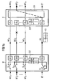
- 1 shows two nodes of an ATM network, which are each designed as a switching device W, E. are. In the present exemplary embodiment, it is assumed that that these exchanges are Cross Connect switches. The usage switching facilities trained in this way means however, no limitation of the invention, other switching devices can also be used.
- 1a is the Transmission of ATM cells from the switching device W pointed to the switching device E, while in Fig. 1b the direction of this connection is disclosed.
- the switching devices W, E are connected to one another via operating lines WE 1 ... WE n (WORKING ENTITY) and only one replacement line PE (PROTECTION ENTITY).
- Switch devices S 0 ... S n (BRIDGE) are also shown, via which the incoming ATM cells and the associated operating lines WE 1 ... WE n are transmitted to the switching device E.
- the ATM cells are transmitted according to an asynchronous transfer mode and each have a header part and an information part.
- the header part is used to record connection information while the information part is used to record useful information.
- the connection information contained in the header is designed as logical information and is usually designed as a virtual path number VPI or virtual channel number VCI.
- FIG. 1 shows selection devices SN, the task of which is to feed the ATM cells transmitted over the operating lines WE 1 ... WE n to the output of the switching device E.
- the selection devices SN are designed as an ATM switching matrix.
- the ATM switching network SN is contained both in the switching device W and in the switching device E.
- monitoring devices ÜE 0 ... ÜE n PROTECTION DOMAIN SINK, PROTECTION DOMAIN SOURCE
- the ATM cells of the connection with the number 1 WT 1 are provided with control information in the monitoring device ÜE 1 of the switching device W, which the monitoring device ÜE 1 takes from the receiving switching device E, before they are transmitted to the switching device E via the operating link WE 1 and checked. This control information can then be used to determine whether the ATM cell has been transmitted correctly or not.
- a total failure (SIGNAL FAIL FOR WORKING ENTITY) of one of the operating lines WE 1 ... WE n can be determined.
- deteriorations in the transmission quality (SIGNAL DEGRADE) can also be determined using known methods.
- the monitoring devices ÜE 1 ... ÜE n close the operating lines WE 1 ... WE n on both sides. Further monitoring devices ÜE 0 are arranged on both ends of the replacement route PE. In the event of a fault, this should serve as a transmission link for the decommissioned operating link WE X. Furthermore, substitute switching protocols ES are transmitted, so that the intactness of the substitute route has top priority.
- each of the switching devices W E are also central Control devices ZST arranged. These include priority tables PG, PL. With the priority tables PL are local priority tables in which the State and priority of the local exchange is saved. The priority tables PG are global priority tables, in the state and Priority of the local but also remaining intermediary institution is. By introducing the priorities achieved that when several equivalent switching requests occur simultaneously It is determined which operating route is replaced. Likewise, are in the priority tables Prioritized the equivalent switching requirements. For example, there is a high priority requirement from a user. Because this equivalent switching request is assigned a high priority it is therefore preferably controlled. One of one of the operating routes controlled equivalent switching request is therefore rejected. The individual priorities are shown in Fig. 4.
- the central control devices ZST of the switching devices W, E exchange information in an equivalent switching protocol ES.
- This protocol is transmitted via the substitute route PE and taken from the assigned monitoring device ÜE 0 of the receiving switching device in each case and fed to the relevant central control device ZST.
- the central control device ZST ensures that the switching devices S 0 ... S n are controlled in a corresponding manner in the event of a fault.
- Information K2 is stored in the protocol ES. Acting it is information about the current conditions of the switching devices. Furthermore there is information K1 stored. This is information related to the generated equivalent switching request. The protocol will each time the equivalent switching request is generated between exchanged the two switching centers. In a Special embodiment of the invention provides that Protocol ES cyclically between the two switching devices transferred to.
- FIG. 1a the transmission of the ATM cells from the switching device W to the switching device E via the operating routes WE 1 ... WE n is shown.
- the associated opposite direction (bidirectional transmission) is explained in FIG. 1b.
- the ATM cells of the switching device W are supplied.
- the ATM cells belong to a variety of connections WT 1 ... WT n .
- the individual connections are distinguished on the basis of the logical connection number VPI entered in the header of the ATM cells.
- the switching devices S 1 ... S n of the switching device W are switched in this (still intact) operating case such that the ATM cells are fed directly to the monitoring devices ÜE 1 ... ÜE n .
- the already mentioned control information is applied to the ATM cells and fed to the monitoring devices ÜE 1 ... ÜE n of the receiving switching device E via the operating route WE 1 ... WE n in question.
- the control information carried is checked there and, if necessary, an error is determined. If the transmission has been carried out correctly, the ATM cells are fed to the ATM switching network SN.
- the logical connection information VPI is evaluated and, in accordance with this evaluation, the ATM cell is forwarded into the ATM network via the output of the switching network SN in question.
- the replacement route PE can remain unused during this time.
- special data EXTRA TRAFFIC
- the switching device S 0 of the switching device W thus takes the positions 1 or 3.
- the special data is also transmitted in ATM cells.
- the monitoring device UE 0 of the switching device W applies control information to the ATM cells in the same way as that which has already been described in the case of the operating lines WE 1 ... WE n .
- the route is also monitored.
- the switching device S 2 of the switching device E is controlled into the remaining operating state, as shown in FIG. 1b.
- the equivalent switching protocol Es is supplied to the switching device W via the equivalent route PE.
- the information K1 and K2 already mentioned are contained in this equivalent switching protocol. It is essential that the local priority logic defines the configuration of the information K1 and the global priority logic defines the position of the switching device S 0 .
- the substitute switching protocol ES is now adopted by the monitoring device ÜE 0 of the switching device E and fed to the central control device ZST of the switching device W. If there are no further higher-priority requirements in the global priority table PG, the switching device S 2 is also controlled and set here in a corresponding manner. Furthermore, the switching device S 0 of the switching device W is also flipped. The new status of the two switching devices S 0 , S 2 is acknowledged by the switching device E and updated in the global priority table PG there. The ATM cells of the connection WT 2 are thus fed to the switching device E via the replacement link PE.
- the selection device SN of the switching device E is designed as an ATM switching matrix.
- the over the replacement route PE-routed ATM cells become this switching matrix mzusuit.
- the logical path number VPI is now Cell head removed and evaluated and through the switching matrix Deutschengeroutet. The activation of switching devices is not necessary thus in this case.
- the selection device is an ATM coupling fee trained so that switching through as required the VPI number is given.
- the switching centers according to Fig. 2 are also - not shown - central control devices with local and global priority tables contain.
- FIG. 3 It is a 1 + 1 structure.
- This structure results from the 1: n structure in that the switching devices S are permanently set and can no longer be controlled via the central control devices ZST. In this way, the ATM cells are also routed via the operating line WE and the replacement line PE even in the event of a fault-free operation.
- the selection device SN is not designed here as an ATM switching matrix, but as a switching device.
- the equivalent switching protocol ES takes a simpler form in this case.
- the information K2 here describes the state of the selection device. Whenever the switching devices S 0 ... S n were controlled in the case of the 1: n structure, the selection device SN is controlled instead in the case of the 1 + 1 structure.
Landscapes
- Engineering & Computer Science (AREA)
- Computer Networks & Wireless Communication (AREA)
- Signal Processing (AREA)
- Data Exchanges In Wide-Area Networks (AREA)
Description
- Figur 1
- das erfindungsgemäße Verfahren zur bidirektionalen Übertragung von ATM-Zellen in einer 1:n-Struktur,
- Figur 2
- eine spezielle Ausgestaltung des erfindungsgemäßen Verfahrens in einer 1:1-Struktur,
- Figur 3
- eine weitere spezielle Ausgestaltung des erfindungsgemäßen Verfahrens in einer 1+1-Struktur.
- Figur 4
- die verwendeten Prioritäten, nach deren Maßgabe die Ersatzschaltung erfolgt.
Claims (11)
- Verfahren zum Ersatzschalten von Übertragungseinrichtungen zur bidirektionalen Übertragung von ATM-Zellen, mit
zwei Vermittlungseinrichtungen (W, E) die jeweils einen aus einer Mehrzahl von Betriebsstrecken (WE1...WEn) gebildeten Übertragungsabschnitt abschließen, und die Informationen in ATM-Zellen über die Mehrzahl von Betriebsstrecken (WE1...WEn) der jeweils empfangenden Vermittlungseinrichtung (W, E) zuführen sowie mit Überwachungseinrichtungen (ÜE1...ÜEn), die jeweils am Ende einer Betriebsstrecke angeordnet sind und von der eine Störung der Betriebsstrecke ermittelt wird,
dadurch gekennzeichnet, daß zusätzlich eine Ersatzstrecke (PE) zwischen den beiden Vermittlungseinrichtungen (W, E) vorgesehen wird, über die im Falle einer Störung auf einer der Betriebsstrecken (WE1..WEn) die hierüber übertragen ATM-Zellen nach Maßgabe von Prioritätskriterien sowie von im Zellenkopf der ATM-Zellen enthaltenen logischen Verbindungsinformationen übertragen und den weiteren Einrichtungen des ATM-Netzes zugeführt werden, wobei den Betriebsstrecken (WE1...WEn) sowie der Ersatzstrecke (PE) eine Priorität zugewiesen wird. - Verfahren nach Anspruch 1,
dadurch gekennzeichnet, daß im Ersatzschaltefall eine Ersatzschalteanforderung (K1) generiert wird, der weitere Prioritäten zugewiesen werden. - Verfahren nach Anspruch 1,
dadurch gekennzeichnet, daß die logische Verbindungsinformation die Nummer des virtuellen Pfades (VPI) ist. - Verfahren nach Anspruch 1 bis 3,
dadurch gekennzeichnet, daß Prioritätstabellen (PL, PG) vorgesehen werden, in der die Prioritäten festgelegt werden. - Verfahren nach einem der Ansprüche 1 bis 4,
dadurch gekennzeichnet, daß die Ersatzschaltung durch Ansteuern einer in der sendenden Vermittlungseinrichtung enthaltenden Schaltvorrichtung (S0...Sn) sowie unter Verwendung einer in der empfangenden Vermittlungseinrichtung angeordneten Selektionseinrichtung (SN) erfolgt. - Verfahren nach einem der Ansprüche 5,
dadurch gekennzeichnet, daß die Selektionseinrichtung (SN) als ATM-Koppelfeld ausgebildet ist. - Verfahren nach einem der vorstehenden Ansprüche,
dadurch gekennzeichnet, daß über die Ersatzstrecke (PE) in betriebsstörungsfreien Zeiten Sonderdaten übertragen wird. - Verfahren nach einem der vorstehenden Ansprüche,
dadurch gekennzeichnet, daß bei Eintreffen einer Ersatzschalteanforderung in der empfangenden Vermittlungseinrichtung ein Ersatzschalteprotokoll (ES) generiert wird, das lediglich einmal über die Ersatzstrecke (PE) der verbleibenden Vermittlungseinrichtung zugeführt wird. - Verfahren nach einem der vorstehenden Ansprüche,
dadurch gekennzeichnet, daß Totalaufall und Verschlechterung einer Betriebsstrecke in der Überwachungseinrichtung der empfangenden Vermittlungseinrichtung ermittelt werden. - Verfahren nach Anspruch 5,
dadurch gekennzeichnet, daß Schaltvorrichtung fest einstellbar ist. - Verfahren nach einem der vorstehenden Ansprüche,
dadurch gekennzeichnet, daß die Vermittlungseinrichtungen als Crossconnect- Schalteinrichtungen ausgebildet sind.
Applications Claiming Priority (3)
| Application Number | Priority Date | Filing Date | Title |
|---|---|---|---|
| DE19646016 | 1996-11-07 | ||
| DE19646016A DE19646016C2 (de) | 1996-11-07 | 1996-11-07 | Verfahren zum Ersatzschalten von Übertragungseinrichtungen zur bidirektionalen Übertragung von ATM-Zellen |
| PCT/DE1997/002495 WO1998020699A1 (de) | 1996-11-07 | 1997-10-27 | Verfahren zum ersatzschalten von übertragungseinrichtungen zur bidirektionalen übertragung von atm-zellen |
Publications (2)
| Publication Number | Publication Date |
|---|---|
| EP0937370A1 EP0937370A1 (de) | 1999-08-25 |
| EP0937370B1 true EP0937370B1 (de) | 2004-06-09 |
Family
ID=7810980
Family Applications (1)
| Application Number | Title | Priority Date | Filing Date |
|---|---|---|---|
| EP97945796A Expired - Lifetime EP0937370B1 (de) | 1996-11-07 | 1997-10-27 | Verfahren zum ersatzschalten von übertragungseinrichtungen zur bidirektionalen übertragung von atm-zellen |
Country Status (8)
| Country | Link |
|---|---|
| US (1) | US6580688B1 (de) |
| EP (1) | EP0937370B1 (de) |
| JP (1) | JP3377216B2 (de) |
| AU (1) | AU728723B2 (de) |
| CA (1) | CA2270657C (de) |
| DE (2) | DE19646016C2 (de) |
| ES (1) | ES2221072T3 (de) |
| WO (1) | WO1998020699A1 (de) |
Families Citing this family (14)
| Publication number | Priority date | Publication date | Assignee | Title |
|---|---|---|---|---|
| DE19717584C2 (de) * | 1997-04-25 | 1999-02-11 | Siemens Ag | Verfahren zum Ersatzschalten von Übertragungseinrichtungen zur bidirektionalen Übertragung von ATM-Zellen |
| CA2328246A1 (en) | 1998-04-17 | 1999-10-28 | Siemens Aktiengesellschaft | Method for standby circuiting of assemblies in 1:n redundancy |
| JP3350926B2 (ja) * | 1999-03-30 | 2002-11-25 | 日本電気株式会社 | Ponのプロテクション切り換え方法および装置 |
| EP1126742A1 (de) * | 2000-02-15 | 2001-08-22 | Siemens Aktiengesellschaft | Verfahren zum Ersatzschalten von Übertragungseinrichtungen in MPLS-Netzen |
| EP1126741A1 (de) * | 2000-02-15 | 2001-08-22 | Siemens Aktiengesellschaft | Verfahren zum Ersatzschalten von Übertragungseinrichtungen in MPLS-Netzen |
| US20020038461A1 (en) * | 2000-04-19 | 2002-03-28 | Gerard White | Radio-frequency communications redundancy |
| DE10063390A1 (de) * | 2000-12-19 | 2002-06-20 | Bosch Gmbh Robert | Verfahren zur Steuerung von Verbindungen in einem Kommunikationssystem hierzu |
| US6963533B2 (en) * | 2000-12-29 | 2005-11-08 | Nokia Inc. | Method and system for establishing link bit rate for inverse multiplexed data streams |
| US7046623B2 (en) * | 2000-12-29 | 2006-05-16 | Nokia Inc. | Fault recovery system and method for inverse multiplexed digital subscriber lines |
| US6766482B1 (en) | 2001-10-31 | 2004-07-20 | Extreme Networks | Ethernet automatic protection switching |
| US7505486B2 (en) * | 2002-11-19 | 2009-03-17 | Hewlett-Packard Development Company, L.P. | Degradable network data path transmission scheme |
| CN100353716C (zh) * | 2003-01-22 | 2007-12-05 | 华为技术有限公司 | 一种建立和删除分叉标记交换路径的方法 |
| US20050058063A1 (en) * | 2003-09-15 | 2005-03-17 | Dell Products L.P. | Method and system supporting real-time fail-over of network switches |
| AT510757B1 (de) * | 2010-11-15 | 2014-01-15 | Siemens Ag Oesterreich | System zur fehlersicheren und redundanten übertragung von komplexen daten |
Family Cites Families (10)
| Publication number | Priority date | Publication date | Assignee | Title |
|---|---|---|---|---|
| JPH04154242A (ja) * | 1990-10-17 | 1992-05-27 | Nec Corp | ネットワーク障害回復方式 |
| DE4128938C2 (de) * | 1991-08-30 | 1995-12-14 | Siemens Ag | Verfahren zum Einrichten von virtuellen Verbindungen in Paketvermittlungsnetzen |
| JP3071007B2 (ja) * | 1991-10-22 | 2000-07-31 | 富士通株式会社 | 通信ネットワーク制御方式 |
| EP0700605B1 (de) * | 1993-05-28 | 1998-08-05 | Siemens Aktiengesellschaft | Verfahren zur ersatzschaltung für eine übertragungseinrichtung zur bidirektionalen übertragung von digitalsignalen und anordnung zur durchführung des verfahrens |
| DE4331577C2 (de) * | 1993-09-16 | 1995-12-07 | Siemens Ag | Verfahren und Schaltungsanordnung zum Übertragen von Nachrichtenzellen über redundante virtuelle Pfadpaare eines ATM-Kommunikationsnetzes |
| US5412652A (en) * | 1993-09-24 | 1995-05-02 | Nec America, Inc. | Sonet ring subnetwork management method |
| FI98772C (fi) * | 1994-02-28 | 1997-08-11 | Nokia Telecommunications Oy | Menetelmä pakettimuotoisen datayhteyden reitin vaihtamiseksi |
| JP3623997B2 (ja) * | 1994-12-28 | 2005-02-23 | 富士通株式会社 | デジタル交換機間中継方式及びデジタル交換機 |
| JPH0974412A (ja) * | 1995-09-04 | 1997-03-18 | Fujitsu Ltd | Atm交換網のapsシステム |
| US5808920A (en) * | 1996-03-19 | 1998-09-15 | Digital Lightwave, Inc. | Communications line test apparatus with an improved graphical user interface |
-
1996
- 1996-11-07 DE DE19646016A patent/DE19646016C2/de not_active Expired - Fee Related
-
1997
- 1997-10-27 DE DE59711713T patent/DE59711713D1/de not_active Expired - Fee Related
- 1997-10-27 AU AU51166/98A patent/AU728723B2/en not_active Ceased
- 1997-10-27 EP EP97945796A patent/EP0937370B1/de not_active Expired - Lifetime
- 1997-10-27 JP JP52093898A patent/JP3377216B2/ja not_active Expired - Fee Related
- 1997-10-27 US US09/297,157 patent/US6580688B1/en not_active Expired - Fee Related
- 1997-10-27 CA CA002270657A patent/CA2270657C/en not_active Expired - Fee Related
- 1997-10-27 ES ES97945796T patent/ES2221072T3/es not_active Expired - Lifetime
- 1997-10-27 WO PCT/DE1997/002495 patent/WO1998020699A1/de not_active Ceased
Also Published As
| Publication number | Publication date |
|---|---|
| WO1998020699A1 (de) | 1998-05-14 |
| DE19646016A1 (de) | 1998-05-20 |
| DE59711713D1 (de) | 2004-07-15 |
| DE19646016C2 (de) | 1999-10-14 |
| JP2000512112A (ja) | 2000-09-12 |
| AU5116698A (en) | 1998-05-29 |
| CA2270657A1 (en) | 1998-05-14 |
| EP0937370A1 (de) | 1999-08-25 |
| JP3377216B2 (ja) | 2003-02-17 |
| US6580688B1 (en) | 2003-06-17 |
| ES2221072T3 (es) | 2004-12-16 |
| AU728723B2 (en) | 2001-01-18 |
| CA2270657C (en) | 2005-01-11 |
Similar Documents
| Publication | Publication Date | Title |
|---|---|---|
| DE69513663T2 (de) | Atm-koppelfeld mit doppeltem vermittlungsebenenbetrieb | |
| DE19532422C1 (de) | Lokales, nach dem asynchronen Transfermodus (ATM) arbeitendes Netzwerk mit wenigstens zwei Ringsystemen | |
| DE19646016C2 (de) | Verfahren zum Ersatzschalten von Übertragungseinrichtungen zur bidirektionalen Übertragung von ATM-Zellen | |
| EP1130853A1 (de) | Schaltungsanordnung zum Ersatzschalten von Übertragungseinrichtungen in MPLS-Pakete führende Ringarchitekturen | |
| EP1262084B1 (de) | Verfahren zum ersatzschalten von übertragungseinrichtungen in mpls-netzen | |
| EP0448734B1 (de) | Schaltungsanordnung für die Routineprüfung einer Schnittstelle zwischen Anschlussgruppen und dem Koppelnetz eines PCM-Fernmeldevermittlungssystems | |
| EP1010303B1 (de) | Kommunikationseinrichtung für die übertragung von nachrichtensignalen | |
| EP0857002A2 (de) | Verfahren zum Ersatzschalten von Übertragungseinrichtung in Ringarchitekturen zur bidirektionalen Übertragung von ATM-Zellen | |
| EP1410576B1 (de) | Verfahren zum ersatzschalten von übertragungseinrichtungen in mpls-pakete führende ringarchitekturen | |
| EP1097540B1 (de) | Verfahren und vorrichtung zum optimieren der übertragungs- und ausfallsicherheit in hochbitratigen datennetzen | |
| EP1425872B1 (de) | Verfahren und Kommunikationseinrichtung zur Realisierung zumindest einer ausfallsicheren Kommunikationsbeziehung | |
| DE19717584C2 (de) | Verfahren zum Ersatzschalten von Übertragungseinrichtungen zur bidirektionalen Übertragung von ATM-Zellen | |
| EP1016238A1 (de) | Redundanzsystem mit "1:n" und "1:1" redundanz für ein asn-system | |
| EP0732828B1 (de) | Redundanzoptimiertes Kommunikationsnetz für die Übertragung von Nachrichtensignalen | |
| EP1126741A1 (de) | Verfahren zum Ersatzschalten von Übertragungseinrichtungen in MPLS-Netzen | |
| EP0857003A2 (de) | Schaltungsanordnung zum Ersatzschalten von Übertragungseinrichtungen in Ringarchitekturen zur bidirektionalen Übertragung von ATM-Zellen | |
| EP1359693A2 (de) | Verfahren zum Schützen von Datensignalen, die über Lichtwellenleiter übertragen werden | |
| DE10152339B4 (de) | Verfahren und Kommunikationseinrichtung zur Realisierung zumindest einer ausfallsicheren Kommunikationsbeziehung durch eine in einem Kommunikationsnetz angeordnete Kommunikationseinrichtung | |
| EP0984658B1 (de) | Telekommunikationssystem mit Vermittlungseinrichtung und Datenkonzentrator für den Zugang zum Internet | |
| DE19926569A1 (de) | Verfahren zum Betrieb und Aufbau eines Kommunikationsnetzes mit Selbstheilungsmechanismen für virtuelle Verbindungen in SONET/SDH basierten Doppelringen und verketteten Doppelringen |
Legal Events
| Date | Code | Title | Description |
|---|---|---|---|
| PUAI | Public reference made under article 153(3) epc to a published international application that has entered the european phase |
Free format text: ORIGINAL CODE: 0009012 |
|
| 17P | Request for examination filed |
Effective date: 19990505 |
|
| AK | Designated contracting states |
Kind code of ref document: A1 Designated state(s): BE DE ES FR GB IT |
|
| GRAP | Despatch of communication of intention to grant a patent |
Free format text: ORIGINAL CODE: EPIDOSNIGR1 |
|
| GRAS | Grant fee paid |
Free format text: ORIGINAL CODE: EPIDOSNIGR3 |
|
| GRAA | (expected) grant |
Free format text: ORIGINAL CODE: 0009210 |
|
| AK | Designated contracting states |
Kind code of ref document: B1 Designated state(s): BE DE ES FR GB IT |
|
| REG | Reference to a national code |
Ref country code: GB Ref legal event code: FG4D Free format text: NOT ENGLISH |
|
| GBT | Gb: translation of ep patent filed (gb section 77(6)(a)/1977) |
Effective date: 20040609 |
|
| REF | Corresponds to: |
Ref document number: 59711713 Country of ref document: DE Date of ref document: 20040715 Kind code of ref document: P |
|
| PG25 | Lapsed in a contracting state [announced via postgrant information from national office to epo] |
Ref country code: BE Free format text: LAPSE BECAUSE OF NON-PAYMENT OF DUE FEES Effective date: 20041031 |
|
| REG | Reference to a national code |
Ref country code: ES Ref legal event code: FG2A Ref document number: 2221072 Country of ref document: ES Kind code of ref document: T3 |
|
| ET | Fr: translation filed | ||
| PLBE | No opposition filed within time limit |
Free format text: ORIGINAL CODE: 0009261 |
|
| STAA | Information on the status of an ep patent application or granted ep patent |
Free format text: STATUS: NO OPPOSITION FILED WITHIN TIME LIMIT |
|
| BERE | Be: lapsed |
Owner name: SIEMENS A.G. Effective date: 20041031 |
|
| PG25 | Lapsed in a contracting state [announced via postgrant information from national office to epo] |
Ref country code: DE Free format text: LAPSE BECAUSE OF NON-PAYMENT OF DUE FEES Effective date: 20050503 |
|
| 26N | No opposition filed |
Effective date: 20050310 |
|
| PGFP | Annual fee paid to national office [announced via postgrant information from national office to epo] |
Ref country code: GB Payment date: 20061012 Year of fee payment: 10 |
|
| PGFP | Annual fee paid to national office [announced via postgrant information from national office to epo] |
Ref country code: IT Payment date: 20061031 Year of fee payment: 10 |
|
| PGFP | Annual fee paid to national office [announced via postgrant information from national office to epo] |
Ref country code: ES Payment date: 20061115 Year of fee payment: 10 |
|
| BERE | Be: lapsed |
Owner name: *SIEMENS A.G. Effective date: 20041031 |
|
| GBPC | Gb: european patent ceased through non-payment of renewal fee |
Effective date: 20071027 |
|
| REG | Reference to a national code |
Ref country code: FR Ref legal event code: ST Effective date: 20080630 |
|
| PGFP | Annual fee paid to national office [announced via postgrant information from national office to epo] |
Ref country code: FR Payment date: 20061018 Year of fee payment: 10 |
|
| PG25 | Lapsed in a contracting state [announced via postgrant information from national office to epo] |
Ref country code: GB Free format text: LAPSE BECAUSE OF NON-PAYMENT OF DUE FEES Effective date: 20071027 |
|
| REG | Reference to a national code |
Ref country code: ES Ref legal event code: FD2A Effective date: 20071029 |
|
| PG25 | Lapsed in a contracting state [announced via postgrant information from national office to epo] |
Ref country code: FR Free format text: LAPSE BECAUSE OF NON-PAYMENT OF DUE FEES Effective date: 20071031 Ref country code: ES Free format text: LAPSE BECAUSE OF NON-PAYMENT OF DUE FEES Effective date: 20071029 |
|
| PG25 | Lapsed in a contracting state [announced via postgrant information from national office to epo] |
Ref country code: IT Free format text: LAPSE BECAUSE OF NON-PAYMENT OF DUE FEES Effective date: 20071027 |