EP0936719B1 - Battery pack and battery system - Google Patents
Battery pack and battery system Download PDFInfo
- Publication number
- EP0936719B1 EP0936719B1 EP99300904A EP99300904A EP0936719B1 EP 0936719 B1 EP0936719 B1 EP 0936719B1 EP 99300904 A EP99300904 A EP 99300904A EP 99300904 A EP99300904 A EP 99300904A EP 0936719 B1 EP0936719 B1 EP 0936719B1
- Authority
- EP
- European Patent Office
- Prior art keywords
- battery
- battery pack
- data
- charging
- electronic device
- Prior art date
- Legal status (The legal status is an assumption and is not a legal conclusion. Google has not performed a legal analysis and makes no representation as to the accuracy of the status listed.)
- Expired - Lifetime
Links
Images


Classifications
-
- H—ELECTRICITY
- H02—GENERATION; CONVERSION OR DISTRIBUTION OF ELECTRIC POWER
- H02J—CIRCUIT ARRANGEMENTS OR SYSTEMS FOR SUPPLYING OR DISTRIBUTING ELECTRIC POWER; SYSTEMS FOR STORING ELECTRIC ENERGY
- H02J7/00—Circuit arrangements for charging or depolarising batteries or for supplying loads from batteries
- H02J7/0068—Battery or charger load switching, e.g. concurrent charging and load supply
-
- H—ELECTRICITY
- H02—GENERATION; CONVERSION OR DISTRIBUTION OF ELECTRIC POWER
- H02J—CIRCUIT ARRANGEMENTS OR SYSTEMS FOR SUPPLYING OR DISTRIBUTING ELECTRIC POWER; SYSTEMS FOR STORING ELECTRIC ENERGY
- H02J7/00—Circuit arrangements for charging or depolarising batteries or for supplying loads from batteries
- H02J7/00032—Circuit arrangements for charging or depolarising batteries or for supplying loads from batteries characterised by data exchange
- H02J7/00036—Charger exchanging data with battery
-
- H—ELECTRICITY
- H02—GENERATION; CONVERSION OR DISTRIBUTION OF ELECTRIC POWER
- H02J—CIRCUIT ARRANGEMENTS OR SYSTEMS FOR SUPPLYING OR DISTRIBUTING ELECTRIC POWER; SYSTEMS FOR STORING ELECTRIC ENERGY
- H02J7/00—Circuit arrangements for charging or depolarising batteries or for supplying loads from batteries
- H02J7/00047—Circuit arrangements for charging or depolarising batteries or for supplying loads from batteries with provisions for charging different types of batteries
-
- Y—GENERAL TAGGING OF NEW TECHNOLOGICAL DEVELOPMENTS; GENERAL TAGGING OF CROSS-SECTIONAL TECHNOLOGIES SPANNING OVER SEVERAL SECTIONS OF THE IPC; TECHNICAL SUBJECTS COVERED BY FORMER USPC CROSS-REFERENCE ART COLLECTIONS [XRACs] AND DIGESTS
- Y02—TECHNOLOGIES OR APPLICATIONS FOR MITIGATION OR ADAPTATION AGAINST CLIMATE CHANGE
- Y02E—REDUCTION OF GREENHOUSE GAS [GHG] EMISSIONS, RELATED TO ENERGY GENERATION, TRANSMISSION OR DISTRIBUTION
- Y02E60/00—Enabling technologies; Technologies with a potential or indirect contribution to GHG emissions mitigation
- Y02E60/10—Energy storage using batteries
Definitions
- the present invention relates to a battery pack, an electronic device which uses such a battery pack and a charger for charging such a battery pack.
- US-A-5,541,489 discloses a "smart battery system” having a “smart battery”, a charger and a system host which is for example a computer, video camera or cellular phone.
- the smart battery has a rechargeable battery, a nonvolatile memory, and circuits for sensing battery parameters, e.g. current, voltage and environment e.g. temperature and time.
- battery parameters e.g. current, voltage and environment e.g. temperature and time.
- a processor stores battery-specific characteristics in the memory.
- the processor receives battery current, voltage and environment information from the sensors and the characteristics from the memory to determine battery capacity, run-time and other data.
- Such data is provided to the charge and system host.
- EP-A-0 750 215 discloses a battery pack including a memory means for storing data indicating the remaining capacity of the battery pack.
- the camera body When the secondary battery pack is mounted to a camera body, the camera body is powered and an information transmission means is activated to read the remaining capacity data of the secondary battery, stored in said memory means through a terminal. Said data is transferred from the transmission means to a calculation circuit which thereafter continuously calculates the remaining capacity of the secondary battery pack is detached. The remaining capacity data obtained in said calculation circuit is constantly recorded, as new data, in the memory means of the battery through the transmission means and the terminal. Consequently, even when the secondary battery pack is disconnected from the camera body, the remaining capacity data immediately before said disconnection is stored in said pack itself.
- EP-A-0 794 438 discloses a battery pack for use with electronic equipment, for example a video camera.
- the electronic equipment has the function of displaying the battery residual quantity for displaying the usable residual time of the battery pack.
- the equipment is designed to cope with different types, including future versions, of battery.
- the battery pack outputs information on the residual battery capacity, charging/discharging current detection information and the battery cell voltage detection information.
- the video camera includes a micro-computer having a communication circuit for receiving the information from the battery pack, a calculation circuit for calculating the current residual battery capacity based on the information from the battery pack received by the communication circuit, and a display control circuit.
- a display device is supplied with a display signal corresponding to the results of calculations by the calculation circuit of the micro-computer so as to display the residual battery capacity based on the display signal.
- the present applicant has previously proposed a charging device which is, upon charging a battery pack, capable of indicating a drive possible time of an electronic device using a battery cell being charged and its current charging capacity as shown in FIGS. 1 to 4 .
- reference numeral 1 denotes a charging device housed in an electronic device such as a video tape recorder having a built-in camera (hereinafter referred to as a video camera) or the like.
- reference numeral 2 denotes an AC adapter 2 connected to a commercially-available power supply to supply the power to the video camera and the charging device 1.
- This charging device 1 includes a charging circuit 3, a calculation processing microcomputer 5 and a display device 6 and this charging circuit 3 charges a battery cell 20 (see FIG. 2 ) of a battery pack 4 that is used to drive the video camera when a user carries the video camera.
- the charging circuit 3 is arranged as is well known in the prior art.
- This battery pack 4 includes at least a battery calculation processing means 4a for obtaining battery cell voltage detection information and charging current cumulated amount information a communication processing means 4b for communicating each of the information.
- FIG. 2 An example of this battery pack 4 is shown in FIG. 2 .
- a positive electrode of the battery cell 20 of the battery pack 4 is connected to a plus terminal TM1 of this battery pack 4, and a negative electrode of the battery cell 20 is connected through a current detection resistor R7 to a minus terminal TM2 of this battery pack 4.
- the plus terminal TM1 and the minus terminal TM2 are respectively connected to a plus terminal and a minus terminal at the output side of the charging circuit 3 of the charging device 1.
- the power from a microcomputer power supply 16 including a series regulator, a reset circuit or the like is supplied to a microcomputer 10 housed in the battery pack 4.
- the microcomputer 10 is operated by the power supplied from this microcomputer power supply 16.
- the microcomputer 10 has functions of the battery calculation processing means 4a and communication processing means 4b.
- a charging current detection input terminal D11 of this microcomputer 10 is connected to an output terminal of an operational amplifier 13 provided to detect a charging current.
- a discharging current detection input terminal D12 thereof is connected to an output terminal of an operational amplifier 14 provided to detect a discharging current. Both the operational amplifiers 13 and 14 detect charging and discharging currents based on the voltage difference across the current detecting resistor R7.
- An interrupt input terminal of the microcomputer 10 is connected to an output terminal of a 2-input NAND gate 15 having two input terminals connected to the respective output terminals of the operational amplifiers 13 and 14. Further, the output terminal of the 2-input NAND gate 15 is connected through a pull-up resistor R8, for example, to a power supply terminal. Also, a temperature detection input terminal of the microcomputer 10 is connected to an output terminal of a temperature sensor 19 which detects an ambient temperature of the battery cell 20. A voltage detection input terminal thereof is connected to an output terminal of a voltage detection circuit 18 which is used to detect a terminal voltage of the battery cell 20. A ground terminal GND thereof is connected to the negative electrode of the battery cell 20. An output and input terminal TMC used to communicate with the calculation processing microcomputer 5, which comprises a computation means of the charging device 1 of the video camera as will be described later on, is connected to buffer amplifiers 11 and 12.
- analog input terminals such as the charging current detection input terminal D11, the discharging current detection input terminal D12, the temperature detection input terminal, the voltage detection input terminal and so on are all A/D input ports. Therefore, the microcomputer 10 houses an A/D converter for converting these analog input into digital form.
- the voltage detection circuit 18 is formed of a voltage-dividing resistor comprising resistors R9 and R10. A voltage across the battery cell 20 is detected by this voltage-dividing resistor. A voltage detection value from this voltage detection circuit 18 is supplied to the voltage detection input terminal of the microcomputer 10. Accordingly, the microcomputer 10 is able to learn the terminal voltage across the battery cell 20 based on the voltage detection value supplied to this voltage detection input terminal from the voltage detection circuit 18.
- the temperature sensor 19 is comprised of a suitable device such as a temperature detection thermistor or the like.
- the temperature sensor 19 is disposed in the vicinity of or in contact with the battery cell 20, and a temperature detection value of this temperature sensor 19 is supplied to the temperature detection input terminal of the microcomputer 10. Accordingly, the microcomputer 10 is able to learn a temperature of the battery cell 20 based on the temperature detection value supplied to this temperature detection input terminal.
- a non-inverting input terminal of the operational amplifier 13 is connected through a resistor R3 to the negative electrode of the battery cell 20, and an inverting input terminal thereof is connected through a current voltage detection resister R7 to the negative electrode of the battery cell 20 and also to an amplification factor setting negative feedback resistor R2 and a resistor R1. Accordingly, the operational amplifier 13 outputs from its output terminal a voltage value which results from amplifying a current value (current value flowing upon charging) flowing into the battery pack 4 in response to a ratio (R2/R1) of resistance values of the resistors R1 and R2.
- a non-inverting input terminal of the operational amplifier 14 is connected through a resistor R6 and the current voltage detection resistor R7 to the negative electrode of the battery cell 20.
- An inverting input terminal thereof is connected to a negative feedback resistor R5 and a resistor R4. Accordingly, the operational amplifier 14 outputs from its output terminal a voltage value which results from amplifying a current value (current value flowing upon discharging) flowing into the battery pack 4 in response to a ratio (R5/R4) of resistance values of the resistors R4 and R5.
- a transistor switch Tr1 is comprised of a field-effect transistor, for example, and whose gate is connected to a switching control output terminal SW1 of the microcomputer 10.
- the resistor R1 is connected between the drain and the source of this transistor switch Tr1. Accordingly, when the level of the signal from the switching control output terminal SW1 of the microcomputer 10 goes to a high (H) level, for example, the transistor switch Tr1 is turned ON, whereby the resistance value based on this resistor R1 becomes approximately 0 (there is only the internal resistor of the transistor switch Tr1), thereby resulting in the amplification factor (amplifier gain) of the operational amplifier 13 whose amplification factor is set in response to the ratio (R2/R1) of the resistance values of the resistors R1 and R2 being increased.
- a transistor switch Tr1 is turned OFF, whereby the amplification factor of this operational amplifier 13 becomes such one corresponding to the ratio (R2/R1) of the resistance values of the resistors R1 and R2, i.e. amplification factor (amplifier gain) smaller than that obtained when the transistor switch Tr1 is placed in the ON state.
- a transistor switch Tr2 is comprised of a field-effect transistor, for example, and whose gate is connected to a switching control output terminal SW2 of the microcomputer 10.
- the resistor R4 is connected between the drain and the source of the transistor switch Tr2.
- the transistor switch Tr2 when the level of the signal from the switching control output terminal SW2 of the microcomputer 10 goes to a high (H) level, for example, the transistor switch Tr2 is turned ON, thereby resulting in a resistance value of the resistor R4 being decreased to approximately 0 (there is only the internal resistance of the transistor switch Tr2). Thus, the amplification factor (amplifier gain)of the operational amplifier 14 increases.
- the transistor switch Tr2 when the level of the signal from the switching control output terminal SW2 of the microcomputer 10 goes to a low (L) level, for example, the transistor switch Tr2 is turned OFF, thereby resulting in the amplification factor (amplifier gain)of the operational amplifier 14 being decreased.
- the microcomputer 10 constantly monitors the levels of the charging current detection input terminal D11 and the discharging current detection input terminal D12 in the normal operation mode (Run mode). When the levels of these terminals D11, D12 are higher than the constant level, the microcomputer 10 causes the signal levels of the switching control output terminals SW1 and SW2 to be held at low level. Thus, the transistor switches Tr1 and Tr2 are both turned OFF, thereby resulting in the amplifier gains of the operational amplifiers 13 and 14 being decreased. Therefore, the microcomputer 10 in the normal operation mode (Run mode) becomes able to measure a current value (current value flowing in the charging or current value flowing in the discharging) flowing into the battery pack 4 by using the output values obtained from the operational amplifiers 13 and 14 whose amplifier gains are decreased. Accordingly, if the current values in the charging and the discharging are obtained, then it becomes possible to calculate the charging and discharging current cumulated value.
- data of a battery cell voltage V, a charging current I, a charging current cumulated amount Q and temperature dependence coefficients h1(T) and h2(T) from the battery pack 4 are supplied to the calculation processing microcomputer 5 comprising the computing means of this charging device 1.
- This calculation processing microcomputer 5 is operated in accordance with a flowchart shown in FIG. 4 .
- This calculation processing microcomputer 5 computes the charging capacity of the battery cell 20 of the charged battery pack 4 being charged and displays a computed charging capacity on the display device 6 which will be described later on. At that same time, this calculation processing microcomputer 5 computes a time during which the present charging capacity can run the video camera using this battery pack 4, and displays this computed time on the display device 6.
- This display device 6 includes a present charging capacity indicator 30 comprising 5-step indicators a, b, c, d, e as shown in FIG. 3 .
- the uppermost portion in the indicator upon charging is blinked.
- the indicator a is blinked; when the charging capacity ranges from 20 to 40%, the indicator a is lit and at the same time, the indicator b is blinked; when the charging capacity ranges from 40 to 60%, the indicators a and b are lit and at the same time, the indicator c is blinked; when the charging capacity ranges from 60 to 80%, the indicators a, b, c are lit and at the same time, the indicator d is blinked; when the charging capacity ranges from 80 to 100%, the indicators a, b, c, d are lit and at the same time, the indicator e is blinked; and when the charging capacity is greater than 100%, the indicators a, b, c, d, e are all lit.
- a running possible time indicator 31 of a video camera using this battery pack 4 that is being charged there may be used numerals, e.g. time indication such as 229min shown in FIG. 3 .
- the charging device 1 of the video camera is powered by the AC adapter 2, and the battery pack 4 which will be charged is attached to the video camera at its predetermined position.
- the calculated processing microcomputer 5 it is determined by the calculation processing microcomputer 5 whether or not the attached battery pack is a battery pack that can be charged (step S1). If the battery pack is a battery pack such as a dry cell or the like that cannot be charged, then the charging is ended.
- the charging current is supplied from the charging circuit 3 of the charging device 1 to the battery cell 20 of the battery pack 4, and control goes to a step S2.
- the calculation processing microcomputer 5 in the charging device 1 receives data of a battery cell voltage V, data of a charging current I, data of a charging current cumulated amount Q and data of temperature dependence coefficients h1(T), h2(T) transmitted from the battery pack 4.
- Data of video camera power consumption data W also is stored in a memory provided in this calculation processing microcomputer 5.
- control goes to a step S3, and in this step S3, there are computed a charging capacity and a shooting possible time based on a present charging capacity.
- This charging capacity can be obtained by a ratio of a charging current cumulated remaining amount S, obtained by the following equation, and a whole capacity of the battery cell 20.
- the whole capacity and temperature dependence coefficients h1(T), h2(T) are transmitted from the battery pack 4 through its communication processing means 4b.
- Charging current cumulated remaining amount S Q - g W ⁇ h ⁇ 2 T
- g(W) is the discharge cumulated amount cumulated from the video camera running possible minimum voltage to the full discharge of the battery cell 20 and depends upon the power consumption W.
- step S4 it is determined whether or not the charging capacity and the video camera running possible time thus calculated can be indicated. If they can be indicated, then the charging capacity and the video camera running possible time are displayed on the display device 6 of the charging device 1 as the indicators 30 and 31. The above-mentioned processing is repeated until the charging is ended.
- the present charging capacity of the battery cell 20 being charged is calculated by the calculation processing microcomputer 5 of the charging device 1 and indicated on the display device 6 and the video camera running possible time of the video camera using this battery pack 4 is calculated based on the present charging capacity and indicated on the display device 6, the present charging capacity of the battery cell 20 being charged may be learned with ease, and the video camera running possible time of the video camera using the battery pack 4 may be learned with ease, thereby making the battery system become more convenient for the user.
- this charging device when this charging device is formed independently of the electronic device such as the video camera or the like, it is necessary for the charging device to learn the power consumption of the electronic device that is driven by the battery pack 4.
- a signal line is used to connect this charging device and the electronic device to thereby input the power consumption of this electronic device into the charging device.
- the battery pack (discharging state) 4 which drives this electronic device and the charging device which charges this battery pack 4 are formed in many case independently of each other in order to maintain a safety or the like.
- this electronic device and the charging device are integrally formed as one body as seen in the above-mentioned example, then this charging device is difficult to have a highly value-added function such as boosting charge and custom charge for individual battery pack because a cost of a product increases and a space for mounting such charging device is limited.
- the charging device When the charging device or the electronic device to which the battery pack is attached and driver thereby intends to meet with the above-mentioned requirements under the condition that the charging device and the electronic device are formed separately, the charging device needs to learn the situation (information) caused in the electronic device and the electronic device needs to learn the situation (information) caused in the charging device.
- battery pack comprising: a battery; a memory means for storing predetermined data including data (DB) relating to the life of the battery; a processing means arranged to produce battery data relating to at least the state of charge of the battery and for controlling the writing of said predetermined data into the memory means and the reading of stored predetermined data from the memory means; and a communications interface wherein the interface, processing means and memory means are arranged to both a) transfer battery data from the processing means and the predetermined data from the memory means via the interface is to an electronic device which in use is energised by the battery or (ii) to a charging device for charging the battery; and b) transfer predetermined data including data (DB) relating to the life of the battery via the interface from the electronic device or charging device to the memory means.
- DB data relating to the life of the battery
- an electronic device which, in use, is energisable by the battery of the battery pack, of the device comprising a communication interface for communication with the interface of the battery pack; memory means for storing predetermined data including data (DB) relating to the life of the battery; and processing means arranged to produce further data for display and for controlling the writing of the predetermined data into the memory means and the reading of stored predetermined data including data (DB) relating to the life of the battery from the memory means; wherein the interface, memory means and processing means are arranged to both a) transfer at least predetermined data including data (DB) relating to the life of the battery from the processing means and/or memory means of the electronic device via the interface to the battery pack; and b) transfer predetermined data including data (DB) relating to the life of the battery and battery data produced by the processing means of the battery pack via the interface from the battery pack to the memory means of the electronic device, the said further data produced by the processing means including the running possible time of the battery, and being dependent
- a charging device for charging the battery of the battery pack
- the charger comprising: a charging circuit for providing charging current to the battery pack; a communication interface for communication with the interface of the battery pack; memory means for storing predetermined data including data (DB) relating to the life of the battery; and processing means arranged to produce further data for display and for controlling the writing of the predetermined data into the memory means and the reading of stored predetermined data from the memory means; wherein the interface, memory means and processing means are arranged to both a) transfer at least predetermined data including data (DB) relating to the life of the battery from the memory means and/or processing means of the charger via the interface to the battery pack and b) transfer predetermined data including data (DB) relating to the life of the battery and battery data produced by the processing means of the battery base from the battery pack via the interface to the memory means of the charger the said further data produced by the processing means of the charging device including the running possible time of the battery and being dependent on the said predetermined data and the battery
- data is exchanged between the charger and the electronic device via a memory means in the battery pack without the need for a supplementary communication link between the charger and electronic device.
- a battery pack and a battery system according to an embodiment of the present invention will hereinafter be described with reference to FIGS. 5 to 10 .
- reference numeral 40 designates a battery pack according to this embodiment.
- This battery pack 40 comprises: a battery cell 41 formed of a lithium ion secondary battery for example; a microcomputer 42 for executing a calculation processing or the like to obtain a voltage of this battery cell 41, its charging and discharging currents and a cumulated amount of currents based on charging and discharging; and a memory 43 in which predetermined information is written or from which predetermined information is read out in accordance with a command from the microcomputer 42.
- a charging and discharging terminal of the battery cell 41 is connected to a charging and discharging terminal 44 of this battery pack 40, and an output and input terminal of the microcomputer 42 is connected through a communication interface 45 to a communication terminal 46 of this battery pack 40.
- reference numeral 50 designates an electronic device such as a video camera or the like.
- an electronic device body 51 is controlled by a microcomputer 52 which executes a calculation processing or the like.
- a power supply terminal of this electronic device body 51 is connected to a power supply terminal 53 of the electronic device 50 and an output and input terminal of this microcomputer 52 is connected through a communication interface 54 to a communication terminal 55 of the electronic device 50.
- this electronic device 50 includes a memory 56 in which predetermined information is written or from which predetermined information is read out in accordance with a command from the microcomputer 52 and a liquid-crystal display device 57 for displaying a video picture (shot picture), for example, in accordance with a command from the microcomputer 52. Further, this electronic device 50 includes a display device 58 for displaying a variety of controlled states in accordance with a command from the microcomputer 52.
- reference numeral 60 denotes a charging device.
- This charging device 60 includes a charging circuit 61.
- This charging circuit 61 is supplied with a commercially-available power, and this charging circuit 61 is charged under control of a microcomputer 62 which executes a calculation processing or the like.
- a charging current obtained at the output terminal of this charging circuit 61 is supplied to a charging terminal 63 of this charging device 60.
- This charging device 60 includes a memory 66 in which predetermined information is written or from which predetermined information is read out in accordance with a command from the microcomputer 62.
- this charging device 60 includes a display device 67 shown in FIG. 3 for displaying the charged capacity of the battery cell 41 of the battery pack 40 in the charging in accordance with a command from the microcomputer 62 which executes a calculation processing or the like.
- This display device 67 is also able to display a time during which the electronic device 50 such as the video camera or the like using this battery pack 40 can be used by the present charged capacity.
- reference numeral 50a denotes an apparatus in which the charging device is assembled into the electronic device such as the video camera or the like similarly to the example shown in FIG. 1 .
- a power from an AC adapter 59 which generates a predetermined DC voltage in response to a commercially-available power, is supplied to the electronic device body 51 and the charging circuit 61.
- a charging current developed at the output side of this charging circuit 61 is supplied to the charging terminal 63.
- this apparatus 50a includes a microcomputer 52a having a function with functions of the microcomputers 52 and 62 for executing the above-mentioned calculation processing added thereto.
- This microcomputer 52a controls the electronic device body 51 and the charging circuit 61.
- this apparatus 50a includes a display device 67a.
- This display device 67a displays, in accordance with a command from the microcomputer 52a, the charged capacity of the battery cell 41 of the battery pack 40 in the charging and a time in which the electronic device such as the video camera or the like using this battery pack 40 can be used by the present charged capacity as shown in FIG. 3 , for example.
- a rest of arrangement is made similar to that of the electronic device shown in FIGS. 8 and 9 .
- the communication terminal 55 of the apparatus 50a and the communication terminal 46 of the battery pack 40 are connected together thereby to communicate with each other via data.
- the charging terminal 63 of this apparatus 50a is connected to the charging and discharging terminal 44 of the battery pack 40, and the charging current from the charging circuit 61 is supplied to the battery cell 41 of the battery pack 40, thereby resulting in this battery cell 41 being charged.
- this electronic device body 51 If the power consumption W of this electronic device body 51 is stored in the memory 56 or this power consumption is calculated by the microcomputer 52a, then it is possible to calculate a time period during which the electronic device body 51 can be driven by the battery cell 41 of the battery pack 40 in charging. The time thus calculated is supplied to the display device 67a, and the display device 67a displays this running possible time.
- the charging device 60 is formed independently of the electronic device 50 such as the video camera or the like as shown in FIG. 6 , in this case, the charging device 60 is provided as the single unit and is therefore unable to learn the power consumption W of this electronic device 50.
- this apparatus 50a transmits data DW of the power consumption W of the electronic device body 51 to the battery pack 40 via communication, and the battery pack 40 stores the transmitted data DW of the power consumption W of the electronic device body 51 in the memory 43 of this battery pack 40.
- FIG. 6 The manner of displaying a time period during which the electronic device 50 can be driven by the battery cell 41 of the battery pack 40 which is being charged by the independent charging device 60 will be described next with reference to FIG. 6 .
- the communication terminal 65 of the charging device 60 and the communication terminal 46 of the battery pack 40 are connected together thereby to effect a data communication.
- the charging terminal 63 of this charging apparatus 60 is connected to the charging and discharging terminal 44 of the battery pack 40 to thereby supply the charging current from the charging circuit 61 to the battery cell 41 of the battery pack 40.
- the battery cell 41 is charged.
- the data DW of the power consumption W of the electronic device 50 stored (memorized) in the memory 43 of the battery pack 40 is transmitted to the charging device 60 via communication, and this data DW is memorized in the memory 66.
- the microcomputer 62 in the charging device 60 uses the data DW of the power consumption W of the electronic device 50 stored in this memory 66 to calculate the time period during which the electronic device using the battery pack 40 that is being charged can be driven according to the above equation. The calculated result is displayed on the display device 67.
- the microcomputer 62 of the charging device 60 is able to obtain the data DW of the power consumption W of the electronic device 50 necessary for the calculation processing from the memory 43 of the battery pack 40 that is to be charged and hence, a signal line is not required between the electronic device 50 and the charging device 60.
- the coefficient f(W) dependent upon the power consumption W is constant. However, if this power consumption W is changed, then this coefficient f(W) also is changed. For example, this coefficient is changed not only when the liquid-crystal display device 57 for displaying a video picture is turned on/off but also when the kind and the type of the electronic device such as the video camera or the like are changed.
- coefficient f(W) contains end voltage correction values separately set in the battery cell 41 in response to the increase and decrease of the power consumption of the electronic device such as the video camera or the like). That is, if only one kind of this coefficient f(W) had been stored (memorized) in the charging device 60, the charging device would not cope with the future change of the power consumption of this electronic device 50. As a result, there occurs an error in the display of this running possible time.
- each time the apparatus 50a is connected to the battery pack 40 as shown in FIG. 5 for example, data of the coefficient f(W) corresponding to the change of the power consumption W as well as the data DW of the changed power consumption W of the electronic device body 51 of this apparatus 50a are transmitted to the memory 43 of the battery pack 40 and thereby memorized (stored) therein.
- the charging device 60 may use the coefficient f(W) stored in the battery pack 40 also and may cope with the future change of the electronic device, it may reduce the occurrence of the error in the display of the running possible time.
- the data DW of the power consumption W and the data of the coefficient f(W) stored (memorized) in the memory 43 of the battery pack 40 may be updated not only once but also a plurality of times and stored (memorized) when the battery pack 40 is connected to the device.
- the charging and discharging capacity of the battery cell 41 of the battery pack 40 is lowered in performance by the number of charging and discharging in the battery cell 41, years in which the battery cell has been in use, a temperature of a circumstance in which the battery cell is in use or the like (battery life).
- a method of confirming a battery life upon charging will be described.
- As a method of confirming the life of the battery cell 41 of the battery pack 40 it is possible to confirm the life of the battery cell by comparing a charging current cumulated value Q obtained after a certain charging time elapsed and an initial value (charging current cumulated value that should be originally set after a certain charging time elapsed).
- the charging terminal 63 of the charging device 60 is connected to the charging and discharging terminal 44 of the battery pack 40 and the communication terminal 65 of the charging device 60 and the communication terminal 46 of the battery pack 40 are connected with each other.
- the electronic device 50 when the electronic device 50 is driven by this battery pack 40, as shown in FIG. 8 , the electronic device 50 reads out the data DB of the battery life level B from the memory 43 of the battery pack 40 and receives the same via communication. That is, the electronic device 50 is able to learn the battery life level value B through the memory 43 of this battery pack 40 without being connected to the charging device 60 via the signal line.
- the charging and discharging terminal 44 of the battery pack 40 is connected to the power supply terminal 53 of the electronic device 50 and, at the same time, the communication terminal 55 of the electronic device 50 and the communication terminal 46 of the battery pack 40 are connected with each other.
- the charging current cumulated value (discharging current cumulated value) Q decreases in response to the discharging current, thereby making the discharging become possible until the charging current cumulated value Q reaches 0.
- the battery life level value B QD ⁇ X
- the data DB of this battery life level value B is transmitted to the battery pack 40 via communication, and thereby stored in the memory 43 of this battery pack 40.
- the charging device 60 when the battery cell 41 of the battery pack 40 is charged by the charging device 60, the data DB of the battery life level value B stored in the memory 43 of this battery pack 40 is read out and received via communication. That is, the charging device 60 is able to learn the battery life level value B through the memory 43 of this battery pack 40 without being connected to the electronic device 50 by the signal line.
- the charging device 60 intends to extend the life of the battery cell 41 by decreasing the charging current.
- the data DB of the battery life level value B stored in the memory 43 of the battery pack 40 may be updated each time the battery cell is charged.
- battery life level value B is used when the battery cell is charged and is used in the electronic device 50 as described above
- battery life level values may be independently calculated when the battery cell is charged and is used in the electronic device 50. It is possible to calculate a more accurate value by a proper method such as comparing battery life level values obtained when the battery cell is charged and is used in the electronic device 50.
- the discharging and the charging are not always started immediately after the charging of the battery cell 41 of the battery pack 40 was finished or immediately after the driving of the electronic device 50 using the battery pack 40 was ended.
- the discharging of the battery cell 41 of the battery pack 40 is caused to progressing by a dark current produced within this battery cell 41 and a consumed current (hereinafter referred to as a dark current) of a battery protecting circuit, thereby the charging and discharging capacity of the battery cell 41 being lowered.
- this dark current Since a value of this dark current is as very small as several microamperes to several 10s of microamperes, it is very difficult to detect this dark current.
- the electronic device 50 receives the data indicative of the time and date of the end of the charging stored in the memory 43 of this battery pack 40 via communication when the battery pack 40 is connected thereto as shown in FIG. 8 , compares the received data of such time and date with the present time and date and calculates a dark current equivalent to a difference of such time and date, thereby making it possible, during using the electronic device 50, to correct an error in displaying a running possible time of the battery pack 40 relative to this electronic device 50.
- the charging device is able to judge whether or not the battery cell 41 of the battery pack 40 is discharged excessively or to judge the progressing level of the excessive discharging. Therefore, the charging device 60 may charge the battery cell 41 in response to the progressing level of the excessive discharging.
- data indicative of time and date stored in the memory 43 of the battery pack 40 should preferably be updated each time the electronic device is used.
- the charging device 60 and the electronic device 50 may store, share and exchange information (data) via the memory 43 of the battery pack 40. There is then the benefit that the battery system may have a high value-added function without deteriorating the convenience and portability of the charging device 60 and the electronic device 50.
- the battery system may cope with a future change of a power consumption of the electronic device 50 while reducing the error in displaying the running possible time of the battery cell in the electronic device 50. Therefore, when a new type of the electronic device 50, for example, is put on sale, it is not necessary for the user to purchase a new corresponding charging device 60.
- the life of the battery cell 41 of the battery pack 40 may be extended more.
- a lithium ion secondary battery for example, is used as this battery cell 41, there is then the benefit that rare natural resources such as cobalt or the like may be saved.
Description
- The present invention relates to a battery pack, an electronic device which uses such a battery pack and a charger for charging such a battery pack.
-
US-A-5,541,489 discloses a "smart battery system" having a "smart battery", a charger and a system host which is for example a computer, video camera or cellular phone. - The smart battery has a rechargeable battery, a nonvolatile memory, and circuits for sensing battery parameters, e.g. current, voltage and environment e.g. temperature and time.
- A processor stores battery-specific characteristics in the memory. The processor receives battery current, voltage and environment information from the sensors and the characteristics from the memory to determine battery capacity, run-time and other data.
- Such data is provided to the charge and system host.
-
EP-A-0 750 215 discloses a battery pack including a memory means for storing data indicating the remaining capacity of the battery pack. - When the secondary battery pack is mounted to a camera body, the camera body is powered and an information transmission means is activated to read the remaining capacity data of the secondary battery, stored in said memory means through a terminal. Said data is transferred from the transmission means to a calculation circuit which thereafter continuously calculates the remaining capacity of the secondary battery pack is detached. The remaining capacity data obtained in said calculation circuit is constantly recorded, as new data, in the memory means of the battery through the transmission means and the terminal. Consequently, even when the secondary battery pack is disconnected from the camera body, the remaining capacity data immediately before said disconnection is stored in said pack itself.
- Therefore, for example in case a secondary battery pack A connected to the camera body is replaced by another pack B, which is afterwards replaced again the by original pack A, the remaining capacity thereof can be correctly calculated, because the information on the remaining capacity of the pack A is not lost but is maintained in said pack A itself.
-
EP-A-0 794 438 discloses a battery pack for use with electronic equipment, for example a video camera. The electronic equipment has the function of displaying the battery residual quantity for displaying the usable residual time of the battery pack. The equipment is designed to cope with different types, including future versions, of battery. The battery pack outputs information on the residual battery capacity, charging/discharging current detection information and the battery cell voltage detection information. The video camera includes a micro-computer having a communication circuit for receiving the information from the battery pack, a calculation circuit for calculating the current residual battery capacity based on the information from the battery pack received by the communication circuit, and a display control circuit. A display device is supplied with a display signal corresponding to the results of calculations by the calculation circuit of the micro-computer so as to display the residual battery capacity based on the display signal. - The present applicant has previously proposed a charging device which is, upon charging a battery pack, capable of indicating a drive possible time of an electronic device using a battery cell being charged and its current charging capacity as shown in
FIGS. 1 to 4 . - This charging device will be described. In
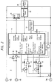
FIG. 1 ,reference numeral 1 denotes a charging device housed in an electronic device such as a video tape recorder having a built-in camera (hereinafter referred to as a video camera) or the like. Also, inFIG. 1 ,reference numeral 2 denotes anAC adapter 2 connected to a commercially-available power supply to supply the power to the video camera and thecharging device 1. - This
charging device 1 includes acharging circuit 3, acalculation processing microcomputer 5 and adisplay device 6 and thischarging circuit 3 charges a battery cell 20 (seeFIG. 2 ) of abattery pack 4 that is used to drive the video camera when a user carries the video camera. Thecharging circuit 3 is arranged as is well known in the prior art. Thisbattery pack 4 includes at least a battery calculation processing means 4a for obtaining battery cell voltage detection information and charging current cumulated amount information a communication processing means 4b for communicating each of the information. - An example of this
battery pack 4 is shown inFIG. 2 . Referring toFIG. 2 , a positive electrode of thebattery cell 20 of thebattery pack 4 is connected to a plus terminal TM1 of thisbattery pack 4, and a negative electrode of thebattery cell 20 is connected through a current detection resistor R7 to a minus terminal TM2 of thisbattery pack 4. The plus terminal TM1 and the minus terminal TM2 are respectively connected to a plus terminal and a minus terminal at the output side of thecharging circuit 3 of thecharging device 1. - The power from a
microcomputer power supply 16 including a series regulator, a reset circuit or the like is supplied to amicrocomputer 10 housed in thebattery pack 4. Themicrocomputer 10 is operated by the power supplied from thismicrocomputer power supply 16. By the way, themicrocomputer 10 has functions of the battery calculation processing means 4a and communication processing means 4b. A charging current detection input terminal D11 of thismicrocomputer 10 is connected to an output terminal of anoperational amplifier 13 provided to detect a charging current. A discharging current detection input terminal D12 thereof is connected to an output terminal of anoperational amplifier 14 provided to detect a discharging current. Both theoperational amplifiers - An interrupt input terminal of the
microcomputer 10 is connected to an output terminal of a 2-input NAND gate 15 having two input terminals connected to the respective output terminals of theoperational amplifiers input NAND gate 15 is connected through a pull-up resistor R8, for example, to a power supply terminal. Also, a temperature detection input terminal of themicrocomputer 10 is connected to an output terminal of atemperature sensor 19 which detects an ambient temperature of thebattery cell 20. A voltage detection input terminal thereof is connected to an output terminal of avoltage detection circuit 18 which is used to detect a terminal voltage of thebattery cell 20. A ground terminal GND thereof is connected to the negative electrode of thebattery cell 20. An output and input terminal TMC used to communicate with thecalculation processing microcomputer 5, which comprises a computation means of thecharging device 1 of the video camera as will be described later on, is connected tobuffer amplifiers - Incidentally, analog input terminals such as the charging current detection input terminal D11, the discharging current detection input terminal D12, the temperature detection input terminal, the voltage detection input terminal and so on are all A/D input ports. Therefore, the
microcomputer 10 houses an A/D converter for converting these analog input into digital form. - The
voltage detection circuit 18 is formed of a voltage-dividing resistor comprising resistors R9 and R10. A voltage across thebattery cell 20 is detected by this voltage-dividing resistor. A voltage detection value from thisvoltage detection circuit 18 is supplied to the voltage detection input terminal of themicrocomputer 10. Accordingly, themicrocomputer 10 is able to learn the terminal voltage across thebattery cell 20 based on the voltage detection value supplied to this voltage detection input terminal from thevoltage detection circuit 18. - Also, the
temperature sensor 19 is comprised of a suitable device such as a temperature detection thermistor or the like. Thetemperature sensor 19 is disposed in the vicinity of or in contact with thebattery cell 20, and a temperature detection value of thistemperature sensor 19 is supplied to the temperature detection input terminal of themicrocomputer 10. Accordingly, themicrocomputer 10 is able to learn a temperature of thebattery cell 20 based on the temperature detection value supplied to this temperature detection input terminal. - Then, a non-inverting input terminal of the
operational amplifier 13 is connected through a resistor R3 to the negative electrode of thebattery cell 20, and an inverting input terminal thereof is connected through a current voltage detection resister R7 to the negative electrode of thebattery cell 20 and also to an amplification factor setting negative feedback resistor R2 and a resistor R1. Accordingly, theoperational amplifier 13 outputs from its output terminal a voltage value which results from amplifying a current value (current value flowing upon charging) flowing into thebattery pack 4 in response to a ratio (R2/R1) of resistance values of the resistors R1 and R2. - On the other hand, a non-inverting input terminal of the
operational amplifier 14 is connected through a resistor R6 and the current voltage detection resistor R7 to the negative electrode of thebattery cell 20. An inverting input terminal thereof is connected to a negative feedback resistor R5 and a resistor R4. Accordingly, theoperational amplifier 14 outputs from its output terminal a voltage value which results from amplifying a current value (current value flowing upon discharging) flowing into thebattery pack 4 in response to a ratio (R5/R4) of resistance values of the resistors R4 and R5. - A transistor switch Tr1 is comprised of a field-effect transistor, for example, and whose gate is connected to a switching control output terminal SW1 of the
microcomputer 10. The resistor R1 is connected between the drain and the source of this transistor switch Tr1. Accordingly, when the level of the signal from the switching control output terminal SW1 of themicrocomputer 10 goes to a high (H) level, for example, the transistor switch Tr1 is turned ON, whereby the resistance value based on this resistor R1 becomes approximately 0 (there is only the internal resistor of the transistor switch Tr1), thereby resulting in the amplification factor (amplifier gain) of theoperational amplifier 13 whose amplification factor is set in response to the ratio (R2/R1) of the resistance values of the resistors R1 and R2 being increased. - On the other hand, when the level of the signal from the switching control output terminal SW1 of the
microcomputer 10 goes to a low (L) level, for example, the transistor switch Tr1 is turned OFF, whereby the amplification factor of thisoperational amplifier 13 becomes such one corresponding to the ratio (R2/R1) of the resistance values of the resistors R1 and R2, i.e. amplification factor (amplifier gain) smaller than that obtained when the transistor switch Tr1 is placed in the ON state. Similarly, a transistor switch Tr2 is comprised of a field-effect transistor, for example, and whose gate is connected to a switching control output terminal SW2 of themicrocomputer 10. The resistor R4 is connected between the drain and the source of the transistor switch Tr2. - Accordingly, when the level of the signal from the switching control output terminal SW2 of the
microcomputer 10 goes to a high (H) level, for example, the transistor switch Tr2 is turned ON, thereby resulting in a resistance value of the resistor R4 being decreased to approximately 0 (there is only the internal resistance of the transistor switch Tr2). Thus, the amplification factor (amplifier gain)of theoperational amplifier 14 increases. On the other hand, when the level of the signal from the switching control output terminal SW2 of themicrocomputer 10 goes to a low (L) level, for example, the transistor switch Tr2 is turned OFF, thereby resulting in the amplification factor (amplifier gain)of theoperational amplifier 14 being decreased. - The
microcomputer 10 constantly monitors the levels of the charging current detection input terminal D11 and the discharging current detection input terminal D12 in the normal operation mode (Run mode). When the levels of these terminals D11, D12 are higher than the constant level, themicrocomputer 10 causes the signal levels of the switching control output terminals SW1 and SW2 to be held at low level. Thus, the transistor switches Tr1 and Tr2 are both turned OFF, thereby resulting in the amplifier gains of theoperational amplifiers microcomputer 10 in the normal operation mode (Run mode) becomes able to measure a current value (current value flowing in the charging or current value flowing in the discharging) flowing into thebattery pack 4 by using the output values obtained from theoperational amplifiers - Also, in the above-mentioned example, data of a battery cell voltage V, a charging current I, a charging current cumulated amount Q and temperature dependence coefficients h1(T) and h2(T) from the
battery pack 4 are supplied to thecalculation processing microcomputer 5 comprising the computing means of thischarging device 1. - Also, data of a power consumption W of a video camera using this
battery pack 4 is supplied to thiscalculation processing microcomputer 5. - This
calculation processing microcomputer 5 is operated in accordance with a flowchart shown inFIG. 4 . Thiscalculation processing microcomputer 5 computes the charging capacity of thebattery cell 20 of the chargedbattery pack 4 being charged and displays a computed charging capacity on thedisplay device 6 which will be described later on. At that same time, thiscalculation processing microcomputer 5 computes a time during which the present charging capacity can run the video camera using thisbattery pack 4, and displays this computed time on thedisplay device 6. - This
display device 6 includes a presentcharging capacity indicator 30 comprising 5-step indicators a, b, c, d, e as shown inFIG. 3 . The uppermost portion in the indicator upon charging is blinked. When the charging capacity ranges from 0 to 20%, for example, the indicator a is blinked; when the charging capacity ranges from 20 to 40%, the indicator a is lit and at the same time, the indicator b is blinked; when the charging capacity ranges from 40 to 60%, the indicators a and b are lit and at the same time, the indicator c is blinked; when the charging capacity ranges from 60 to 80%, the indicators a, b, c are lit and at the same time, the indicator d is blinked; when the charging capacity ranges from 80 to 100%, the indicators a, b, c, d are lit and at the same time, the indicator e is blinked; and when the charging capacity is greater than 100%, the indicators a, b, c, d, e are all lit. - Also, in the present charging capacity of the
display device 6, as a runningpossible time indicator 31 of a video camera using thisbattery pack 4 that is being charged, there may be used numerals, e.g. time indication such as 229min shown inFIG. 3 . - An example of the manner in which the
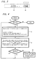
battery cell 20 of thebattery pack 4 is charged by the chargingdevice 1 according to the above-mentioned example will be described next with reference to a flowchart ofFIG. 4 . - Initially, the charging
device 1 of the video camera is powered by theAC adapter 2, and thebattery pack 4 which will be charged is attached to the video camera at its predetermined position. At that time, it is determined by thecalculation processing microcomputer 5 whether or not the attached battery pack is a battery pack that can be charged (step S1). If the battery pack is a battery pack such as a dry cell or the like that cannot be charged, then the charging is ended. - If the attached
battery pack 4 is the battery pack that can be charged, then the charging current is supplied from the chargingcircuit 3 of thecharging device 1 to thebattery cell 20 of thebattery pack 4, and control goes to a step S2. In this step S2, thecalculation processing microcomputer 5 in thecharging device 1 receives data of a battery cell voltage V, data of a charging current I, data of a charging current cumulated amount Q and data of temperature dependence coefficients h1(T), h2(T) transmitted from thebattery pack 4. Data of video camera power consumption data W also is stored in a memory provided in thiscalculation processing microcomputer 5. - Then, control goes to a step S3, and in this step S3, there are computed a charging capacity and a shooting possible time based on a present charging capacity.
- This charging capacity can be obtained by a ratio of a charging current cumulated remaining amount S, obtained by the following equation, and a whole capacity of the
battery cell 20. Incidentally, the whole capacity and temperature dependence coefficients h1(T), h2(T) are transmitted from thebattery pack 4 through its communication processing means 4b. - Charging current cumulated remaining amount

where g(W) is the discharge cumulated amount cumulated from the video camera running possible minimum voltage to the full discharge of thebattery cell 20 and depends upon the power consumption W. - In this case, when the temperature dependence is not taken into consideration, this charging current cumulated remaining amount S is expressed as:


- A video camera running possible time based on the present charging capacity of the battery cell during the charging can be obtained by multiplying the charging current cumulated remaining amount S with f(W) and the temperature coefficient h1(T) as expressed by the following equation. That is, the video camera running possible time R = S x f(W) x h(T) where f(W) is the coefficient for converting the charging current cumulated amount Q into the video camera running possible time and which depends upon the power consumption W of this video camera.
- In this case, if the temperature dependence is not taken into consideration, this video camera running possible time R is expressed as:

- Then, it is determined whether or not the charging capacity and the video camera running possible time thus calculated can be indicated (step S4). If they can be indicated, then the charging capacity and the video camera running possible time are displayed on the
display device 6 of thecharging device 1 as theindicators - According to the above-mentioned example, since the present charging capacity of the
battery cell 20 being charged is calculated by thecalculation processing microcomputer 5 of thecharging device 1 and indicated on thedisplay device 6 and the video camera running possible time of the video camera using thisbattery pack 4 is calculated based on the present charging capacity and indicated on thedisplay device 6, the present charging capacity of thebattery cell 20 being charged may be learned with ease, and the video camera running possible time of the video camera using thebattery pack 4 may be learned with ease, thereby making the battery system become more convenient for the user. - However, in the above-mentioned charging device, when this charging device is formed independently of the electronic device such as the video camera or the like, it is necessary for the charging device to learn the power consumption of the electronic device that is driven by the
battery pack 4. In order for the charging device to learn the power consumption of this electronic device, heretofore, there may be considered a method in which a signal line is used to connect this charging device and the electronic device to thereby input the power consumption of this electronic device into the charging device. - On the other hand, in the case of the electronic device such as the video camera or the like, in most cases or the like, the battery pack (discharging state) 4 which drives this electronic device and the charging device which charges this
battery pack 4 are formed in many case independently of each other in order to maintain a safety or the like. - If this electronic device and the charging device are integrally formed as one body as seen in the above-mentioned example, then this charging device is difficult to have a highly value-added function such as boosting charge and custom charge for individual battery pack because a cost of a product increases and a space for mounting such charging device is limited.
- Under such situation, if the electronic device and the charging device are made separately and the charging device is formed independently in general, there are following requirements:
- (1) To indicate a running possible time of an electronic device to which the battery pack is attach when the battery cell of the battery pack is charged by the charging device. Further, to correct an error of the electronic device running possible time indication in response to a future change of a power consumption of an electronic device driven by this battery pack.
- (2) To correct an error of a running possible time indication during an electronic device is in use by the electronic device driven to which this battery pack is attached after the electronic device has understood the degree in which the performance of the battery pack is lowered upon charging by the single charging device.
- (3) To correct an amount of a dark current flowing in the battery cell within the battery pack by the charging device or the electronic device driven by the battery pack during a time period from the end of the charging to the start of the discharging, from the end of the discharging to the start of the charging or the like.
- When the charging device or the electronic device to which the battery pack is attached and driver thereby intends to meet with the above-mentioned requirements under the condition that the charging device and the electronic device are formed separately, the charging device needs to learn the situation (information) caused in the electronic device and the electronic device needs to learn the situation (information) caused in the charging device.
- According to one aspect of the present invention, there is provided battery pack comprising: a battery; a memory means for storing predetermined data including data (DB) relating to the life of the battery; a processing means arranged to produce battery data relating to at least the state of charge of the battery and for controlling the writing of said predetermined data into the memory means and the reading of stored predetermined data from the memory means; and a communications interface wherein the interface, processing means and memory means are arranged to both a) transfer battery data from the processing means and the predetermined data from the memory means via the interface is to an electronic device which in use is energised by the battery or (ii) to a charging device for charging the battery; and b) transfer predetermined data including data (DB) relating to the life of the battery via the interface from the electronic device or charging device to the memory means.
- According to another aspect of the present invention, there is provided an electronic device which, in use, is energisable by the battery of the battery pack, of the device comprising a communication interface for communication with the interface of the battery pack; memory means for storing predetermined data including data (DB) relating to the life of the battery; and processing means arranged to produce further data for display and for controlling the writing of the predetermined data into the memory means and the reading of stored predetermined data including data (DB) relating to the life of the battery from the memory means; wherein the interface, memory means and processing means are arranged to both a) transfer at least predetermined data including data (DB) relating to the life of the battery from the processing means and/or memory means of the electronic device via the interface to the battery pack; and b) transfer predetermined data including data (DB) relating to the life of the battery and battery data produced by the processing means of the battery pack via the interface from the battery pack to the memory means of the electronic device, the said further data produced by the processing means including the running possible time of the battery, and being dependent on the said predetermined data and the said battery data.
- According to a further aspect of the present invention, there is provided a charging device for charging the battery of the battery pack, the charger comprising: a charging circuit for providing charging current to the battery pack; a communication interface for communication with the interface of the battery pack; memory means for storing predetermined data including data (DB) relating to the life of the battery; and processing means arranged to produce further data for display and for controlling the writing of the predetermined data into the memory means and the reading of stored predetermined data from the memory means; wherein the interface, memory means and processing means are arranged to both a) transfer at least predetermined data including data (DB) relating to the life of the battery from the memory means and/or processing means of the charger via the interface to the battery pack and b) transfer predetermined data including data (DB) relating to the life of the battery and battery data produced by the processing means of the battery base from the battery pack via the interface to the memory means of the charger the said further data produced by the processing means of the charging device including the running possible time of the battery and being dependent on the said predetermined data and the battery data produced by the processing means of the battery pack.
- Thus, in embodiments of the present invention, data is exchanged between the charger and the electronic device via a memory means in the battery pack without the need for a supplementary communication link between the charger and electronic device.
- For a better understanding of the present invention reference will now be made, by way of example, to the accompanying drawings in which:
-
FIG. 1 is a block diagram showing an example of a battery system; -
FIG. 2 is a block diagram showing an example of a battery pack; -
FIG. 3 is a diagram showing an example of a display; -
FIG. 4 is a flowchart used to explainFIG. 1 ; -
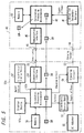
FIG. 5 is a block diagram showing a battery system according to an embodiment of the present invention; -
FIG. 6 is a block diagram showing a battery system according to other embodiment of the present invention; -
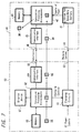
FIG. 7 is a block diagram showing a battery system according to other embodiment of the present invention; -
FIG. 8 is a block diagram showing a battery system according to other embodiment of the present invention; -
FIG. 9 is a block diagram showing a battery system according to other embodiment of the present invention; and -
FIG. 10 is a block diagram showing a battery system according to other embodiment of the present invention. - A battery pack and a battery system according to an embodiment of the present invention will hereinafter be described with reference to
FIGS. 5 to 10 . - In
FIGS. 5 to 10 ,reference numeral 40 designates a battery pack according to this embodiment. Thisbattery pack 40 comprises: abattery cell 41 formed of a lithium ion secondary battery for example; amicrocomputer 42 for executing a calculation processing or the like to obtain a voltage of thisbattery cell 41, its charging and discharging currents and a cumulated amount of currents based on charging and discharging; and amemory 43 in which predetermined information is written or from which predetermined information is read out in accordance with a command from themicrocomputer 42. - In this
battery pack 40, a charging and discharging terminal of thebattery cell 41 is connected to a charging and dischargingterminal 44 of thisbattery pack 40, and an output and input terminal of themicrocomputer 42 is connected through acommunication interface 45 to acommunication terminal 46 of thisbattery pack 40. - In
FIGS. 8 and9 ,reference numeral 50 designates an electronic device such as a video camera or the like. In thiselectronic device 50, anelectronic device body 51 is controlled by amicrocomputer 52 which executes a calculation processing or the like. A power supply terminal of thiselectronic device body 51 is connected to apower supply terminal 53 of theelectronic device 50 and an output and input terminal of thismicrocomputer 52 is connected through acommunication interface 54 to acommunication terminal 55 of theelectronic device 50. - Also, this
electronic device 50 includes amemory 56 in which predetermined information is written or from which predetermined information is read out in accordance with a command from themicrocomputer 52 and a liquid-crystal display device 57 for displaying a video picture (shot picture), for example, in accordance with a command from themicrocomputer 52. Further, thiselectronic device 50 includes adisplay device 58 for displaying a variety of controlled states in accordance with a command from themicrocomputer 52. - In
FIGS. 6 ,7 and10 ,reference numeral 60 denotes a charging device. This chargingdevice 60 includes a chargingcircuit 61. This chargingcircuit 61 is supplied with a commercially-available power, and this chargingcircuit 61 is charged under control of amicrocomputer 62 which executes a calculation processing or the like. A charging current obtained at the output terminal of this chargingcircuit 61 is supplied to a chargingterminal 63 of this chargingdevice 60. - An output and input terminal of this
microcomputer 62 is connected through acommunication interface 64 to acommunication terminal 65 of the chargingdevice 60. This chargingdevice 60 includes amemory 66 in which predetermined information is written or from which predetermined information is read out in accordance with a command from themicrocomputer 62. - Also, this charging
device 60 includes adisplay device 67 shown inFIG. 3 for displaying the charged capacity of thebattery cell 41 of thebattery pack 40 in the charging in accordance with a command from themicrocomputer 62 which executes a calculation processing or the like. Thisdisplay device 67 is also able to display a time during which theelectronic device 50 such as the video camera or the like using thisbattery pack 40 can be used by the present charged capacity. - Further, in
FIG. 5 ,reference numeral 50a denotes an apparatus in which the charging device is assembled into the electronic device such as the video camera or the like similarly to the example shown inFIG. 1 . In theapparatus 50a in which the charging device is assembled into this electronic device, a power from anAC adapter 59, which generates a predetermined DC voltage in response to a commercially-available power, is supplied to theelectronic device body 51 and the chargingcircuit 61. A charging current developed at the output side of this chargingcircuit 61 is supplied to the chargingterminal 63. - Also, this
apparatus 50a includes amicrocomputer 52a having a function with functions of themicrocomputers microcomputer 52a controls theelectronic device body 51 and the chargingcircuit 61. - Also, this
apparatus 50a includes adisplay device 67a.
Thisdisplay device 67a displays, in accordance with a command from themicrocomputer 52a, the charged capacity of thebattery cell 41 of thebattery pack 40 in the charging and a time in which the electronic device such as the video camera or the like using thisbattery pack 40 can be used by the present charged capacity as shown inFIG. 3 , for example. A rest of arrangement is made similar to that of the electronic device shown inFIGS. 8 and9 . - An operation of the battery system according to this embodiment will be described next.
- Initially, the manner of displaying a time during which the
electronic device body 51 can be driven by the chargedbattery pack 40 after thebattery cell 41 of thebattery pack 40 was charged by theapparatus 50a in which the charging device is assembled into the electronic device such as the video camera or the like will be described with reference toFIG. 5 . - At that time, as shown in
FIG. 5 , thecommunication terminal 55 of theapparatus 50a and thecommunication terminal 46 of thebattery pack 40 are connected together thereby to communicate with each other via data. At the same time, the chargingterminal 63 of thisapparatus 50a is connected to the charging and dischargingterminal 44 of thebattery pack 40, and the charging current from the chargingcircuit 61 is supplied to thebattery cell 41 of thebattery pack 40, thereby resulting in thisbattery cell 41 being charged. - In this case, data of a battery voltage V of the
battery cell 41, a charging current I, a charging current cumulated value Q and temperature dependence coefficients h1(T), h2(T) are transmitted from thebattery pack 40 to thisapparatus 50a via communication. Themicrocomputer 52a of thisapparatus 50a calculates the running possible time of thiselectronic device body 51 from these data values in accordance with the following equations: - Charging current cumulated remaining amount


- If the power consumption W of this
electronic device body 51 is stored in thememory 56 or this power consumption is calculated by themicrocomputer 52a, then it is possible to calculate a time period during which theelectronic device body 51 can be driven by thebattery cell 41 of thebattery pack 40 in charging. The time thus calculated is supplied to thedisplay device 67a, and thedisplay device 67a displays this running possible time. - When the charging
device 60 is formed independently of theelectronic device 50 such as the video camera or the like as shown inFIG. 6 , in this case, the chargingdevice 60 is provided as the single unit and is therefore unable to learn the power consumption W of thiselectronic device 50. - Accordingly, as shown in
FIG. 5 when thebattery pack 40 is connected to theapparatus 50a, thisapparatus 50a transmits data DW of the power consumption W of theelectronic device body 51 to thebattery pack 40 via communication, and thebattery pack 40 stores the transmitted data DW of the power consumption W of theelectronic device body 51 in thememory 43 of thisbattery pack 40. - The manner of displaying a time period during which the
electronic device 50 can be driven by thebattery cell 41 of thebattery pack 40 which is being charged by theindependent charging device 60 will be described next with reference toFIG. 6 . At that time, as shown inFIG. 6 , thecommunication terminal 65 of the chargingdevice 60 and thecommunication terminal 46 of thebattery pack 40 are connected together thereby to effect a data communication. At the same time, the chargingterminal 63 of this chargingapparatus 60 is connected to the charging and dischargingterminal 44 of thebattery pack 40 to thereby supply the charging current from the chargingcircuit 61 to thebattery cell 41 of thebattery pack 40. Thus, thebattery cell 41 is charged. - In this case, the data DW of the power consumption W of the
electronic device 50 stored (memorized) in thememory 43 of thebattery pack 40 is transmitted to the chargingdevice 60 via communication, and this data DW is memorized in thememory 66. Themicrocomputer 62 in the chargingdevice 60 uses the data DW of the power consumption W of theelectronic device 50 stored in thismemory 66 to calculate the time period during which the electronic device using thebattery pack 40 that is being charged can be driven according to the above equation. The calculated result is displayed on thedisplay device 67. - That is, in this case, the
microcomputer 62 of the chargingdevice 60 is able to obtain the data DW of the power consumption W of theelectronic device 50 necessary for the calculation processing from thememory 43 of thebattery pack 40 that is to be charged and hence, a signal line is not required between theelectronic device 50 and the chargingdevice 60. - If the power consumption W of the
electronic device 50 is constantly made constant, then the coefficient f(W) dependent upon the power consumption W is constant. However, if this power consumption W is changed, then this coefficient f(W) also is changed. For example, this coefficient is changed not only when the liquid-crystal display device 57 for displaying a video picture is turned on/off but also when the kind and the type of the electronic device such as the video camera or the like are changed. - It is impossible for the charging
device 60 to cope with a future change of such coefficient f(W) (coefficient f(W) contains end voltage correction values separately set in thebattery cell 41 in response to the increase and decrease of the power consumption of the electronic device such as the video camera or the like). That is, if only one kind of this coefficient f(W) had been stored (memorized) in the chargingdevice 60, the charging device would not cope with the future change of the power consumption of thiselectronic device 50. As a result, there occurs an error in the display of this running possible time. - Accordingly, in this embodiment, each time the
apparatus 50a is connected to thebattery pack 40 as shown inFIG. 5 , for example, data of the coefficient f(W) corresponding to the change of the power consumption W as well as the data DW of the changed power consumption W of theelectronic device body 51 of thisapparatus 50a are transmitted to thememory 43 of thebattery pack 40 and thereby memorized (stored) therein. - Thus, since the charging
device 60 may use the coefficient f(W) stored in thebattery pack 40 also and may cope with the future change of the electronic device, it may reduce the occurrence of the error in the display of the running possible time. - In this case, the data DW of the power consumption W and the data of the coefficient f(W) stored (memorized) in the
memory 43 of thebattery pack 40 may be updated not only once but also a plurality of times and stored (memorized) when thebattery pack 40 is connected to the device. - Also, it is generally known that the charging and discharging capacity of the
battery cell 41 of thebattery pack 40 is lowered in performance by the number of charging and discharging in thebattery cell 41, years in which the battery cell has been in use, a temperature of a circumstance in which the battery cell is in use or the like (battery life). - Initially, a method of confirming a battery life upon charging will be described. As a method of confirming the life of the
battery cell 41 of thebattery pack 40, it is possible to confirm the life of the battery cell by comparing a charging current cumulated value Q obtained after a certain charging time elapsed and an initial value (charging current cumulated value that should be originally set after a certain charging time elapsed). - That is, if the charging current cumulated value Q is lower than the initial value, then this means that the charging and discharging capacity of the
battery cell 41 is lowered. Accordingly, assuming that Qc is a value which results from subtracting the charging current cumulated value Q from the initial value, then the life of thebattery cell 41 may be confirmed by the following equation:
- According to this embodiment, as shown in
FIG. 7 , when thebattery cell 41 of thebattery pack 40 is charged by the chargingdevice 60, data DB of this battery life level value B is transmitted to thebattery pack 40 via communication, and stored (written) in thememory 43 of thisbattery pack 40. - In this case, when the
battery cell 41 of thebattery pack 40 is charged by the chargingdevice 60, as shown inFIG. 7 , the chargingterminal 63 of the chargingdevice 60 is connected to the charging and dischargingterminal 44 of thebattery pack 40 and thecommunication terminal 65 of the chargingdevice 60 and thecommunication terminal 46 of thebattery pack 40 are connected with each other. - Also, when the
electronic device 50 is driven by thisbattery pack 40, as shown inFIG. 8 , theelectronic device 50 reads out the data DB of the battery life level B from thememory 43 of thebattery pack 40 and receives the same via communication. That is, theelectronic device 50 is able to learn the battery life level value B through thememory 43 of thisbattery pack 40 without being connected to the chargingdevice 60 via the signal line. - In this case, when the
electronic device 50 is driven by thebattery pack 40, the charging and dischargingterminal 44 of thebattery pack 40 is connected to thepower supply terminal 53 of theelectronic device 50 and, at the same time, thecommunication terminal 55 of theelectronic device 50 and thecommunication terminal 46 of thebattery pack 40 are connected with each other. - A method of confirming the battery life by the
electronic device 50 will be described next. - When the
battery pack 40 is connected to theelectronic device 50 in use as shown inFIG. 9 (FIG. 8 ), the charging current cumulated value (discharging current cumulated value) Q decreases in response to the discharging current, thereby making the discharging become possible until the charging current cumulated value Q reaches 0. - However, it is frequently observed that, as the performance of the
battery cell 41 is lowered, the battery cell voltage V reaches the battery end voltage of theelectronic device 50 before the charging current cumulated value Q reaches 0, thereby resulting in theelectronic device 50 being stopped in use. - Accordingly, assuming that QD is a remaining amount of the charging current cumulated amount Q at the battery end voltage, then the battery life level value B may be confirmed by the above-mentioned equation:

- According to this embodiment, as shown in
FIG. 9 , when theelectronic device 50 is driven by thebattery pack 40, the data DB of this battery life level value B is transmitted to thebattery pack 40 via communication, and thereby stored in thememory 43 of thisbattery pack 40. - Next, as shown in
Fig. 10 (FIG. 7 ), when thebattery cell 41 of thebattery pack 40 is charged by the chargingdevice 60, the data DB of the battery life level value B stored in thememory 43 of thisbattery pack 40 is read out and received via communication. That is, the chargingdevice 60 is able to learn the battery life level value B through thememory 43 of thisbattery pack 40 without being connected to theelectronic device 50 by the signal line. - As described above, when the charging corresponding to the battery life level value B, e.g. the performance of the
battery cell 41 of thebattery pack 40 is lowered, the chargingdevice 60 intends to extend the life of thebattery cell 41 by decreasing the charging current. - In this case, the data DB of the battery life level value B stored in the
memory 43 of thebattery pack 40 may be updated each time the battery cell is charged. - While the battery life level value B is used when the battery cell is charged and is used in the
electronic device 50 as described above, battery life level values may be independently calculated when the battery cell is charged and is used in theelectronic device 50. It is possible to calculate a more accurate value by a proper method such as comparing battery life level values obtained when the battery cell is charged and is used in theelectronic device 50. - In general, the discharging and the charging are not always started immediately after the charging of the
battery cell 41 of thebattery pack 40 was finished or immediately after the driving of theelectronic device 50 using thebattery pack 40 was ended. When the charging and the discharging are not respectively started immediately after the charging of the battery cell of the battery pack was finished or immediately after the driving of the electronic device using the battery pack was ended, the discharging of thebattery cell 41 of thebattery pack 40 is caused to progressing by a dark current produced within thisbattery cell 41 and a consumed current (hereinafter referred to as a dark current) of a battery protecting circuit, thereby the charging and discharging capacity of thebattery cell 41 being lowered. - Since a value of this dark current is as very small as several microamperes to several 10s of microamperes, it is very difficult to detect this dark current.
- However, in order that a running possible time of the
battery pack 40 relative to thiselectronic device 50 may be displayed correctly during theelectronic device 50 is in use, it is necessary to consider (correct) an influence by this dark current. - Accordingly, in this embodiment, if the battery system is connected as shown in
FIG. 7 and thebattery cell 41 of thebattery pack 40 is charged by the chargingdevice 60, then when the charging is ended, data indicative of the time and date in which the charging is ended is transmitted to thebattery pack 40 via communication, and the data indicative of such time and date is stored (memorized) in thememory 43 of thebattery pack 40. - The
electronic device 50 receives the data indicative of the time and date of the end of the charging stored in thememory 43 of thisbattery pack 40 via communication when thebattery pack 40 is connected thereto as shown inFIG. 8 , compares the received data of such time and date with the present time and date and calculates a dark current equivalent to a difference of such time and date, thereby making it possible, during using theelectronic device 50, to correct an error in displaying a running possible time of thebattery pack 40 relative to thiselectronic device 50. - Alternatively, as shown in
FIG. 9 , when the use of thebattery pack 40 in theelectronic device 50 is ended, data indicative of time and date in which the use of the battery pack is ended is transmitted to thebattery pack 40 via communication and stored (memorized) in thememory 43 of thebattery pack 40. Then, when thebattery cell 41 of thisbattery pack 40 is charged by the chargingdevice 60 as shown inFIG. 10 , the charging device receives the data indicative of the time and date in which the use of thisbattery pack 40 is ended stored (memorized) in thememory 43 of thisbattery pack 40 via communication, compares the received data of such time and date with the present time and date and calculates a dark current equivalent to a difference of such time and date. Thus, the charging device is able to judge whether or not thebattery cell 41 of thebattery pack 40 is discharged excessively or to judge the progressing level of the excessive discharging. Therefore, the chargingdevice 60 may charge thebattery cell 41 in response to the progressing level of the excessive discharging. - In this case, because the
electronic device 50 is driven by using thebattery pack 40 over and over, data indicative of time and date stored in thememory 43 of thebattery pack 40 should preferably be updated each time the electronic device is used. - As described above, in this embodiment, without connecting the charging
device 60 and theelectronic device 50 by a signal line, the chargingdevice 60 and theelectronic device 50 may store, share and exchange information (data) via thememory 43 of thebattery pack 40. There is then the benefit that the battery system may have a high value-added function without deteriorating the convenience and portability of the chargingdevice 60 and theelectronic device 50. - For example, during the
battery cell 41 of thebattery pack 40 is being charged, the battery system may cope with a future change of a power consumption of theelectronic device 50 while reducing the error in displaying the running possible time of the battery cell in theelectronic device 50. Therefore, when a new type of theelectronic device 50, for example, is put on sale, it is not necessary for the user to purchase a newcorresponding charging device 60. - Also, since it becomes possible to set a charging load and a discharging load in accordance with the life level of the
battery cell 41 of thebattery pack 40, the life of thebattery cell 41 of thebattery pack 40 may be extended more. When a lithium ion secondary battery, for example, is used as thisbattery cell 41, there is then the benefit that rare natural resources such as cobalt or the like may be saved. - Having described preferred embodiments of the present invention with reference to the accompanying drawings, it is to be understood that the present invention is not limited to the above-mentioned embodiments and that various changes and modifications can be effected therein by one skilled in the art without departing from the present invention.
Claims (23)
- A battery pack comprising:a battery (41);a memory means (43) for storing predetermined data including data (DB) relating to the life of the battery;a processing means (42) arranged to produce battery data relating to at least the state of charge of the battery (41) and for controlling the writing of said predetermined data into the memory means (43) and the reading of stored predetermined data from the memory means (43) ; anda communications interface (45) whereinthe interface (45), processing means (42) and memory means (43) are arranged to botha) transfer battery data from the processing means and the predetermined data from the memory means (43) via the interface (45) (i) to an electronic device (50) which in use is energised by the battery or (ii) to a charging device (60) for charging the battery; andb) transfer predetermined data including data (DB) relating to the life of the battery via the interface (45) from the electronic device or charging device to the memory means (43).
- A battery pack according to claim 1, wherein the processing means (42) is arranged to produce battery data relating to: battery voltage; battery discharge current or battery charging current; and accumulated charge.
- A battery pack according to claim 1 or 2, wherein the battery (41) is a lithium ion secondary battery.
- A battery pack according to claim 1, 2 or 3, wherein the memory means (43) of the battery pack stores, as predetermined data, data relating to battery power (DW, f(w)) consumed by the electronic device.
- A battery pack according to claim 1, 2, 3 or 4, wherein the memory means (43) stores, as predetermined data, data relating to time and date of the end of charging of the battery.
- A battery pack according to claim 1, 2, 3, 4 or 5, wherein the memory means (43) stores, as predetermined data, data relating to the time and date of the use of the battery pack in an electronic device.
- A battery pack according to claim 1, 2, 3, 4, 5 or 6, wherein the pack is arranged to transmit battery data (L(T)) relating to the temperature of the battery via the interface (45) to the charger or electronic device.
- An electronic device which, in use, is energisable by the battery of the battery pack according to any one of claims 1 to 7, the device comprising
a communication interface (54) for communication with the interface (45) of the battery pack;
memory means for storing predetermined data including data (DB) relating to the life of the battery (56); and
processing means (52, 52a) arranged to produce further data for display and for controlling the writing of the predetermined data into the memory means and the reading of stored predetermined data including data (DB) relating to the life of the battery from the memory means (56);
wherein the interface (54), memory means (56) and processing means (52, 52a) are arranged to botha) transfer at least predetermined data including data (DB) relating to the life of the battery from the processing means (52) and/or memory means (56) of the electronic device via the interface to the battery pack; andb) transfer predetermined data including data (DB) relating to the life of the battery and battery data produced by the processing means of the battery pack via the interface (54) from the battery pack to the memory means (56) of the electronic device,the said further data produced by the processing means including the running possible time of the battery and being dependent on the said predetermined data and the said battery data. - An electronic device according to claim 8, wherein the memory means (56) of the device stores, as predetermined data, data (DW) relating to the power consumption of the electronic device.
- An electronic device according to claim 8, wherein the processing means (52, 52a) of the device is arranged to produce, as predetermined data, data (DW) relating to the power consumption of the device and store such data in the memory means (56).
- An electronic device according to claim 8, 9 or 10, wherein the processing means (52, 52a) of the device is arranged to produce, as predetermined data, data relating to the time and date of use of the battery pack in the device and store such data in the memory means (43) of the battery pack via the interface (54).
- An electronic device according to any one of claims 8 to 11, further comprising display means (67, 67a) the processing means being arranged to calculate from the battery data received from the battery pack the stored predetermined data an indication of the running possible time of the battery and to cause the display means (58, 67a) to display an indication of the running possible time.
- An electronic device according to claim 12, wherein the processing means is arranged to calculate the running possible time as a function of:accumulated charge;battery temperature; andpower consumption.
- An electronic device according to claim 12, further comprising a charging circuit (61) for charging the battery pack;
wherein the processing means (52a) is arranged to cause the display means to display an indication of the state of charge of the battery. - An electronic device according to any one of claims 8 to 14, in combination with a battery pack according to any one of claims 1 to 7.
- A charging device for charging the battery of the battery pack according to any one of claims 1 to 8, the charger comprising:a charging circuit (61) for providing charging current to the battery pack (40);a communication interface (64) for communication with the interface (45) of the battery pack;memory means (66) for storing predetermined data including data (DB) relating to the life of the battery; andprocessing means (62) arranged to produce further data for display and for controlling the writing of the predetermined data into the memory means and the reading of stored predetermined data from the memory means (56);wherein the interface (64), memory means (66) and processing means (62) are arranged to botha) transfer at least predetermined data including data (DB) relating to the life of the battery from the memory means (66) and/or processing means of the charger via the interface to the battery pack andb) transfer predetermined data including data (DB) relating to the life of the battery and battery data produced by the processing means of the battery pack from the battery pack via the interface (64) to the memory means (66) of the chargerthe said further data produced by the processing means of the charging device including the running possible time of the battery and being dependent on the said predetermined data and the battery data produced by the processing means of the battery pack.
- A charging device according to claim 16, wherein the processing means (62) is arranged to produce, as predetermined data, data relating to the time and date of the end of charging of a battery pack by the charger and to store such data in the memory means (43) of the battery pack via the interface (64).
- A charging device according to claim 16 or 17 further comprising display means (67), the processing means (62) being operable to calculate from the predetermined data received from the battery pack and the battery data an indication of state of charge of the battery and to cause the display means (67, 67a) to display the said indication.
- A charging device according to claim 16, 17 or 18, wherein the processing means is arranged to calculate the said indication of the state of charge of the battery as a function of: accumulated charge; and battery temperature.
- A charging device according to claim 18 or 19, wherein the processing means (62) is operable to calculate the running possible time of an electronic device as a function of predetermined data (DW, f(w)) relating to the power consumption of the electronic device.
- A charging device according to any one of claims 16 to 20, wherein the processing means (62) is operable to receive, via the interface from the battery pack, predetermined data (DW) relating to power consumption of an electronic device and to store such data in the memory means (66) of the charger.
- A charging device according to any one of claims 16 to 20 in combination with a battery pack according to any one of claims 1 to 7.
- A system comprising a battery pack according to any one of claims 1 to 7, an electronic device according to any one of claims 8 to 15 and a charging device according to any one of claims 16 to 20, wherein at least the predetermined data is transferable from the charger to the electronic device and vice versa via the battery pack.
Priority Applications (1)
| Application Number | Priority Date | Filing Date | Title |
|---|---|---|---|
| EP06021638A EP1764895B1 (en) | 1998-02-13 | 1999-02-08 | Battery pack and battery system |
Applications Claiming Priority (3)
| Application Number | Priority Date | Filing Date | Title |
|---|---|---|---|
| JP3162198 | 1998-02-13 | ||
| JP03162198A JP4339423B2 (en) | 1998-02-13 | 1998-02-13 | Battery pack, battery system, and charging control method for battery system |
| JP2007079363A JP4683000B2 (en) | 1998-02-13 | 2007-03-26 | Charge control method for battery system |
Related Child Applications (1)
| Application Number | Title | Priority Date | Filing Date |
|---|---|---|---|
| EP06021638A Division EP1764895B1 (en) | 1998-02-13 | 1999-02-08 | Battery pack and battery system |
Publications (3)
| Publication Number | Publication Date |
|---|---|
| EP0936719A2 EP0936719A2 (en) | 1999-08-18 |
| EP0936719A3 EP0936719A3 (en) | 1999-12-08 |
| EP0936719B1 true EP0936719B1 (en) | 2008-11-05 |
Family
ID=54325264
Family Applications (2)
| Application Number | Title | Priority Date | Filing Date |
|---|---|---|---|
| EP06021638A Expired - Lifetime EP1764895B1 (en) | 1998-02-13 | 1999-02-08 | Battery pack and battery system |
| EP99300904A Expired - Lifetime EP0936719B1 (en) | 1998-02-13 | 1999-02-08 | Battery pack and battery system |
Family Applications Before (1)
| Application Number | Title | Priority Date | Filing Date |
|---|---|---|---|
| EP06021638A Expired - Lifetime EP1764895B1 (en) | 1998-02-13 | 1999-02-08 | Battery pack and battery system |
Country Status (7)
| Country | Link |
|---|---|
| US (1) | US6222348B1 (en) |
| EP (2) | EP1764895B1 (en) |
| JP (2) | JP4339423B2 (en) |
| CN (1) | CN1178327C (en) |
| CA (1) | CA2261414C (en) |
| DE (2) | DE69939848D1 (en) |
| TW (1) | TW415121B (en) |
Families Citing this family (34)
| Publication number | Priority date | Publication date | Assignee | Title |
|---|---|---|---|---|
| JP2001196098A (en) * | 2000-01-12 | 2001-07-19 | Matsushita Electric Ind Co Ltd | General battery pack |
| JP4423764B2 (en) * | 2000-07-25 | 2010-03-03 | 株式会社ニコン | Electronic camera |
| JP3674908B2 (en) * | 2000-09-21 | 2005-07-27 | Necトーキン栃木株式会社 | Battery pack |
| JP4691796B2 (en) * | 2001-02-14 | 2011-06-01 | ソニー株式会社 | Charging / discharging device and method, power supply device and method, power supply system and method, program storage medium, and program |
| WO2002067347A1 (en) * | 2001-02-20 | 2002-08-29 | Matsushita Electric Industrial Co., Ltd. | Battery pack |
| CN1305168C (en) * | 2001-12-22 | 2007-03-14 | 中兴通讯股份有限公司 | Method for active discharge of chargeable cell and its system |
| JP2003264931A (en) | 2002-03-08 | 2003-09-19 | Seiko Epson Corp | Secondary battery protector |
| JP2003319563A (en) * | 2002-04-24 | 2003-11-07 | Sony Corp | Electronic device with remaining battery voltage information display function |
| US7508168B2 (en) * | 2002-05-16 | 2009-03-24 | Sony Corporation | Electronic apparatus with remaining battery power indicating function |
| US6957996B2 (en) * | 2002-09-30 | 2005-10-25 | Radioshack Corporation | Toy car kit |
| US6913507B2 (en) * | 2002-09-30 | 2005-07-05 | Radioshack Corporation | Assembly for retaining a toy |
| US6945840B2 (en) * | 2002-09-30 | 2005-09-20 | Radioshack Corporation | Wheel assembly for a toy |
| US7288917B2 (en) * | 2002-09-30 | 2007-10-30 | Radio Shack Corporation | Transmitter for radio-controlled toy |
| US20050062878A1 (en) | 2003-03-26 | 2005-03-24 | Nikon Corporation | Power system and camera |
| JP4207651B2 (en) | 2003-05-07 | 2009-01-14 | ソニー株式会社 | Charger |
| JP4269769B2 (en) * | 2003-05-07 | 2009-05-27 | ソニー株式会社 | Battery pack and electronic device |
| CA2539723A1 (en) * | 2003-09-22 | 2005-04-07 | Valence Technology, Inc. | Electrical systems, power supply apparatuses, and power supply operations methods |
| KR100696780B1 (en) * | 2004-11-29 | 2007-03-19 | 삼성에스디아이 주식회사 | Battery monitoring device and its method |
| JP2006164820A (en) * | 2004-12-09 | 2006-06-22 | Sony Corp | Battery pack and charger |
| KR100686794B1 (en) * | 2005-01-25 | 2007-02-23 | 삼성에스디아이 주식회사 | Battery monitoring system and its method |
| JP2006275929A (en) * | 2005-03-30 | 2006-10-12 | Fujitsu Ten Ltd | Component deterioration degree evaluating apparatus and component deterioration degree evaluating method |
| CN1940585B (en) * | 2005-09-28 | 2010-08-11 | 财团法人工业技术研究院 | Battery module managing device for master-slave radio data secrete discrimination and tracking , and its management |
| JP4976000B2 (en) * | 2005-11-01 | 2012-07-11 | パナソニック株式会社 | Battery pack |
| JP2007205977A (en) * | 2006-02-03 | 2007-08-16 | Toyota Motor Corp | Monitor for secondary battery |
| JP5335207B2 (en) * | 2007-07-05 | 2013-11-06 | キヤノン株式会社 | Electronics |
| US7830120B2 (en) * | 2007-09-18 | 2010-11-09 | Nexergy, Inc. | Low side N-channel FET protection circuit |
| JP4816743B2 (en) | 2009-02-17 | 2011-11-16 | ソニー株式会社 | Battery pack and detection method |
| JP5524772B2 (en) * | 2010-09-02 | 2014-06-18 | 株式会社マキタ | Battery pack |
| TWI554887B (en) * | 2010-12-30 | 2016-10-21 | 群邁通訊股份有限公司 | System and method for charging an electronic device |
| US9599519B2 (en) * | 2012-03-07 | 2017-03-21 | Apple Inc. | Charging a battery based on stored battery characteristics |
| US9797784B2 (en) | 2012-03-07 | 2017-10-24 | Apple Inc. | Communication and monitoring of a battery via a single wire |
| JP5978730B2 (en) * | 2012-04-16 | 2016-08-24 | ソニー株式会社 | Information processing apparatus, information processing method, and program |
| JP6048448B2 (en) * | 2014-05-22 | 2016-12-21 | トヨタ自動車株式会社 | Method for determining reusable product application of used secondary battery and reconfiguring assembled battery reassembled product |
| US20230152388A1 (en) * | 2020-11-27 | 2023-05-18 | Lg Energy Solution, Ltd. | Battery Diagnosis Apparatus, Battery Diagnosis Method, Battery Pack, and Vehicle |
Family Cites Families (13)
| Publication number | Priority date | Publication date | Assignee | Title |
|---|---|---|---|---|
| US5164761A (en) * | 1991-03-06 | 1992-11-17 | Nikon Corporation | Battery system for camera |
| JPH04279876A (en) * | 1991-03-07 | 1992-10-05 | Nikon Corp | Secondary battery pack incorporating device of camera |
| US5629604A (en) | 1992-11-13 | 1997-05-13 | Zenith Data Systems Corporation | Computer power supply system |
| US5315287A (en) | 1993-01-13 | 1994-05-24 | David Sol | Energy monitoring system for recreational vehicles and marine vessels |
| EP0628833B1 (en) | 1993-06-08 | 2000-03-08 | Honda Giken Kogyo Kabushiki Kaisha | System for monitoring residual capacity of battery |
| US5606243A (en) | 1993-11-19 | 1997-02-25 | Nippon Soken, Inc. | Battery state judging apparatus |
| KR950025448A (en) | 1994-02-28 | 1995-09-15 | 김무 | Battery remaining capacity measuring device and measuring method |
| US5541489A (en) * | 1994-12-15 | 1996-07-30 | Intel Corporation | Smart battery power availability feature based on battery-specific characteristics |
| JPH08289407A (en) | 1995-02-13 | 1996-11-01 | Nippon Soken Inc | Power generation control device for hybrid vehicle |
| JPH0933623A (en) | 1995-07-19 | 1997-02-07 | Nissan Motor Co Ltd | Battery capacity meter |
| DE69505976T2 (en) * | 1995-09-27 | 2000-05-18 | Telital Spa | Electronic device with an intelligent battery |
| JP3941140B2 (en) * | 1996-03-08 | 2007-07-04 | ソニー株式会社 | Electronic device with battery usage remaining time display function and method of displaying remaining battery usage time |
| US6522361B2 (en) * | 1996-03-08 | 2003-02-18 | Sony Corporation | Electronic apparatus having the function of displaying the battery residual quantity and method for displaying the battery residual quantity |
-
1998
- 1998-02-13 JP JP03162198A patent/JP4339423B2/en not_active Expired - Fee Related
-
1999
- 1999-02-04 TW TW088101722A patent/TW415121B/en not_active IP Right Cessation
- 1999-02-08 EP EP06021638A patent/EP1764895B1/en not_active Expired - Lifetime
- 1999-02-08 DE DE69939848T patent/DE69939848D1/en not_active Expired - Lifetime
- 1999-02-08 EP EP99300904A patent/EP0936719B1/en not_active Expired - Lifetime
- 1999-02-08 CA CA2261414A patent/CA2261414C/en not_active Expired - Fee Related
- 1999-02-08 DE DE69941911T patent/DE69941911D1/en not_active Expired - Lifetime
- 1999-02-12 CN CNB991022041A patent/CN1178327C/en not_active Expired - Fee Related
-
2000
- 2000-02-16 US US09/504,442 patent/US6222348B1/en not_active Expired - Lifetime
-
2007
- 2007-03-26 JP JP2007079363A patent/JP4683000B2/en not_active Expired - Fee Related
Also Published As
| Publication number | Publication date |
|---|---|
| JPH11233157A (en) | 1999-08-27 |
| EP1764895B1 (en) | 2010-01-06 |
| EP1764895A1 (en) | 2007-03-21 |
| EP0936719A2 (en) | 1999-08-18 |
| CN1226092A (en) | 1999-08-18 |
| TW415121B (en) | 2000-12-11 |
| DE69939848D1 (en) | 2008-12-18 |
| JP4683000B2 (en) | 2011-05-11 |
| CA2261414A1 (en) | 1999-08-13 |
| CN1178327C (en) | 2004-12-01 |
| DE69941911D1 (en) | 2010-02-25 |
| EP0936719A3 (en) | 1999-12-08 |
| CA2261414C (en) | 2012-03-20 |
| JP4339423B2 (en) | 2009-10-07 |
| US6222348B1 (en) | 2001-04-24 |
| JP2007252196A (en) | 2007-09-27 |
Similar Documents
| Publication | Publication Date | Title |
|---|---|---|
| EP0936719B1 (en) | Battery pack and battery system | |
| US4553081A (en) | Portable battery powered system | |
| EP0800253B1 (en) | Battery packs and charging thereof | |
| US4455523A (en) | Portable battery powered system | |
| EP1605272B1 (en) | Battery remaining capacity indicating apparatus and battery remaining capacity indicating method | |
| EP1084419B1 (en) | Method of and device for determining the charge condition of a battery | |
| US6163132A (en) | Battery charging status indicator apparatus | |
| JPH0799384B2 (en) | Battery level indicator | |
| EP3249772A1 (en) | Power supply for battery powered devices | |
| KR100818519B1 (en) | Method and apparatus of controlling battery | |
| JP3244737B2 (en) | Battery life notification device | |
| JPH10112336A (en) | Intelligent battery device | |
| US7148655B2 (en) | Electronic equipment, display control method, recording medium and program | |
| KR100547927B1 (en) | Battery pack and system for charging battery | |
| JP4038860B2 (en) | Charger | |
| JP2807793B2 (en) | Power system | |
| JP2008292255A (en) | Electronic apparatus and its control method | |
| KR20000074392A (en) | Apparatus and method for displaying of battery remaining capacity | |
| JP3244931B2 (en) | Charge / discharge control device | |
| KR100570452B1 (en) | Charging apparatus | |
| JP5025455B2 (en) | Electronic device, program, and computer-readable storage medium | |
| JP2003185720A (en) | Method of measuring residual amount in battery, small electric equipment using the measuring method, and battery pack | |
| JPH0922741A (en) | Residual battery capacity estimating device | |
| JPH10154533A (en) | Battery measuring method and electronic equipment | |
| JP2009014565A (en) | Electronic device and its control method |
Legal Events
| Date | Code | Title | Description |
|---|---|---|---|
| PUAI | Public reference made under article 153(3) epc to a published international application that has entered the european phase |
Free format text: ORIGINAL CODE: 0009012 |
|
| AK | Designated contracting states |
Kind code of ref document: A2 Designated state(s): DE FR GB NL |
|
| AX | Request for extension of the european patent |
Free format text: AL;LT;LV;MK;RO;SI |
|
| PUAL | Search report despatched |
Free format text: ORIGINAL CODE: 0009013 |
|
| AK | Designated contracting states |
Kind code of ref document: A3 Designated state(s): AT BE CH CY DE DK ES FI FR GB GR IE IT LI LU MC NL PT SE |
|
| AX | Request for extension of the european patent |
Free format text: AL;LT;LV;MK;RO;SI |
|
| 17P | Request for examination filed |
Effective date: 20000519 |
|
| AKX | Designation fees paid |
Free format text: DE FR GB NL |
|
| 17Q | First examination report despatched |
Effective date: 20020221 |
|
| GRAP | Despatch of communication of intention to grant a patent |
Free format text: ORIGINAL CODE: EPIDOSNIGR1 |
|
| GRAS | Grant fee paid |
Free format text: ORIGINAL CODE: EPIDOSNIGR3 |
|
| GRAA | (expected) grant |
Free format text: ORIGINAL CODE: 0009210 |
|
| AK | Designated contracting states |
Kind code of ref document: B1 Designated state(s): DE FR GB NL |
|
| REG | Reference to a national code |
Ref country code: GB Ref legal event code: FG4D |
|
| REF | Corresponds to: |
Ref document number: 69939848 Country of ref document: DE Date of ref document: 20081218 Kind code of ref document: P |
|
| PLBE | No opposition filed within time limit |
Free format text: ORIGINAL CODE: 0009261 |
|
| STAA | Information on the status of an ep patent application or granted ep patent |
Free format text: STATUS: NO OPPOSITION FILED WITHIN TIME LIMIT |
|
| 26N | No opposition filed |
Effective date: 20090806 |
|
| PGFP | Annual fee paid to national office [announced via postgrant information from national office to epo] |
Ref country code: NL Payment date: 20140218 Year of fee payment: 16 Ref country code: DE Payment date: 20140219 Year of fee payment: 16 |
|
| PGFP | Annual fee paid to national office [announced via postgrant information from national office to epo] |
Ref country code: FR Payment date: 20140219 Year of fee payment: 16 |
|
| PGFP | Annual fee paid to national office [announced via postgrant information from national office to epo] |
Ref country code: GB Payment date: 20140218 Year of fee payment: 16 |
|
| REG | Reference to a national code |
Ref country code: DE Ref legal event code: R119 Ref document number: 69939848 Country of ref document: DE |
|
| REG | Reference to a national code |
Ref country code: NL Ref legal event code: V1 Effective date: 20150901 |
|
| PG25 | Lapsed in a contracting state [announced via postgrant information from national office to epo] |
Ref country code: NL Free format text: LAPSE BECAUSE OF NON-PAYMENT OF DUE FEES Effective date: 20150901 |
|
| GBPC | Gb: european patent ceased through non-payment of renewal fee |
Effective date: 20150208 |
|
| REG | Reference to a national code |
Ref country code: FR Ref legal event code: ST Effective date: 20151030 |
|
| PG25 | Lapsed in a contracting state [announced via postgrant information from national office to epo] |
Ref country code: DE Free format text: LAPSE BECAUSE OF NON-PAYMENT OF DUE FEES Effective date: 20150901 Ref country code: GB Free format text: LAPSE BECAUSE OF NON-PAYMENT OF DUE FEES Effective date: 20150208 |
|
| PG25 | Lapsed in a contracting state [announced via postgrant information from national office to epo] |
Ref country code: FR Free format text: LAPSE BECAUSE OF NON-PAYMENT OF DUE FEES Effective date: 20150302 |