EP0936552B1 - Pseudo precise I-cache inclusivity for vertical caches - Google Patents
Pseudo precise I-cache inclusivity for vertical caches Download PDFInfo
- Publication number
- EP0936552B1 EP0936552B1 EP99301051A EP99301051A EP0936552B1 EP 0936552 B1 EP0936552 B1 EP 0936552B1 EP 99301051 A EP99301051 A EP 99301051A EP 99301051 A EP99301051 A EP 99301051A EP 0936552 B1 EP0936552 B1 EP 0936552B1
- Authority
- EP
- European Patent Office
- Prior art keywords
- cache
- level
- state
- entry
- coherency
- Prior art date
- Legal status (The legal status is an assumption and is not a legal conclusion. Google has not performed a legal analysis and makes no representation as to the accuracy of the status listed.)
- Expired - Lifetime
Links
Images

Classifications
-
- G—PHYSICS
- G06—COMPUTING OR CALCULATING; COUNTING
- G06F—ELECTRIC DIGITAL DATA PROCESSING
- G06F12/00—Accessing, addressing or allocating within memory systems or architectures
- G06F12/02—Addressing or allocation; Relocation
- G06F12/08—Addressing or allocation; Relocation in hierarchically structured memory systems, e.g. virtual memory systems
- G06F12/0802—Addressing of a memory level in which the access to the desired data or data block requires associative addressing means, e.g. caches
- G06F12/0806—Multiuser, multiprocessor or multiprocessing cache systems
- G06F12/0811—Multiuser, multiprocessor or multiprocessing cache systems with multilevel cache hierarchies
Definitions
- the present invention relates in general to inclusivity in vertical cache hierarchies and in particular to selective inclusivity with respect to cached instructions. Still more particularly, the present invention relates to selective inclusivity to prevent cached instructions from being discarded due to deallocations in lower cache levels.
- Superscalar reduced instruction set (RISC) processors typically include bifurcated data and instruction caches in at least the level one (L1) layer of the storage hierarchy. Separate data and instructions caches are necessary due to the bandwidth required in contemporary superscalar processors, where instruction fetches and data references may easily exceed more than one cache access per processor cycle. L1 caches, which are typically imbedded within the processor hardware and designed for latencies of one processor cycle or less, are therefore usually bifurcated so that instruction and data references may be issued to separate caches during the same processor cycle.
- Multilevel cache hierarchies which are logically in line--that is, caches in higher levels are checked first, with a miss at a higher level prompting access to caches on lower levels.
- Multilevel caches are typically utilized to stage data to the processor with reduced access latency. Smaller, faster caches are employed in upper levels of the cache hierarchy while larger, slower caches at found in lower levels.
- vertical cache configurations are thought of as inclusive. That is, the contents of each cache includes the contents of the cache immediately above it in the cache hierarchy.
- the cache selects a victim according to the particular replacement policy implemented for the cache and deallocates the selected cache location.
- a cache location contained in multiple caches is deallocated in one cache, inclusivity of logically in line caches is maintained by deallocating the same location in other caches.
- this produces and undesirable result. For example, if a cache location containing instructions is deallocated within a level three (L3) cache, the same space will generally be deallocated in a level two (L2) cache.
- processor/L1 cache If the processor/L1 cache thereafter attempts to reload instructions from the L2 cache, it may miss at the L2 and the L3 caches and (assuming no more levels in the cache hierarchy) be required to access the desired instructions from system memory. Instruction reloads may be necessary, for example, when a mispredicted branch is executed. Since the latency associated with a read from system memory is generally much longer than the latencies associated with the L2 and L3 caches, a significant performance delay may be incurred.
- EP-A-0681241 discloses a method of maintaining coherency in a data processing system including a system memory and a plurality of caches. The method including performing instruction fetch operations as well as data fetch operations, and setting a coherency indicator of a cache entry to a first state indicating that the cache entry may be found in the first cache and at least one other cache and that all caches containing copies of the cache entry are coherent with main memory.
- a modified MESI cache coherency protocol is implemented within a level two (L2) cache accessible to a processor having bifurcated level one (L1) data and instruction caches.
- the modified MESI protocol includes two substates of the shared state, which denote the same coherency information as the shared state plus additional information regarding the contents/coherency of the subject cache entry.
- One substate, S IC0 indicates that the cache entry is assumed to contain instructions since the contents were retrieved from system memory as a result of an instruction fetch operation.
- the second substate, S IC1 indicates the same information plus that a snooped flush operation hit the subject cache entry while its coherency was in the first shared substate.
- Deallocation of a cache entry in the first substate of the shared coherency state within lower level (e.g., L3) caches does not result in the contents of the same cache entry in an L2 cache being invalidated.
- the coherency state does not transition to the invalid state unless an operation designed to invalidate instructions is received.
- Operations from a local processor which contravene the presumption that the contents comprise instructions may cause the coherency state to transition to an ordinary shared state. Since the contents of a cache entry in the two coherency substates are presumed to be instructions, not data, instructions within an L2 cache are not discarded as a result of snooped flushes, but are retained for possible reloads by a local processor.
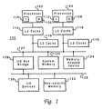
- Data processing system 100 is a symmetric multiprocessor (SMP) system including a plurality of processors 102 and 104, which preferably comprise one of the PowerPCTM family of processors available from International Business Machines of Armonk, New York. Although only two processors are depicted in the exemplary embodiment, those skilled in the art will appreciate that additional processors may be utilized in a multiprocessor data processing system in accordance with the present invention.
- SMP symmetric multiprocessor
- Each processor 102 and 104 includes a level one (L1) data cache 106 and 108, respectively, and an L1 instruction cache 110 and 112, respectively. Although illustrated as bifurcated instruction and data caches in the exemplary embodiment, those skilled in the art will recognize that a single, unified L1 cache may be implemented. In order to minimize data access latency, one or more additional levels of cache memory may be implemented within data processing system 100, such as level two (L2) caches 114 and 116 and level three (L3) caches 118 and 119. The lower cache levels--L2 and L3--are employed to stage data to the L1 caches and typically have progressively larger storage capacities but longer access latencies.
- data caches 106 and 108 and instruction caches 110 and 112 may each have a storage capacity of 32KB and an access latency of approximately 1-2 processor cycles.
- L2 caches 114 and 116 might have a storage capacity of 512KB but an access latency of 5 processor cycles, while L3 caches 118 and 119 may have a storage capacity of 4MB but an access latency of greater than 15 processor cycles.
- L2 caches 114 and 116 and L3 caches 118 and 119 thus serve as intermediate storage between processors 102 and 104 and system memory 120, which typically has a much larger storage capacity but may have an access latency of greater than 50 processor cycles.
- L2 caches 114 and 116 in the example shown are dedicated caches connected between their respective processors 102 and 104 and system memory 120 (via system bus 122 ).
- L3 caches 118 and 119 are depicted as lookaside caches logically vertical with L2 caches 114 and 116 .
- data or instructions may be looked up one of L2 caches 114 or 116 and one of L3 caches 118 and 119 simultaneously, although the data or instructions will only be retrieved from L3 cache 118 or 119 if the respective L2 cache 114 or 116 misses while L3 cache 118 or 119 hits.
- Those skilled in the art will recognize that various permutations of levels and configurations depicted may be implemented.
- L2 caches 114 and 116 and L3 caches 118 and 119 are connected to system memory 120 via system bus 122 .
- a memory mapped device 124 such as a graphics adapter providing a connection for a display (not shown), and input/output (I/O) bus bridge 126 .
- I/O bus bridge 126 couples system bus 122 to I/O bus 128 , which may provide connections for I/O devices 130 and nonvolatile memory 132 .
- System bus 122 , I/O bus bridge 126 , and I/O bus 128 thus form an interconnect coupling the attached devices, for which alternative implementations are known in the art.
- I/O devices 130 comprise conventional peripheral devices including a keyboard, a graphical pointing device such as a mouse or trackball, a display, and a printer, which are interfaced to I/O bus 128 via conventional adapters.
- Non-volatile memory 132 may comprise a hard disk drive and stores an operating system and other software controlling operation of system 100, which are loaded into volatile system memory 120 in response to system 100 being powered on.
- data processing system 100 may include many additional components not shown in Figure 1 , such as serial and parallel ports, connections to networks or attached devices, a memory controller regulating access to system memory 120 , etc. Such modifications and variations are within the scope of the present invention.
- a typical communications transaction on system bus 122 includes a source tag indicating a source of the transaction, a destination tag specifying the intended recipient of the transaction, an address and/or data.
- Each device connected to system bus 122 preferably snoops all communication transactions on system bus 122 , intervening in communications transactions intended for other recipients when necessary and reproducing changes to system memory data duplicated within the device when feasible and appropriate.
- L2 cache 200 may be a n way set associative cache utilizing 32 bit addresses. Accordingly, cache memory or data array 202 within L2 cache 200 comprises a number of congruence classes or rows each containing sufficient memory for storing n cache lines.
- a cache line also referred to as a cache block, is the unit of cache memory which a coherency state describes. Generally a cache line is 32, 64 or 128 B long in contemporary data processing systems.
- Cache directory 204 also contains a number of rows each containing n directory entries, each directory entry associated with a corresponding cache line in the equivalent row of cache memory 202 .
- Each directory entry includes a tag field 206 , a coherency state field 208, a least recently used (LRU) field 210, and an inclusion (I) field 212.
- Tag field 206 is utilized to store the tag field (e.g., bits [0-19]) of the system memory address of the data stored in an associated cache line.
- Coherency state field 208 defines, through a predefined bit combination, the coherency state of the data stored in the associated cache line.
- LRU field 210 indicates how recently the associated cache line has been accessed relative to other cache lines in the congruence class, and thus indicates which cache line should be cast out of the congruence class should the need for replacement of a cache line arise.
- inclusion field 212 indicates whether the associated cache line is also stored in the logically in line L1 cache, such as L1 data caches 106 and 108 and L1 instruction caches 110 and 112 depicted in Figure 1 .
- L2 cache 200 also includes a cache controller 214 which manages storage and retrieval of cache lines from cache memory 202 and updates cache directory 204 .
- Cache controller 214 acts in response to signals received from an associated processor, such as processor 102 or 104 depicted in Figure 1 , or to transactions snooped from the system bus.
- Cache controller 212 thus includes a number of queues, including read queue 216 and write queue 218 in which actions to be performed are placed until resources become available. For example, a local processor may issue a read request to L2 cache 200 as a result of executing a load instruction.
- Cache controller 214 places the read request in an entry within read queue 216, services the request by supplying the requested data to the local processor, and subsequently removes the read request from read queue 216 .
- Cache controller 214 may also place a write request in write queue 218 to update LRU and inclusion fields 210 and 212 , respectively, associated with the cache line containing the requested data.
- a remote processor may initiate a system bus transaction indicating an intent to modify a specified cache line in its local cache.
- Cache controller 214 in response to snooping this transaction from the system bus, may place a request to read cache directory 204 in read queue 216 to determine if the specified cache line is resident within cache memory 204 .
- cache controller 214 initiated an appropriate response on the system bus and, if necessary, places a write request in write queue 218 which, when serviced, updates the coherency field 208 within cache directory 204 associated with the specified cache line.
- write queue 218 Although only one read queue 216 and one write queue 218 are depicted in the exemplary embodiment of Figure 2 , those skilled in the art will realize that the number of queues employed by cache controller 214 is a matter of design choice and that separate queues may be implemented either for cache directory accesses as opposed to cache memory accesses or for signals received from a local processor rather than transactions snooped from the system bus, or both.
- coherency state field 208 of each entry in cache directory 204 is initialized to an invalid (I) state at system power-on to indicate that both the tag field 206 and the data stored in an associated cache line within cache memory 202 are invalid. Thereafter, coherency state field 208 may be updated to a coherency state within the modified MESI coherency protocols described in detail below.
- the state to which coherency state field 208 transitions depends on both the types of memory accesses made by processors in the system and the response of the storage hierarchy to those accesses, also described in greater detail below.
- cache controller 214 Based on a coherency state indicated in coherency state field 208 of a requested cache line, cache controller 214 responds differently to snooped system bus operations indicating that an L3 cache, such as L3 cache 118 depicted in Figure 1 , is deallocating a specified cache line within its cache memory.
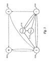
- FIG. 3 a state diagram of a modified MESI cache coherency protocol in accordance with a preferred embodiment of the present invention is depicted.
- the modified MESI protocol is implemented only within an L2 cache; a conventional MESI protocol is implemented in lower cache levels.
- the modified MESI protocol includes the same four basic states utilized in a conventional MESI protocol: modified (M) state 302 , which indicates that the cache line has been modified with respect to corresponding data in system memory without also modifying the system memory data, such that the only valid copy of the data is within the cache entry storing the modified cache line or sector; exclusive (E) state 304 , which indicates that the cache entry is consistent with system memory but is only found, within all caches at that level of the storage hierarchy, in the subject cache; shared (S) state 306 , indicates that the cache entry may be found in the subject cache and at least one other cache at the same level in the storage hierarchy, with all copies of the data being consistent with the corresponding data in system memory; and invalid (I) state 308 , which indicates that a cache entry--both the data and the address tag--within a given cache is no longer coherent with either system memory or other caches in the storage hierarchy. While modified state 302 and exclusive state 304 are supported, the invention relates to cache locations which are presumed to contain instructions
- the modified MESI protocol also includes two additional states, which are variants or sub-states of shared state 306.
- S IC0 state 310 indicates that the cache entry may be found in the subject cache and at least one other cache at the same level in the storage hierarchy, with all copies of the cache entry being consistent with system memory, and also indicates that the subject cache entry was loaded as a result of an instruction fetch.
- S IC1 state 312 indicates that the cache entry may be found in the subject cache and at least one other cache at the same level in the storage hierarchy, with all copies of the cache entry being consistent with system memory, and further indicates both that the subject cache entry was loaded as a result of an instruction fetch and that the same cache entry has been deallocated in lower levels of the storage hierarchy. Despite deallocation by a lower cache, the instructions within the L2 cache entry are maintained for possible access by an L1 cache.
- State transitions within the modified MESI protocol are dependent on both the nature of memory access which prompted the cache entry to be loaded and the nature of the present memory access. If data is stored in a cache location as a result of a data read by a local processor (i.e. a data read operation prompted by a load instruction), then the contents of the cache line are assumed to comprise data and the coherency state transitions from invalid 308 to shared 306 . On the other hand, if the contents of the cache block were retrieved as a result of an instruction fetch, it is assumed that the contents of that cache location comprise instructions and the coherency state transitions from invalid 308 to S IC0 310.
- a cache location in S IC0 state 310 is the subject of a subsequent data read operation initiated by a local processor, the original assumption regarding the cache contents comprising instructions is negated and the coherency state transitions from S IC0 310 to shared 306. Otherwise, however, if a cache entry in S IC0 state 310 is hit by a snooped flush operation, such as may result from deallocation by a lower level cache, the coherency state transitions from S IC0 310 to S IC1 312. Once the coherency state transitions to S IC1 312, subsequent snooped flush hits to the same location are ignored and data read or read with intent to modify (rwitm) operations from a local processor are treated as missed.
- the coherency state transitions occur only within the L2 caches of a data processing system having additional, lower cache levels in the storage hierarchy.
- the same operations cause lower level caches, which follow the conventional MESI protocol, to undergo different coherency state transitions.
- the different coherency state transitions in the L2 and L3 caches which result from various common operations on a particular cache entry are compared below in Table II.
- the L2 cache is inclusive of the present and recent contents of the L1 instruction cache of a local processor, but the L3 cache need not also be inclusive of the same contents.
- Selective inclusivity with regard to instructions is therefore maintained in upper levels of the cache hierarchy while overall cache efficiency is not degraded by requiring complete vertical inclusivity.
- the present invention thus prevents instructions in an L2 cache from being discarded by backward flushes resulting from deallocation in a lower level cache.
- the additional coherency states do not require a substantial increase in overhead, and the modifications need only be implemented within L2 caches in a multilevel cache hierarchy.
- the present invention may be implemented in conjunction with other modifications to the MESI protocol, including the R-MESI protocol in which the recent (R) state, essentially another variant of the shared state, indicates (1) that the cache entry may be found in both the subject cache and at least one other cache at the same level in the storage hierarchy and that all copies of the data in the subject cache and other caches are consistent with the corresponding data in system memory, and (2) that the subject cache, of all caches containing the shared data, most recently received the data in a system bus transaction such as a read from system memory.
- Substates of the recent state indicating that the cache entry is assumed to contain instructions rather than data and/or that the same cache entry has been deallocated in lower level caches may be implemented in a manner equivalent to the S IC0 and S IC1 states.
- the invention may include the following features:
- the method of maintaining cache coherency in a data processing system includes responsive to detecting a data read operation including an address tag associated with the data item while the coherency indicator is in the first state, updating the coherency indicator to a second state indicating that the data item may be found in the first cache and at least one other cache, that all caches containing the data item are coherent with system memory, and that the data item is not presumed to comprise instructions
- the second state may be a shared state.
- the coherency indicator responsive to detecting a snooped flush operation including an address tag associated with the data item while the coherency indicator is in the first state, updating the coherency indicator to a second state indicating that the data item may be found in the first cache, that the first cache is coherent with system memory, and that other caches logically in line and below the first cache do not contain the data item.
- the transition to the second state may result from deallocation of a cache location containing the data item within a second cache logically in line and below the first cache.
- the data processing system may be adapted so that the coherency indicator has a second state indicating that the data item may be found in the second cache and at least one other cache, that all caches containing the data item are coherent with system memory, and that the data item is not presumed to comprise instructions.
- the coherency indicator may transition from the first state to the second state in response to an operation retrieving the data item to a separate data cache within the processor.
- the coherency indicator in the cache supporting a cache coherency protocol in a data processing system may have a second state indicating that the data item within the associated cache location may not be found in other caches logically in line with and below the cache.
- the coherency indicator may have a second state indicating that the data item is not presumed to contain instructions.
Landscapes
- Engineering & Computer Science (AREA)
- Theoretical Computer Science (AREA)
- Physics & Mathematics (AREA)
- General Engineering & Computer Science (AREA)
- General Physics & Mathematics (AREA)
- Memory System Of A Hierarchy Structure (AREA)
Description
- The present invention relates in general to inclusivity in vertical cache hierarchies and in particular to selective inclusivity with respect to cached instructions. Still more particularly, the present invention relates to selective inclusivity to prevent cached instructions from being discarded due to deallocations in lower cache levels.
- Superscalar reduced instruction set (RISC) processors typically include bifurcated data and instruction caches in at least the level one (L1) layer of the storage hierarchy. Separate data and instructions caches are necessary due to the bandwidth required in contemporary superscalar processors, where instruction fetches and data references may easily exceed more than one cache access per processor cycle. L1 caches, which are typically imbedded within the processor hardware and designed for latencies of one processor cycle or less, are therefore usually bifurcated so that instruction and data references may be issued to separate caches during the same processor cycle.
- Many data processing systems may contain multilevel cache hierarchies which are logically in line--that is, caches in higher levels are checked first, with a miss at a higher level prompting access to caches on lower levels. Multilevel caches are typically utilized to stage data to the processor with reduced access latency. Smaller, faster caches are employed in upper levels of the cache hierarchy while larger, slower caches at found in lower levels. Generally, such vertical cache configurations are thought of as inclusive. That is, the contents of each cache includes the contents of the cache immediately above it in the cache hierarchy.
- When space is required within a cache for new data or instructions read from system memory, the cache selects a victim according to the particular replacement policy implemented for the cache and deallocates the selected cache location. In cases where a cache location contained in multiple caches is deallocated in one cache, inclusivity of logically in line caches is maintained by deallocating the same location in other caches. There are circumstances, however, where this produces and undesirable result. For example, if a cache location containing instructions is deallocated within a level three (L3) cache, the same space will generally be deallocated in a level two (L2) cache. If the processor/L1 cache thereafter attempts to reload instructions from the L2 cache, it may miss at the L2 and the L3 caches and (assuming no more levels in the cache hierarchy) be required to access the desired instructions from system memory. Instruction reloads may be necessary, for example, when a mispredicted branch is executed. Since the latency associated with a read from system memory is generally much longer than the latencies associated with the L2 and L3 caches, a significant performance delay may be incurred.
- One problem with preventing instructions from being discarded when cache locations are deallocated is that there exists no clear mechanism for distinguishing instructions from data within a cache. Program source code within system memory may comprise an indistinguishable mixture of instructions and data. This may occur, for example, where a loader program resolves code linkages after loading the code into system memory. Thus, there exists no means for positively identifying instructions when a victim is selected so that a replacement policy may be designed to select an alternative victim. Moreover, it is not necessary that all cache levels be inclusive of the L1 instruction cache. It is simply desirable for an L2 cache to be inclusive of the L1 instruction cache's present and recent contents in order to minimize latency of instruction reloads. Requiring similar inclusivity at all levels of the cache hierarchy detracts from overall cache efficiency.
- EP-A-0681241 discloses a method of maintaining coherency in a data processing system including a system memory and a plurality of caches. The method including performing instruction fetch operations as well as data fetch operations, and setting a coherency indicator of a cache entry to a first state indicating that the cache entry may be found in the first cache and at least one other cache and that all caches containing copies of the cache entry are coherent with main memory.
- "A process-dependent partitioning strategy for cache memories" by Y. Deville, Computer Architecture News, vol. 21, no. 1, 1 March 1993, pages 26-33 discloses a cache with an indication that a cache entry comprises instructions.
- It would be desirable, therefore, to provide a mechanism for maintaining selective inclusivity with regard to instructions in upper levels of the cache hierarchy. It would further be advantageous if the mechanism were not affected by deallocations in lower cache levels, such that instruction cache inclusivity is not required in all cache levels.
- It is therefore one object of the present invention to provide an improved system of inclusivity in vertical cache hierarchies.
- It is another object of the present invention to provide a method and apparatus of providing selective inclusivity with respect to instructions cached in vertical cache hierarchies.
- It is yet another object of the present invention to provide selective inclusivity to prevent cached instructions from being discarded due to deallocations in lower cache levels.
- According to a first aspect of the present invention there is provided a method as defined in
claim 1. - According to a second aspect of the present invention there is provided a data processing system as defined in claim 4.
- According to a third aspect of the present invention there is provided a cache as defined in claim 8.
- The foregoing objects are achieved as is now described. A modified MESI cache coherency protocol is implemented within a level two (L2) cache accessible to a processor having bifurcated level one (L1) data and instruction caches. The modified MESI protocol includes two substates of the shared state, which denote the same coherency information as the shared state plus additional information regarding the contents/coherency of the subject cache entry. One substate, SIC0, indicates that the cache entry is assumed to contain instructions since the contents were retrieved from system memory as a result of an instruction fetch operation. The second substate, SIC1, indicates the same information plus that a snooped flush operation hit the subject cache entry while its coherency was in the first shared substate. Deallocation of a cache entry in the first substate of the shared coherency state within lower level (e.g., L3) caches does not result in the contents of the same cache entry in an L2 cache being invalidated. Once the first substate is entered, the coherency state does not transition to the invalid state unless an operation designed to invalidate instructions is received. Operations from a local processor which contravene the presumption that the contents comprise instructions may cause the coherency state to transition to an ordinary shared state. Since the contents of a cache entry in the two coherency substates are presumed to be instructions, not data, instructions within an L2 cache are not discarded as a result of snooped flushes, but are retained for possible reloads by a local processor.
- The above as well as additional objects, features, and advantages of the present invention will become apparent in the following detailed written description.
- The novel features believed characteristic of the invention are set forth in the appended claims. The invention itself however, as well as a preferred mode of use, further objects and advantages thereof, will best be understood by reference to the following detailed description of an illustrative embodiment when read in conjunction with the accompanying drawings, wherein:
- Figure 1 depicts a multiprocessor data processing system in accordance with a preferred embodiment of the present invention;
- Figure 2 is a block diagram of an L2 cache in accordance with a preferred embodiment of the present invention; and
- Figure 3 depicts a state diagram of a modified MESI cache coherency protocol in accordance with a preferred embodiment of the present invention.
- With reference now to the figures, and in particular with reference to Figure 1, a multiprocessor data processing system in accordance with a preferred embodiment of the present invention is depicted.
Data processing system 100 is a symmetric multiprocessor (SMP) system including a plurality of processors 102 and 104, which preferably comprise one of the PowerPC™ family of processors available from International Business Machines of Armonk, New York. Although only two processors are depicted in the exemplary embodiment, those skilled in the art will appreciate that additional processors may be utilized in a multiprocessor data processing system in accordance with the present invention. - Each processor 102 and 104 includes a level one (L1)
data cache L1 instruction cache 110 and 112, respectively. Although illustrated as bifurcated instruction and data caches in the exemplary embodiment, those skilled in the art will recognize that a single, unified L1 cache may be implemented. In order to minimize data access latency, one or more additional levels of cache memory may be implemented withindata processing system 100, such as level two (L2) caches 114 and 116 and level three (L3) caches 118 and 119. The lower cache levels--L2 and L3--are employed to stage data to the L1 caches and typically have progressively larger storage capacities but longer access latencies. For example,data caches instruction caches 110 and 112 may each have a storage capacity of 32KB and an access latency of approximately 1-2 processor cycles. L2 caches 114 and 116 might have a storage capacity of 512KB but an access latency of 5 processor cycles, while L3 caches 118 and 119 may have a storage capacity of 4MB but an access latency of greater than 15 processor cycles. L2 caches 114 and 116 and L3 caches 118 and 119 thus serve as intermediate storage between processors 102 and 104 andsystem memory 120, which typically has a much larger storage capacity but may have an access latency of greater than 50 processor cycles. - Both the number of levels in the cache hierarchy and the cache hierarchy configuration employed in
data processing system 100 may vary. L2 caches 114 and 116 in the example shown are dedicated caches connected between their respective processors 102 and 104 and system memory 120 (via system bus 122). L3 caches 118 and 119 are depicted as lookaside caches logically vertical with L2 caches 114 and 116. As a result, data or instructions may be looked up one of L2 caches 114 or 116 and one of L3 caches 118 and 119 simultaneously, although the data or instructions will only be retrieved from L3 cache 118 or 119 if the respective L2 cache 114 or 116 misses while L3 cache 118 or 119 hits. Those skilled in the art will recognize that various permutations of levels and configurations depicted may be implemented. - L2 caches 114 and 116 and L3 caches 118 and 119 are connected to
system memory 120 viasystem bus 122. Also connected tosystem bus 122 may be a memory mappeddevice 124, such as a graphics adapter providing a connection for a display (not shown), and input/output (I/O)bus bridge 126. I/O bus bridge 126couples system bus 122 to I/O bus 128, which may provide connections for I/O devices 130 and nonvolatile memory 132.System bus 122, I/O bus bridge 126, and I/O bus 128 thus form an interconnect coupling the attached devices, for which alternative implementations are known in the art. I/O devices 130 comprise conventional peripheral devices including a keyboard, a graphical pointing device such as a mouse or trackball, a display, and a printer, which are interfaced to I/O bus 128 via conventional adapters. Non-volatile memory 132 may comprise a hard disk drive and stores an operating system and other software controlling operation ofsystem 100, which are loaded intovolatile system memory 120 in response tosystem 100 being powered on. Those skilled in the art will recognize thatdata processing system 100 may include many additional components not shown in Figure 1, such as serial and parallel ports, connections to networks or attached devices, a memory controller regulating access tosystem memory 120, etc. Such modifications and variations are within the scope of the present invention. - A typical communications transaction on
system bus 122 includes a source tag indicating a source of the transaction, a destination tag specifying the intended recipient of the transaction, an address and/or data. Each device connected tosystem bus 122 preferably snoops all communication transactions onsystem bus 122, intervening in communications transactions intended for other recipients when necessary and reproducing changes to system memory data duplicated within the device when feasible and appropriate. - Referring to Figure 2, a block diagram of an L2 cache in accordance with a preferred embodiment of the present invention is illustrated. The present invention supports pseudo-precise instruction cache inclusivity within L2 caches, such as L2 caches 114 and 116 depicted in Figure 1, by implementing a modified version of the MESI cache coherency protocols as described in connection with the state diagram depicted in Figure 3.
L2 cache 200 may be a n way set associative cache utilizing 32 bit addresses. Accordingly, cache memory ordata array 202 withinL2 cache 200 comprises a number of congruence classes or rows each containing sufficient memory for storing n cache lines. A cache line, also referred to as a cache block, is the unit of cache memory which a coherency state describes. Generally a cache line is 32, 64 or 128 B long in contemporary data processing systems. -
Cache directory 204 also contains a number of rows each containing n directory entries, each directory entry associated with a corresponding cache line in the equivalent row ofcache memory 202. Each directory entry includes atag field 206, acoherency state field 208, a least recently used (LRU)field 210, and an inclusion (I)field 212.Tag field 206 is utilized to store the tag field (e.g., bits [0-19]) of the system memory address of the data stored in an associated cache line.Coherency state field 208 defines, through a predefined bit combination, the coherency state of the data stored in the associated cache line.LRU field 210 indicates how recently the associated cache line has been accessed relative to other cache lines in the congruence class, and thus indicates which cache line should be cast out of the congruence class should the need for replacement of a cache line arise. Finally,inclusion field 212 indicates whether the associated cache line is also stored in the logically in line L1 cache, such asL1 data caches L1 instruction caches 110 and 112 depicted in Figure 1. - Still referring to Figure 2,
L2 cache 200 also includes acache controller 214 which manages storage and retrieval of cache lines fromcache memory 202 andupdates cache directory 204.Cache controller 214 acts in response to signals received from an associated processor, such as processor 102 or 104 depicted in Figure 1, or to transactions snooped from the system bus.Cache controller 212 thus includes a number of queues, includingread queue 216 and writequeue 218 in which actions to be performed are placed until resources become available. For example, a local processor may issue a read request toL2 cache 200 as a result of executing a load instruction.Cache controller 214 places the read request in an entry withinread queue 216, services the request by supplying the requested data to the local processor, and subsequently removes the read request fromread queue 216.Cache controller 214 may also place a write request inwrite queue 218 to update LRU andinclusion fields Cache controller 214, in response to snooping this transaction from the system bus, may place a request to readcache directory 204 inread queue 216 to determine if the specified cache line is resident withincache memory 204. If so,cache controller 214 initiated an appropriate response on the system bus and, if necessary, places a write request inwrite queue 218 which, when serviced, updates thecoherency field 208 withincache directory 204 associated with the specified cache line. Although only oneread queue 216 and onewrite queue 218 are depicted in the exemplary embodiment of Figure 2, those skilled in the art will realize that the number of queues employed bycache controller 214 is a matter of design choice and that separate queues may be implemented either for cache directory accesses as opposed to cache memory accesses or for signals received from a local processor rather than transactions snooped from the system bus, or both. - In a preferred embodiment,
coherency state field 208 of each entry incache directory 204 is initialized to an invalid (I) state at system power-on to indicate that both thetag field 206 and the data stored in an associated cache line withincache memory 202 are invalid. Thereafter,coherency state field 208 may be updated to a coherency state within the modified MESI coherency protocols described in detail below. The state to whichcoherency state field 208 transitions depends on both the types of memory accesses made by processors in the system and the response of the storage hierarchy to those accesses, also described in greater detail below. Based on a coherency state indicated incoherency state field 208 of a requested cache line,cache controller 214 responds differently to snooped system bus operations indicating that an L3 cache, such as L3 cache 118 depicted in Figure 1, is deallocating a specified cache line within its cache memory. - With reference now to Figure 3, a state diagram of a modified MESI cache coherency protocol in accordance with a preferred embodiment of the present invention is depicted. The modified MESI protocol is implemented only within an L2 cache; a conventional MESI protocol is implemented in lower cache levels. The modified MESI protocol includes the same four basic states utilized in a conventional MESI protocol: modified (M)
state 302, which indicates that the cache line has been modified with respect to corresponding data in system memory without also modifying the system memory data, such that the only valid copy of the data is within the cache entry storing the modified cache line or sector; exclusive (E)state 304, which indicates that the cache entry is consistent with system memory but is only found, within all caches at that level of the storage hierarchy, in the subject cache; shared (S) state 306, indicates that the cache entry may be found in the subject cache and at least one other cache at the same level in the storage hierarchy, with all copies of the data being consistent with the corresponding data in system memory; and invalid (I)state 308, which indicates that a cache entry--both the data and the address tag--within a given cache is no longer coherent with either system memory or other caches in the storage hierarchy. While modifiedstate 302 andexclusive state 304 are supported, the invention relates to cache locations which are presumed to contain instructions rather than data. Therefore, these states should not be applicable to the cache locations of interest and will not be described fully herein. - The modified MESI protocol also includes two additional states, which are variants or sub-states of shared state 306. SIC0 state 310 indicates that the cache entry may be found in the subject cache and at least one other cache at the same level in the storage hierarchy, with all copies of the cache entry being consistent with system memory, and also indicates that the subject cache entry was loaded as a result of an instruction fetch. SIC1 state 312 indicates that the cache entry may be found in the subject cache and at least one other cache at the same level in the storage hierarchy, with all copies of the cache entry being consistent with system memory, and further indicates both that the subject cache entry was loaded as a result of an instruction fetch and that the same cache entry has been deallocated in lower levels of the storage hierarchy. Despite deallocation by a lower cache, the instructions within the L2 cache entry are maintained for possible access by an L1 cache.
- State transitions within the modified MESI protocol are dependent on both the nature of memory access which prompted the cache entry to be loaded and the nature of the present memory access. If data is stored in a cache location as a result of a data read by a local processor (i.e. a data read operation prompted by a load instruction), then the contents of the cache line are assumed to comprise data and the coherency state transitions from invalid 308 to shared 306. On the other hand, if the contents of the cache block were retrieved as a result of an instruction fetch, it is assumed that the contents of that cache location comprise instructions and the coherency state transitions from invalid 308 to
S IC0 310. If a cache location in SIC0 state 310 is the subject of a subsequent data read operation initiated by a local processor, the original assumption regarding the cache contents comprising instructions is negated and the coherency state transitions fromS IC0 310 to shared 306. Otherwise, however, if a cache entry in SIC0 state 310 is hit by a snooped flush operation, such as may result from deallocation by a lower level cache, the coherency state transitions fromS IC0 310 toS IC1 312. Once the coherency state transitions toS IC1 312, subsequent snooped flush hits to the same location are ignored and data read or read with intent to modify (rwitm) operations from a local processor are treated as missed. From either SIC0 state 310 or SIC1 state 312, the coherency state transitions toinvalid state 308 only as a result of an instruction cache block invalidate (icbi) or equivalent operation. State transitions which may be made in the modified MESI protocol depicted in Figure 3 are summarized below in Table I.Table I State transition Causes Notes I - S data read or rwitm Cache entry not believed to contain instructions I - SIC0 instruction fetch Cache entry assumed to contain instructions S - I snooped flush SIC0 - S data read Cache entry not believed to contain instructions SIC0 - I instruction cache block invalidate SIC0 - SIC1 snooped flush Lower level cache deallocation SIC1 - I instruction cache block invalidate - The coherency state transitions occur only within the L2 caches of a data processing system having additional, lower cache levels in the storage hierarchy. The same operations cause lower level caches, which follow the conventional MESI protocol, to undergo different coherency state transitions. The different coherency state transitions in the L2 and L3 caches which result from various common operations on a particular cache entry are compared below in Table II.
Table II Operation L2 L3 I-fetch I - SIC0 I - S data read SIC0 - S S - S snooped flush SIC0 - SIC1 S - I
Although described above as a modification only of the conventional MESI protocol, the present invention may be implemented in conjunction with other modifications to the MESI protocol, including the R-MESI protocol in which the recent (R) state, essentially another variant of the shared state, indicates (1) that the cache entry may be found in both the subject cache and at least one other cache at the same level in the storage hierarchy and that all copies of the data in the subject cache and other caches are consistent with the corresponding data in system memory, and (2) that the subject cache, of all caches containing the shared data, most recently received the data in a system bus transaction such as a read from system memory. Substates of the recent state indicating that the cache entry is assumed to contain instructions rather than data and/or that the same cache entry has been deallocated in lower level caches may be implemented in a manner equivalent to the SIC0 and SIC1 states. - The invention may include the following features:
- The method of maintaining cache coherency in a data processing system includes responsive to detecting a data read operation including an address tag associated with the data item while the coherency indicator is in the first state, updating the coherency indicator to a second state indicating that the data item may be found in the first cache and at least one other cache, that all caches containing the data item are coherent with system memory, and that the data item is not presumed to comprise instructions
- The second state may be a shared state.
- Further, responsive to detecting a snooped flush operation including an address tag associated with the data item while the coherency indicator is in the first state, updating the coherency indicator to a second state indicating that the data item may be found in the first cache, that the first cache is coherent with system memory, and that other caches logically in line and below the first cache do not contain the data item. The transition to the second state may result from deallocation of a cache location containing the data item within a second cache logically in line and below the first cache.
- Also, responsive to detecting an operation invalidating an instruction cache location and including an address tag associated with the data item while the coherency indicator is in the second state, updating the coherency indicator to a third state indicating that the data item is invalid.
- The data processing system may be adapted so that the coherency indicator has a second state indicating that the data item may be found in the second cache and at least one other cache, that all caches containing the data item are coherent with system memory, and that the data item is not presumed to comprise instructions.
- The coherency indicator may transition from the first state to the second state in response to an operation retrieving the data item to a separate data cache within the processor.
- The coherency indicator in the cache supporting a cache coherency protocol in a data processing system may have a second state indicating that the data item within the associated cache location may not be found in other caches logically in line with and below the cache. The coherency indicator may have a second state indicating that the data item is not presumed to contain instructions.
Claims (8)
- A method of maintaining cache coherency in a data processing system including at least two processors, a system memory (120) and at least two cache hierarchies each having a level one cache (106, 108), a level two cache (114, 116) and at least one logically lower-level cache (118, 119); the method including setting a coherency indicator (208) associated with a cache entry within a level two cache (114, 116) to a first state (310) indicating that the cache entry may be found in the the level two cache (114, 116) and at least one other cache at the same level in another cache hierarchy, that all caches containing the cache entry are coherent with system memory, and that the cache entry was retrieved by an instruction fetch operation; and wherein a cache entry indicated by the first state is not discarded by backward flushes resulting from deallocation in the at least one logically lower-level cache (118, 119).
- A method of claim 1, characterised in that the first state (310) is a shared state resulting from an instruction fetch operation.
- A method of claim 1, characterised by responsive to detecting an operation invalidating an instruction cache location and including an address tag associated with the cache entry while the coherency indicator (208) is in the first state (310), updating the coherency indicator to a second state (308) indicating that the cache entry is invalid.
- A data processing system including at least two processors, a system memory (120) and at least two cache hierarchies each comprising a level one cache (106, 108), a level two cache (114, 116) and at least one logically lower-level cache (118, 119); a coherency indicator (204) is provided associated with a cache entry within a level two cache (114, 116), the coherency indicator having a first state (310) indicating that the cache entry may be found in the level two cache (114, 116) and at least one other cache at the same level in another cache hierarchy, that all caches containing the cache entry are coherent with system memory, and that the cache entry was retrieved by an instruction fetch operation; and wherein a cache entry indicated by the first state is not discarded by backward flushes resulting from deallocation in the at least one logically lower-level cache (118, 119).
- A data processing system of claim 4, characterised in that the coherency indicator has a second state (312) indicating that the cache entry may be found in the level two cache but not in the at least one logically lower level cache.
- A data processing system of claim 5, characterised in that the level one cache (106,108) comprises an instruction cache separate from a data cache in the processor, and the coherency indicator (208) has a third state (308) indicating that the cache entry is invalid, the coherency indicator transitioning from the second state to the third state in response to an operation invalidating a cache location in the level one cache.
- A data processing system of claim 4, characterised in that the level one cache (106,108) comprises an instruction cache separate from a data cache in the processor, and the coherency indicator (208) has a second state (308) indicating that the cache entry is invalid, the coherency indicator transitioning from the first state to the second state in response to an operation invalidating a cache location in the level one cache.
- A cache for use in a cache hierarchy including at least a level one cache (106, 108) and a level two cache (114, 116); and at least one logically lower-level cache (118, 119); said cache being a level two cache and supporting a cache coherency protocol in a data processing system (100) having at least two processors, a system memory and at least two cache hierarchies, and comprising:data storage including a plurality of cache locations;a cache directory (204) including a plurality of entries, each directory entry uniquely associated with a cache location within the plurality of cache locations; anda coherency indicator (208) within at least one directory entry, the coherency indicator having a first state (310) indicating that the cache entry may be found in the cache (114, 116) and at least one other cache at the same level in another cache hierarchy, that all caches containing the cache entry are coherent with system memory, and that the cache entry was retrieved by an instruction fetch operation; and wherein a cache entry indicated by the first state is not discarded by backward flushes resulting from deallocation in the at least one logically lower-level cache (118, 119).
Applications Claiming Priority (2)
| Application Number | Priority Date | Filing Date | Title |
|---|---|---|---|
| US09/024,321 US6345339B1 (en) | 1998-02-17 | 1998-02-17 | Pseudo precise I-cache inclusivity for vertical caches |
| US24321 | 1998-02-17 |
Publications (3)
| Publication Number | Publication Date |
|---|---|
| EP0936552A2 EP0936552A2 (en) | 1999-08-18 |
| EP0936552A3 EP0936552A3 (en) | 1999-09-22 |
| EP0936552B1 true EP0936552B1 (en) | 2006-04-26 |
Family
ID=21819988
Family Applications (1)
| Application Number | Title | Priority Date | Filing Date |
|---|---|---|---|
| EP99301051A Expired - Lifetime EP0936552B1 (en) | 1998-02-17 | 1999-02-15 | Pseudo precise I-cache inclusivity for vertical caches |
Country Status (10)
| Country | Link |
|---|---|
| US (1) | US6345339B1 (en) |
| EP (1) | EP0936552B1 (en) |
| JP (1) | JP3245125B2 (en) |
| KR (1) | KR100320974B1 (en) |
| CN (1) | CN1134735C (en) |
| CA (1) | CA2260285A1 (en) |
| DE (1) | DE69930983T2 (en) |
| MY (1) | MY119935A (en) |
| SG (1) | SG71192A1 (en) |
| TW (1) | TW428133B (en) |
Families Citing this family (20)
| Publication number | Priority date | Publication date | Assignee | Title |
|---|---|---|---|---|
| JP3540255B2 (en) | 1999-09-28 | 2004-07-07 | シャープ株式会社 | Method for repairing conduction failure of liquid crystal display device |
| US6748490B1 (en) * | 2000-03-29 | 2004-06-08 | Ati International Srl | Method and apparatus for maintaining data coherency in a shared memory system |
| US7117316B2 (en) * | 2002-08-05 | 2006-10-03 | Micron Technology, Inc. | Memory hub and access method having internal row caching |
| US6993628B2 (en) * | 2003-04-28 | 2006-01-31 | International Business Machines Corporation | Cache allocation mechanism for saving elected unworthy member via substitute victimization and imputed worthiness of substitute victim member |
| US6996679B2 (en) * | 2003-04-28 | 2006-02-07 | International Business Machines Corporation | Cache allocation mechanism for saving multiple elected unworthy members via substitute victimization and imputed worthiness of multiple substitute victim members |
| US7484044B2 (en) | 2003-09-12 | 2009-01-27 | Intel Corporation | Method and apparatus for joint cache coherency states in multi-interface caches |
| US7426612B2 (en) * | 2004-06-30 | 2008-09-16 | Intel Corporation | Methods and apparatus for enforcing instruction-cache coherence |
| US7418557B2 (en) * | 2004-11-30 | 2008-08-26 | International Business Machines Corporation | Managing multiprocessor operations |
| US20070094450A1 (en) * | 2005-10-26 | 2007-04-26 | International Business Machines Corporation | Multi-level cache architecture having a selective victim cache |
| US7836257B2 (en) * | 2007-12-19 | 2010-11-16 | International Business Machines Corpation | System and method for cache line replacement selection in a multiprocessor environment |
| US8055847B2 (en) * | 2008-07-07 | 2011-11-08 | International Business Machines Corporation | Efficient processing of data requests with the aid of a region cache |
| CN106681938B (en) * | 2012-10-22 | 2020-08-18 | 英特尔公司 | Apparatus and system for controlling messaging in a multi-slot link layer microchip |
| US9563562B2 (en) | 2012-11-27 | 2017-02-07 | Nvidia Corporation | Page crossing prefetches |
| US9639471B2 (en) | 2012-11-27 | 2017-05-02 | Nvidia Corporation | Prefetching according to attributes of access requests |
| US9824009B2 (en) | 2012-12-21 | 2017-11-21 | Nvidia Corporation | Information coherency maintenance systems and methods |
| CN104978283B (en) * | 2014-04-10 | 2018-06-05 | 华为技术有限公司 | A kind of memory access control method and device |
| US9852071B2 (en) | 2014-10-20 | 2017-12-26 | International Business Machines Corporation | Granting exclusive cache access using locality cache coherency state |
| PL3552108T3 (en) * | 2016-12-12 | 2022-01-03 | Intel Corporation | Apparatuses and methods for a processor architecture |
| US10282296B2 (en) | 2016-12-12 | 2019-05-07 | Intel Corporation | Zeroing a cache line |
| CN119375664B (en) * | 2024-09-30 | 2025-07-25 | 兆讯恒达科技股份有限公司 | SoC cache testing method for testability design |
Family Cites Families (11)
| Publication number | Priority date | Publication date | Assignee | Title |
|---|---|---|---|---|
| US5553262B1 (en) * | 1988-01-21 | 1999-07-06 | Mitsubishi Electric Corp | Memory apparatus and method capable of setting attribute of information to be cached |
| US5023776A (en) * | 1988-02-22 | 1991-06-11 | International Business Machines Corp. | Store queue for a tightly coupled multiple processor configuration with two-level cache buffer storage |
| US5317716A (en) * | 1988-08-16 | 1994-05-31 | International Business Machines Corporation | Multiple caches using state information indicating if cache line was previously modified and type of access rights granted to assign access rights to cache line |
| US5319766A (en) * | 1992-04-24 | 1994-06-07 | Digital Equipment Corporation | Duplicate tag store for a processor having primary and backup cache memories in a multiprocessor computer system |
| CA2148186A1 (en) | 1994-05-04 | 1995-11-05 | Michael T. Jackson | Processor board having a second level writeback cache system and a third level writethrough cache system which stores exclusive state information for use in a multiprocessor computer system |
| US5551001A (en) * | 1994-06-29 | 1996-08-27 | Exponential Technology, Inc. | Master-slave cache system for instruction and data cache memories |
| JP3132749B2 (en) * | 1994-12-05 | 2001-02-05 | インターナショナル・ビジネス・マシーンズ・コーポレ−ション | Multiprocessor data processing system |
| US5809529A (en) * | 1995-08-23 | 1998-09-15 | International Business Machines Corporation | Prefetching of committed instructions from a memory to an instruction cache |
| US6374330B1 (en) * | 1997-04-14 | 2002-04-16 | International Business Machines Corporation | Cache-coherency protocol with upstream undefined state |
| US5996048A (en) * | 1997-06-20 | 1999-11-30 | Sun Microsystems, Inc. | Inclusion vector architecture for a level two cache |
| US6199144B1 (en) * | 1997-12-31 | 2001-03-06 | Intel Corporation | Method and apparatus for transferring data in a computer system |
-
1998
- 1998-02-17 US US09/024,321 patent/US6345339B1/en not_active Expired - Fee Related
-
1999
- 1999-01-15 CN CNB991010981A patent/CN1134735C/en not_active Expired - Fee Related
- 1999-01-15 MY MYPI99000183A patent/MY119935A/en unknown
- 1999-01-25 CA CA002260285A patent/CA2260285A1/en not_active Abandoned
- 1999-02-09 JP JP03158699A patent/JP3245125B2/en not_active Expired - Fee Related
- 1999-02-10 TW TW088102029A patent/TW428133B/en not_active IP Right Cessation
- 1999-02-11 KR KR1019990004876A patent/KR100320974B1/en not_active Expired - Fee Related
- 1999-02-13 SG SG1999000590A patent/SG71192A1/en unknown
- 1999-02-15 EP EP99301051A patent/EP0936552B1/en not_active Expired - Lifetime
- 1999-02-15 DE DE69930983T patent/DE69930983T2/en not_active Expired - Lifetime
Also Published As
| Publication number | Publication date |
|---|---|
| JPH11328024A (en) | 1999-11-30 |
| JP3245125B2 (en) | 2002-01-07 |
| SG71192A1 (en) | 2000-03-21 |
| MY119935A (en) | 2005-08-30 |
| CN1134735C (en) | 2004-01-14 |
| EP0936552A2 (en) | 1999-08-18 |
| KR19990072592A (en) | 1999-09-27 |
| CA2260285A1 (en) | 1999-08-17 |
| EP0936552A3 (en) | 1999-09-22 |
| KR100320974B1 (en) | 2002-01-18 |
| DE69930983T2 (en) | 2006-11-23 |
| US6345339B1 (en) | 2002-02-05 |
| TW428133B (en) | 2001-04-01 |
| DE69930983D1 (en) | 2006-06-01 |
| CN1231443A (en) | 1999-10-13 |
Similar Documents
| Publication | Publication Date | Title |
|---|---|---|
| EP0936552B1 (en) | Pseudo precise I-cache inclusivity for vertical caches | |
| US7698508B2 (en) | System and method for reducing unnecessary cache operations | |
| US6195729B1 (en) | Deallocation with cache update protocol (L2 evictions) | |
| US8909871B2 (en) | Data processing system and method for reducing cache pollution by write stream memory access patterns | |
| EP0695996B1 (en) | Multi-level cache system | |
| US6957304B2 (en) | Runahead allocation protection (RAP) | |
| US7032074B2 (en) | Method and mechanism to use a cache to translate from a virtual bus to a physical bus | |
| US6725341B1 (en) | Cache line pre-load and pre-own based on cache coherence speculation | |
| KR100326980B1 (en) | Cache coherency protocol for a data processing system including a multi-level memory hierarchy | |
| US5829038A (en) | Backward inquiry to lower level caches prior to the eviction of a modified line from a higher level cache in a microprocessor hierarchical cache structure | |
| US6078992A (en) | Dirty line cache | |
| US6185658B1 (en) | Cache with enhanced victim selection using the coherency states of cache lines | |
| JP2000250812A (en) | Memory cache system and managing method therefor | |
| US6321306B1 (en) | High performance multiprocessor system with modified-unsolicited cache state | |
| JP3262519B2 (en) | Method and system for enhancing processor memory performance by removing old lines in second level cache | |
| US8621152B1 (en) | Transparent level 2 cache that uses independent tag and valid random access memory arrays for cache access | |
| KR100322225B1 (en) | Cache coherency protocol having hovering(h) and recent(r) states | |
| US20060277366A1 (en) | System and method of managing cache hierarchies with adaptive mechanisms | |
| US8473686B2 (en) | Computer cache system with stratified replacement | |
| US6347363B1 (en) | Merged vertical cache controller mechanism with combined cache controller and snoop queries for in-line caches | |
| US6275908B1 (en) | Cache coherency protocol including an HR state | |
| US6349367B1 (en) | Method and system for communication in which a castout operation is cancelled in response to snoop responses | |
| US6256710B1 (en) | Cache management during cache inhibited transactions for increasing cache efficiency | |
| US6272603B1 (en) | Cache coherency protocol having hovering (H), recent (R), and tagged (T) states | |
| US6349369B1 (en) | Protocol for transferring modified-unsolicited state during data intervention |
Legal Events
| Date | Code | Title | Description |
|---|---|---|---|
| PUAI | Public reference made under article 153(3) epc to a published international application that has entered the european phase |
Free format text: ORIGINAL CODE: 0009012 |
|
| PUAL | Search report despatched |
Free format text: ORIGINAL CODE: 0009013 |
|
| AK | Designated contracting states |
Kind code of ref document: A2 Designated state(s): BE CH DE ES FR GB IE IT LI NL SE |
|
| AX | Request for extension of the european patent |
Free format text: AL;LT;LV;MK;RO;SI |
|
| AK | Designated contracting states |
Kind code of ref document: A3 Designated state(s): AT BE CH CY DE DK ES FI FR GB GR IE IT LI LU MC NL PT SE |
|
| AX | Request for extension of the european patent |
Free format text: AL;LT;LV;MK;RO;SI |
|
| 17P | Request for examination filed |
Effective date: 20000317 |
|
| AKX | Designation fees paid |
Free format text: BE CH DE ES FR GB IE IT LI NL SE |
|
| 17Q | First examination report despatched |
Effective date: 20001215 |
|
| GRAP | Despatch of communication of intention to grant a patent |
Free format text: ORIGINAL CODE: EPIDOSNIGR1 |
|
| GRAS | Grant fee paid |
Free format text: ORIGINAL CODE: EPIDOSNIGR3 |
|
| GRAA | (expected) grant |
Free format text: ORIGINAL CODE: 0009210 |
|
| AK | Designated contracting states |
Kind code of ref document: B1 Designated state(s): BE CH DE ES FR GB IE IT LI NL SE |
|
| PG25 | Lapsed in a contracting state [announced via postgrant information from national office to epo] |
Ref country code: NL Free format text: LAPSE BECAUSE OF FAILURE TO SUBMIT A TRANSLATION OF THE DESCRIPTION OR TO PAY THE FEE WITHIN THE PRESCRIBED TIME-LIMIT Effective date: 20060426 Ref country code: LI Free format text: LAPSE BECAUSE OF FAILURE TO SUBMIT A TRANSLATION OF THE DESCRIPTION OR TO PAY THE FEE WITHIN THE PRESCRIBED TIME-LIMIT Effective date: 20060426 Ref country code: IT Free format text: LAPSE BECAUSE OF FAILURE TO SUBMIT A TRANSLATION OF THE DESCRIPTION OR TO PAY THE FEE WITHIN THE PRESCRIBED TIME-LIMIT;WARNING: LAPSES OF ITALIAN PATENTS WITH EFFECTIVE DATE BEFORE 2007 MAY HAVE OCCURRED AT ANY TIME BEFORE 2007. THE CORRECT EFFECTIVE DATE MAY BE DIFFERENT FROM THE ONE RECORDED. Effective date: 20060426 Ref country code: CH Free format text: LAPSE BECAUSE OF FAILURE TO SUBMIT A TRANSLATION OF THE DESCRIPTION OR TO PAY THE FEE WITHIN THE PRESCRIBED TIME-LIMIT Effective date: 20060426 Ref country code: BE Free format text: LAPSE BECAUSE OF FAILURE TO SUBMIT A TRANSLATION OF THE DESCRIPTION OR TO PAY THE FEE WITHIN THE PRESCRIBED TIME-LIMIT Effective date: 20060426 |
|
| REG | Reference to a national code |
Ref country code: GB Ref legal event code: FG4D |
|
| REG | Reference to a national code |
Ref country code: IE Ref legal event code: FG4D |
|
| REF | Corresponds to: |
Ref document number: 69930983 Country of ref document: DE Date of ref document: 20060601 Kind code of ref document: P |
|
| PG25 | Lapsed in a contracting state [announced via postgrant information from national office to epo] |
Ref country code: SE Free format text: LAPSE BECAUSE OF FAILURE TO SUBMIT A TRANSLATION OF THE DESCRIPTION OR TO PAY THE FEE WITHIN THE PRESCRIBED TIME-LIMIT Effective date: 20060726 |
|
| PG25 | Lapsed in a contracting state [announced via postgrant information from national office to epo] |
Ref country code: ES Free format text: LAPSE BECAUSE OF FAILURE TO SUBMIT A TRANSLATION OF THE DESCRIPTION OR TO PAY THE FEE WITHIN THE PRESCRIBED TIME-LIMIT Effective date: 20060806 |
|
| REG | Reference to a national code |
Ref country code: CH Ref legal event code: PL |
|
| NLV1 | Nl: lapsed or annulled due to failure to fulfill the requirements of art. 29p and 29m of the patents act | ||
| ET | Fr: translation filed | ||
| PLBE | No opposition filed within time limit |
Free format text: ORIGINAL CODE: 0009261 |
|
| STAA | Information on the status of an ep patent application or granted ep patent |
Free format text: STATUS: NO OPPOSITION FILED WITHIN TIME LIMIT |
|
| 26N | No opposition filed |
Effective date: 20070129 |
|
| PG25 | Lapsed in a contracting state [announced via postgrant information from national office to epo] |
Ref country code: IE Free format text: LAPSE BECAUSE OF NON-PAYMENT OF DUE FEES Effective date: 20070215 |
|
| REG | Reference to a national code |
Ref country code: GB Ref legal event code: 746 Effective date: 20080117 |
|
| PGFP | Annual fee paid to national office [announced via postgrant information from national office to epo] |
Ref country code: FR Payment date: 20110216 Year of fee payment: 13 |
|
| REG | Reference to a national code |
Ref country code: FR Ref legal event code: ST Effective date: 20121031 |
|
| PG25 | Lapsed in a contracting state [announced via postgrant information from national office to epo] |
Ref country code: FR Free format text: LAPSE BECAUSE OF NON-PAYMENT OF DUE FEES Effective date: 20120229 |
|
| PGFP | Annual fee paid to national office [announced via postgrant information from national office to epo] |
Ref country code: GB Payment date: 20170130 Year of fee payment: 19 |
|
| PGFP | Annual fee paid to national office [announced via postgrant information from national office to epo] |
Ref country code: DE Payment date: 20180201 Year of fee payment: 20 |
|
| GBPC | Gb: european patent ceased through non-payment of renewal fee |
Effective date: 20180215 |
|
| REG | Reference to a national code |
Ref country code: DE Ref legal event code: R071 Ref document number: 69930983 Country of ref document: DE |
|
| PG25 | Lapsed in a contracting state [announced via postgrant information from national office to epo] |
Ref country code: GB Free format text: LAPSE BECAUSE OF NON-PAYMENT OF DUE FEES Effective date: 20180215 |