EP0936392A2 - Metal bellows and its method of manufacture - Google Patents
Metal bellows and its method of manufacture Download PDFInfo
- Publication number
- EP0936392A2 EP0936392A2 EP99103002A EP99103002A EP0936392A2 EP 0936392 A2 EP0936392 A2 EP 0936392A2 EP 99103002 A EP99103002 A EP 99103002A EP 99103002 A EP99103002 A EP 99103002A EP 0936392 A2 EP0936392 A2 EP 0936392A2
- Authority
- EP
- European Patent Office
- Prior art keywords
- bellows
- ring element
- blank
- ring
- deformation
- Prior art date
- Legal status (The legal status is an assumption and is not a legal conclusion. Google has not performed a legal analysis and makes no representation as to the accuracy of the status listed.)
- Withdrawn
Links
Images


Classifications
-
- F—MECHANICAL ENGINEERING; LIGHTING; HEATING; WEAPONS; BLASTING
- F16—ENGINEERING ELEMENTS AND UNITS; GENERAL MEASURES FOR PRODUCING AND MAINTAINING EFFECTIVE FUNCTIONING OF MACHINES OR INSTALLATIONS; THERMAL INSULATION IN GENERAL
- F16L—PIPES; JOINTS OR FITTINGS FOR PIPES; SUPPORTS FOR PIPES, CABLES OR PROTECTIVE TUBING; MEANS FOR THERMAL INSULATION IN GENERAL
- F16L23/00—Flanged joints
- F16L23/04—Flanged joints the flanges being connected by members tensioned in the radial plane
-
- F—MECHANICAL ENGINEERING; LIGHTING; HEATING; WEAPONS; BLASTING
- F16—ENGINEERING ELEMENTS AND UNITS; GENERAL MEASURES FOR PRODUCING AND MAINTAINING EFFECTIVE FUNCTIONING OF MACHINES OR INSTALLATIONS; THERMAL INSULATION IN GENERAL
- F16L—PIPES; JOINTS OR FITTINGS FOR PIPES; SUPPORTS FOR PIPES, CABLES OR PROTECTIVE TUBING; MEANS FOR THERMAL INSULATION IN GENERAL
- F16L25/00—Constructive types of pipe joints not provided for in groups F16L13/00 - F16L23/00 ; Details of pipe joints not otherwise provided for, e.g. electrically conducting or insulating means
- F16L25/0036—Joints for corrugated pipes
-
- F—MECHANICAL ENGINEERING; LIGHTING; HEATING; WEAPONS; BLASTING
- F16—ENGINEERING ELEMENTS AND UNITS; GENERAL MEASURES FOR PRODUCING AND MAINTAINING EFFECTIVE FUNCTIONING OF MACHINES OR INSTALLATIONS; THERMAL INSULATION IN GENERAL
- F16L—PIPES; JOINTS OR FITTINGS FOR PIPES; SUPPORTS FOR PIPES, CABLES OR PROTECTIVE TUBING; MEANS FOR THERMAL INSULATION IN GENERAL
- F16L27/00—Adjustable joints, Joints allowing movement
- F16L27/10—Adjustable joints, Joints allowing movement comprising a flexible connection only, e.g. for damping vibrations
- F16L27/107—Adjustable joints, Joints allowing movement comprising a flexible connection only, e.g. for damping vibrations the ends of the pipe being interconnected by a flexible sleeve
- F16L27/11—Adjustable joints, Joints allowing movement comprising a flexible connection only, e.g. for damping vibrations the ends of the pipe being interconnected by a flexible sleeve the sleeve having the form of a bellows with multiple corrugations
-
- F—MECHANICAL ENGINEERING; LIGHTING; HEATING; WEAPONS; BLASTING
- F16—ENGINEERING ELEMENTS AND UNITS; GENERAL MEASURES FOR PRODUCING AND MAINTAINING EFFECTIVE FUNCTIONING OF MACHINES OR INSTALLATIONS; THERMAL INSULATION IN GENERAL
- F16L—PIPES; JOINTS OR FITTINGS FOR PIPES; SUPPORTS FOR PIPES, CABLES OR PROTECTIVE TUBING; MEANS FOR THERMAL INSULATION IN GENERAL
- F16L51/00—Expansion-compensation arrangements for pipe-lines
- F16L51/02—Expansion-compensation arrangements for pipe-lines making use of bellows or an expansible folded or corrugated tube
- F16L51/025—Expansion-compensation arrangements for pipe-lines making use of bellows or an expansible folded or corrugated tube with several corrugations
Definitions
- the invention relates to a method for producing a compound with a suitable metal bellows counterpart, in which a tubular Blank by alternating force application to a bellows successive annular bulges and indentations deformed is, as well as a metal bellows produced by such a method.
- Metal bellows of the specified type are used for compensation in pipelines of thermal expansion, for sound absorption, for the isolation of pipe vibrations and to compensate for assembly tolerances.
- the metal bellows are usually with their end faces with each connected to a pipeline. Due to the stretchability or compressibility of the Metal bellows can then relative movements of the pipes to each other or different distances between these pipes be balanced.
- Typical areas of application for connecting pipes by means of metal bellows z. B. vacuum technology, thermal solar systems for domestic water heating and process heat generation, heating and hot water systems, process engineering systems, district heating pipes, Pipelines and energy systems.
- a ring element on a cylindrical end portion of a metal bellows postpone and then the metal bellows in its cylindrical Flare end area. Through the flared end of the metal bellows then prevents the ring member from the cylindrical end of the metal bellows can be deducted again. That in the manner mentioned on Metal bellows fixed ring element can then with a suitable counterpart, for example a counter flange attached to the pipeline connected by screws or clamps.
- a disadvantage of the described method for connecting metal bellows with piping is the fact that after manufacturing of the metal bellows the crimping process step is carried out must be to fix the ring element on the metal bellows. This Flanging process step is associated with economic effort, which makes the manufacturing process more expensive in an undesirable manner.
- An object of the invention is a method of connection to create a metal bellows with a counterpart, which with reduced Effort and, in particular, saving the procedural step of flanging can be carried out.
- the ring element is already before the manufacture of Metal bellows pushed onto the blank, whereupon the bellows generating deformation process begins.
- the ring element is used during of the deformation process so that it ultimately, after completion Production of the bellows between two neighboring bulges comes to rest and at least within these two bulges certain limits is fixed.
- the fixation of the ring element is ensured by the fact that the inner diameter of the ring element is smaller than the outer diameter of the bellows in the region of a bulge.
- the saving of flanging according to the invention ensures that a metal bellows with a ring element fixed to it in one Process step, namely by the deformation of the blank to the bellows can be manufactured, which has significant economic benefits brings.
- Fig. 1 shows a blank 1, which has the shape of a cylindrical tube having.
- the blank 1 can have circumferential beads that in the area of the indentations to be formed, in this way with the subsequent deformation larger diameter differences between indentations and bulges.
- ring element 4, 5 pushed. Both ring elements 4, 5 each have the same distance from the associated end 3, 2 of the blank 1 on.
- the inside diameter of the ring elements 4, 5 corresponds to essentially the outer diameter of the blank 1, but is so large that the ring elements 4, 5 without much effort on the blank 1st can be postponed.
- the blank 1 with the ring elements 4, 5 is then in a suitable Form introduced in which the deformation of the blank 1 to the bellows he follows.
- the deformation process mentioned can take place in that in Inside the blank 1 generates radially outward pressure forces at least in the area of the bellows indentations to be formed radially inward, caused by the shape mentioned Counter supporting forces. Due to the deformation of the blank 1 to Bellows is naturally a shortening of the blank 1 or the bellows, because for the formation of the bellows bulges, the wall of the blank 1 what must be pressed out in the corresponding areas then inevitably an axial contraction or a shortening of the Blank 1 causes. This shortening is due to that shown in FIGS. 2 to 4 Metal bellows recognizable. To the deformation process of the above Shortening must take into account the shape that the radial inward support forces also shorten or contract. Such shapes are from the prior art known.
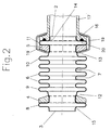
- Fig. 2 shows a metal bellows produced according to the invention with several alternating successive annular bulges 6 and Indentations 7. From FIG. 2 it can be seen that the ring elements 4, 5 1 were positioned on the blank 1 such that after deformation of the blank to the bellows, the ring elements 4, 5 each between two Bulges 8, 9 and 10, 11 in one between these bulges 8, 9 and 10, 11 arranged indentation 12 and 13 come to rest. The ring elements 4, 5 are thus through the bulges 8, 9 or 10, 11 fixed in their position at least so far that they do not have the mentioned bulges can be pushed away.
- the bellows 2 facing the end face and on the ring element 5 adjacent bulge 11 represents the last bulge of the bellows in Direction of the mentioned bellows end 2. It behaves accordingly with the bulge assigned to the opposite bell-end 3 8th.
- the respective last bulge 11 or 8 in the direction of the front bellows end 2 or 3 each represents a complete wave, which means that it merges in the direction of the respective bellows end 2, 3 into a region of an indentation 14 or 15.
- any other form of the last bulge 11 can also be realized.
- the last bulge it is possible for the last bulge to have a different shape than the bulges located between the ring elements.
- the outer diameter of the last bulge can be larger or smaller than the outer diameter of the bulges located between the ring elements, the last bulge can in particular merge into a cylindrical bellows closure via an indentation or it can end with a substantially radially extending wall of the bulge.
- the coupling of a bellows according to FIG. 2 with a counterpart 16 is exemplary shown in the area of the bellows end 2.
- a corresponding Coupling is provided in the area of the opposite bellows end 3. This coupling is - just like in FIGS. 3 and 4 - for the sake of Clarity not shown.
- the counterpart 16 consists of a ring element whose inner diameter corresponds to that of the ring elements 4, 5 and that with a Housing or pipe section 17 is connected.
- the last bulge 11 in the direction of the bellows end 2 is between Ring element 5 and the counterpart 16 arranged, wherein ring element 5th and counterpart 16 by a bracket element 19 towards each other to be pulled, so that ultimately the bulge 11 between the ring element 5 and the counterpart 16 is clamped.
- annular Sealant 20 is provided, which on the bulge 11 is present. This sealant 20 creates a tight connection made between metal bellows and pipe section 17.
- FIG. 3 shows an alternative method for producing a connection to FIG. 2 between a metal bellows and a piece of pipe. Those Parts of FIG. 3 that find a correspondence in FIG. 2 are respectively marked with the same reference numerals.
- FIG. 4 shows a further variant of the invention, elements here also which find their correspondence in FIGS. 2 and 3, with the same reference numerals are designated.
- the metal bellows according to FIG. 4 is also produced in the same way like the metal bellows according to FIGS. 2 and 3. There is only one difference in that after the production of the metal bellows, the last bulge in each case towards a bellows end in the area of their largest diameter is cut off.
- Ring elements 4, 5 and counterparts 16, 21, 23 can also be any other way as shown in FIGS. 2 to 4.
- For example can be used as a flange, support ring for union nuts, ring with external thread or the like. Accordingly, too the connection of ring element 5 and counterpart 16, 21, 23 to others Way as done by means of the bracket 19. In particular, too Screw connections possible.
- the metal bellows can be produced in such a way that the ring elements 4, 5 after the deformation of the blank 1 with its radially inner Form-fitting surfaces, especially clamping in the ring-shaped indentations 12, 13 are present.
- the ring elements 4, 5 with their end faces on the two, the ring elements 4, 5 adjacent bulges 8, 9 and 10, 11th concern, especially pinched between these bulges are.
Abstract
Description
Die Erfindung betrifft ein Verfahren zur Herstellung eines zur Verbindung mit einem Gegenstück geeigneten Metallbalgs, bei dem ein rohrförmiger Rohling durch Kraftbeaufschlagung zu einem Balg mit mehreren alternierend aufeinanderfolgenden ringförmigen Aus- und Einbuchtungen deformiert wird, sowie einen nach einem solchen Verfahren hergestellten Metallbalg.The invention relates to a method for producing a compound with a suitable metal bellows counterpart, in which a tubular Blank by alternating force application to a bellows successive annular bulges and indentations deformed is, as well as a metal bellows produced by such a method.
Metallbälge der angegebenen Art dienen bei Rohrleitungen zur Kompensation von Wärmedehnungen, zur Schalldämpfung, zur Isolation von Rohrvibrationen und zum Ausgleich von Montagetoleranzen. Zu diesen Zwekken werden die Metallbälge üblicherweise mit ihren Stirnseiten mit jeweils einer Rohrleitung verbunden. Durch die Dehn- bzw. Stauchbarkeit der Metallbälge können dann Relativbewegungen der Rohrleitungen zueinander oder unterschiedliche Abstände dieser Rohrleitungen voneinander ausgeglichen werden.Metal bellows of the specified type are used for compensation in pipelines of thermal expansion, for sound absorption, for the isolation of pipe vibrations and to compensate for assembly tolerances. For these purposes the metal bellows are usually with their end faces with each connected to a pipeline. Due to the stretchability or compressibility of the Metal bellows can then relative movements of the pipes to each other or different distances between these pipes be balanced.
Typische Anwendungsbereiche für die Verbindung von Rohrleitungen mittels Metallbälgen sind z. B. die Vakuumtechnik, thermische Solaranlagen zur Brauchwassererwärmung und zur Prozeßwärmeerzeugung, Heizungs- und Warmwasseranlagen, verfahrenstechnische Anlagen, Fernwärmeleitungen, Pipelines und energietechnische Anlagen.Typical areas of application for connecting pipes by means of metal bellows z. B. vacuum technology, thermal solar systems for domestic water heating and process heat generation, heating and hot water systems, process engineering systems, district heating pipes, Pipelines and energy systems.
Um einen Metallbalg mit einer Rohrleitung verbinden zu können, ist es bekannt, ein Ringelement auf einen zylindrischen Endbereich eines Metallbalgs aufzuschieben und den Metallbalg dann in seinen zylindrischen Endbereich zu bördeln. Durch das gebördelte Ende des Metallbalgs wird dann verhindert, daß das Ringelement vom zylindrische Ende des Metallbalgs wieder abgezogen werden kann. Das auf die genannte Weise am Metallbalg fixierte Ringelement kann dann mit einem geeigneten Gegenstück, beispielsweise einem an der Rohrleitung angebrachten Gegenflansch durch Schrauben oder Klemmvorrichtungen verbunden werden.In order to be able to connect a metal bellows to a pipeline, it is known, a ring element on a cylindrical end portion of a metal bellows postpone and then the metal bellows in its cylindrical Flare end area. Through the flared end of the metal bellows then prevents the ring member from the cylindrical end of the metal bellows can be deducted again. That in the manner mentioned on Metal bellows fixed ring element can then with a suitable counterpart, for example a counter flange attached to the pipeline connected by screws or clamps.
Nachteilig an dem beschriebenen Verfahren zur Verbindung von Metallbälgen mit Rohrleitungen ist die Tatsache, daß im Anschluß an die Herstellung des Metallbalgs noch der Verfahrensschritt des Bördelns ausgeführt werden muß, um das Ringelement am Metallbalg zu fixieren. Dieser Verfahrensschritt des Bördelns ist mit wirtschaftlichem Aufwand verbunden, was den Herstellungsprozeß insgesamt auf unerwünschte Weise verteuert.A disadvantage of the described method for connecting metal bellows with piping is the fact that after manufacturing of the metal bellows the crimping process step is carried out must be to fix the ring element on the metal bellows. This Flanging process step is associated with economic effort, which makes the manufacturing process more expensive in an undesirable manner.
Eine Aufgabe der Erfindung besteht darin, ein Verfahren zur Verbindung eines Metallbalgs mit einem Gegenstück zu schaffen, welches mit verringertem Aufwand und insbesondere unter Einsparung des Verfahrensschritts des Bördelns durchgeführt werden kann.An object of the invention is a method of connection to create a metal bellows with a counterpart, which with reduced Effort and, in particular, saving the procedural step of flanging can be carried out.
Diese Aufgabe wird erfindungsgemäß dadurch gelöst, daß zumindest ein zur Verbindung mit dem Gegenstück dienendes Ringelement relativ zum Rohling derart angeordnet wird, daß es diesen umgibt, und daß anschließend die Deformation des Rohlings zum Balg derart erfolgt, daß das Ringelement in einer ringförmigen Einbuchtung zwischen zwei benachbarten Ausbuchtungen zu liegen kommt. This object is achieved in that at least one for connection to the counterpart serving ring element relative to Blank is arranged so that it surrounds it, and then the deformation of the blank to the bellows takes place in such a way that the ring element in an annular indentation between two neighboring ones Bulges come to rest.
Erfindungsgemäß wird also das Ringelement bereits vor Herstellung des Metallbalgs auf den Rohling aufgeschoben, woraufhin dann der den Balg erzeugende Deformationsprozeß beginnt. Das Ringelement wird während des Deformationsprozesses so positioniert, daß es letztlich, nach vollendeter Herstellung des Balgs, zwischen zwei benachbarten Ausbuchtungen zu liegen kommt und durch diese beiden Ausbuchtungen zumindest innerhalb bestimmter Grenzen fixiert ist. Die Fixierung des Ringelements wird dadurch sichergestellt, daß der Innendurchmesser des Ringelements kleiner ist als der Außendurchmesser des Balgs im Bereich einer Ausbuchtung. Durch diese Abmessungen wird gewährleistet, daß sich das Ringelement nicht über eine Ausbuchtung des Balgs hinweg bewegen kann.According to the invention, the ring element is already before the manufacture of Metal bellows pushed onto the blank, whereupon the bellows generating deformation process begins. The ring element is used during of the deformation process so that it ultimately, after completion Production of the bellows between two neighboring bulges comes to rest and at least within these two bulges certain limits is fixed. The fixation of the ring element is ensured by the fact that the inner diameter of the ring element is smaller than the outer diameter of the bellows in the region of a bulge. These dimensions ensure that the Do not move the ring element over a bulge of the bellows can.
Durch die erfindungsgemäße Einsparung des Bördelns wird erreicht, daß ein Metallbalg mit einem an ihm fixierten Ringelement in einem einzigen Verfahrensschritt, nämlich durch die Deformation des Rohlings zum Balg hergestellt werden kann, was erhebliche wirtschaftliche Vorteile mit sich bringt.The saving of flanging according to the invention ensures that a metal bellows with a ring element fixed to it in one Process step, namely by the deformation of the blank to the bellows can be manufactured, which has significant economic benefits brings.
Bevorzugte Ausführungsformen des erfindungsgemäßen Verfahrens sind
in den Unteransprüchen 1 bis 14 beschrieben.Preferred embodiments of the method according to the invention are
described in
Bevorzugte Ausführungsformen eines erfindungsgemäßen Metallbalgs gemäß
Anspruch 15 sind in den Ansprüchen 16 und 17 beschrieben.Preferred embodiments of a metal bellows according to the
Die Erfindung wird nachfolgend anhand von Ausführungsbeispielen unter Bezugnahme auf die Zeichnungen beschrieben; in diesen zeigen:
- Fig. 1
- einen Rohling mit zwei aufgeschobenen Ringelementen,
- Fig. 2
- eine nach einer ersten Variante des erfindungsgemäßen Verfahrens hergestellte Metallbalg-Rohrverbindung,
- Fig. 3
- eine nach der zweiten Variante des erfindungsgemäßen Verfahrens hergestellte Metallbalg-Rohrverbindung, und
- Fig. 4
- eine nach der dritten Variante des erfindungsgemäßen Verfahrens hergestellte Metallbalg-Rohrverbindung.
- Fig. 1
- a blank with two ring elements pushed on,
- Fig. 2
- a metal bellows pipe connection produced according to a first variant of the method according to the invention,
- Fig. 3
- a metal bellows pipe connection produced according to the second variant of the method according to the invention, and
- Fig. 4
- a metal bellows pipe connection produced according to the third variant of the method according to the invention.
Fig. 1 zeigt einen Rohling 1, welcher die Form eines zylindrischen Rohrs aufweist. Alternativ kann der Rohling 1 umlaufende Sicken aufweisen, die im Bereich der auszuformenden Einbuchtungen liegen, um auf diese Weise bei der nachfolgenden Deformation größere Durchmesserdifferenzen zwischen Ein- und Ausbuchtungen erzeugen zu können.Fig. 1 shows a blank 1, which has the shape of a cylindrical tube having. Alternatively, the blank 1 can have circumferential beads that in the area of the indentations to be formed, in this way with the subsequent deformation larger diameter differences between indentations and bulges.
Über die beiden stirnseitigen Endbereiche 2, 3 des Rohlings 1 ist jeweils
ein Ringelement 4, 5 geschoben. Beide Ringelemente 4, 5 weisen jeweils
den gleichen Abstand zum zugeordneten stirnseitigen Ende 3, 2 des Rohlings
1 auf. Der Innendurchmesser der Ringelemente 4, 5 entspricht im
wesentlichen dem Außendurchmesser des Rohlings 1, ist jedoch so groß,
daß die Ringelemente 4, 5 ohne großen Kraftaufwand auf den Rohling 1
aufgeschoben werden können.About the two
Der Rohling 1 mit den Ringelementen 4, 5 wird anschließend in eine geeignete
Form eingebracht, in der die Deformation des Rohlings 1 zum Balg
erfolgt. Der genannte Deformationsprozeß kann dadurch erfolgen, daß im
Inneren des Rohlings 1 radial nach außen gerichtete Druckkräfte erzeugt
werden, denen zumindest im Bereich der auszuformenden Balgeinbuchtungen
radial nach innen gerichtete, durch die genannte Form bewirkte
Stützkräfte entgegenwirken. Durch die Deformation des Rohlings 1 zum
Balg erfolgt naturgemäß eine Verkürzung des Rohlings 1 bzw. des Balgs,
da für die Ausformung der Balg-Ausbuchtungen die Wand des Rohlings 1
in den entsprechenden Bereichen nach außen gedrückt werden muß, was
dann zwangsläufig ein axiales Zusammenziehen bzw. eine Verkürzung des
Rohlings 1 bewirkt. Diese Verkürzung ist an den in den Fig. 2 bis 4 dargestellten
Metallbälgen erkennbar. Um beim Deformationsvorgang der genannten
Verkürzung Rechnung zu tragen, muß die Form, welche die radial
nach innen gerichteten Stützkräfte bewirkt, sich ebenfalls verkürzen
bzw. zusammenziehen. Solche Formen sind aus dem Stand der Technik
bekannt.The blank 1 with the
Beim Deformationsvorgang des Rohlings 1 zum Balg bewirkten nicht nur
die genannte Form, sondern ebenfalls die beiden Ringelemente 4, 5 radial
nach innen gerichtete Stützkräfte. Dies bedeutet, daß sich der Rohling
während des Deformationsprozesses im Bereich der Ringelemente 4, 5 nur
soweit ausdehnen kann, bis er am Innenumfang der Ringelemente 4, 5
anliegt.During the deformation process of the blank 1 to the bellows not only caused
said shape, but also the two
Um den Deformationsvorgang ausführen zu können, werden entweder zuerst
die Ringelemente 4, 5 über den Rohling 1 geschoben und anschließend
der Rohling 1 mit den Ringelementen 4, 5 in die - in Fig. 1 nicht dargestellte
- Form eingelegt. Ebenso ist es jedoch auch möglich, zuerst die
Ringelemente 4, 5 in die Form einzulegen und anschließend den Rohling 1
durch die Ringelemente 4, 5 hindurch in die Form einzuschieben. To be able to carry out the deformation process, either first
the
Fig. 2 zeigt einen erfindungsgemäß hergestellten Metallbalg mit mehreren
alternierend aufeinanderfolgenden ringförmigen Ausbuchtungen 6 und
Einbuchtungen 7. Aus Fig. 2 ist ersichtlich, daß die Ringelemente 4, 5
gemäß Fig. 1 derart am Rohling 1 positioniert wurden, daß nach Deformation
des Rohlings zum Balg die Ringelemente 4, 5 jeweils zwischen zwei
Ausbuchtungen 8, 9 bzw. 10, 11 in einer zwischen diesen Ausbuchtungen
8, 9 bzw. 10, 11 angeordneten Einbuchtung 12 bzw. 13 zu liegen kommen.
Die Ringelemente 4, 5 sind somit durch die Ausbuchtungen 8, 9
bzw. 10, 11 in ihrer Lage zumindest soweit fixiert, daß sie nicht über die
genannten Ausbuchtungen hinweg geschoben werden können.Fig. 2 shows a metal bellows produced according to the invention with several
alternating successive
Die dem stirnseitigen Balgende 2 zugewandte und an das Ringelement 5
angrenzende Ausbuchtung 11 stellt die letzte Ausbuchtung des Balgs in
Richtung des genannten Balgendes 2 dar. Entsprechend verhält es sich
mit der dem gegenüberliegenden Balgende 3 zugeordneten Ausbuchtung
8.The
Die jeweils letzte Ausbuchtung 11 bzw. 8 in Richtung des stirnseitigen
Balgendes 2 bzw. 3 stellt jeweils eine vollständige Welle dar, was bedeutet,
daß sie in Richtung des jeweiligen Balgendes 2, 3 in einen Bereich einer
Einbuchtung 14 bzw. 15 übergeht.
Es sind jedoch auch beliebige andere Ausformungen der letzten Ausbuchtung
11 realisierbar. Insbesondere ist es möglich, daß die letzte Ausbuchtung
eine andere Form aufweist als die zwischen den Ringelementen
gelegenen Ausbuchtungen. Zum Beispiel kann der Außendurchmesser der
letzten Ausbuchtung größer oder kleiner sein als der Außendurchmesser
der zwischen den Ringelementen gelegenen Ausbuchtungen, die letzte
Ausbuchtung kann insbesondere über eine Einbuchtung in einen zylindrischen
Balgabschluß übergehen oder sie kann mit einer im wesentlichen
radial verlaufenden Wand der Ausbuchtung enden.The respective
However, any other form of the
Die Kopplung eines Balgs gemäß Fig. 2 mit einem Gegenstück 16 ist exemplarisch
im Bereich des Balgendes 2 dargestellt. Eine entsprechende
Kopplung ist im Bereich des gegenüberliegenden Balgendes 3 vorgesehen.
Diese Kopplung ist - ebenso wie bei den Fig. 3 und 4 - aus Gründen der
Übersichtlichkeit jedoch nicht dargestellt.The coupling of a bellows according to FIG. 2 with a
Das Gegenstück 16 besteht aus einem Ringelement, dessen Innendurchmesser
demjenigen der Ringelemente 4, 5 entspricht und das mit einem
Gehäuse oder Rohrstück 17 verbunden ist.The
Die in Richtung des Balgendes 2 letzte Ausbuchtung 11 ist zwischen dern
Ringelement 5 und dem Gegenstück 16 angeordnet, wobei Ringelement 5
und Gegenstück 16 durch ein Klammerelement 19 in Richtung aufeinander
zu gezogen werden, so daß letztlich die Ausbuchtung 11 zwischen
dem Ringelement 5 und dem Gegenstück 16 eingeklemmt ist.The
Bevorzugt ist es, wenn das Gegenstück 16 mit einem umlaufenden, ringförmigen
Dichtungsmittel 20 versehen ist, welches an der Ausbuchtung
11 anliegt. Durch dieses Dichtungsmittel 20 wird eine dichte Verbindung
zwischen Metallbalg und Rohrstück 17 hergestellt.It is preferred if the
Fig. 3 zeigt ein zu Fig. 2 alternatives Verfahren zur Herstellung einer Verbindung zwischen einem Metallbalg und einem Rohrstück. Diejenigen Teile der Fig. 3, welche eine Entsprechung in der Fig. 2 finden, sind jeweils mit den gleichen Bezugszeichen gekennzeichnet.FIG. 3 shows an alternative method for producing a connection to FIG. 2 between a metal bellows and a piece of pipe. Those Parts of FIG. 3 that find a correspondence in FIG. 2 are respectively marked with the same reference numerals.
Der Metallbalg gemäß Fig. 3 wird auf exakt die gleiche Weise hergestellt
wie der Metallbalg gemäß Fig. 2. Ein Unterschied besteht dann lediglich
im Vorgang des Verbindens des Metallbalgs mit dem Rohrstück 17. Dabei
werden nämlich Ringelement 5 und Gegenstück 21 so stark zueinander
gezogen, daß die zwischen Ringelement 5 und Gegenstück 21 liegende
Ausbuchtung 11 deformiert wird. Diese Deformation ist dabei so stark,
daß sich die beiden, sich radial erstreckenden Wände der Ausbuchtung 11
in dem der Balgachse zugewandten Bereich der Ausbuchtung 11 gegenseitig
berühren.3 is produced in exactly the same way
like the metal bellows according to FIG. 2. There is only one difference
in the process of connecting the metal bellows to the
Eine weitere Möglichkeit besteht darin, die letzte Ausbuchtung 11 des
Metallbalgs bereits während der Balgherstellung so zu deformieren, daß
sich die im wesentlichen radial verlaufenden Wände in dem der Balgachse
zugewandten Bereich gegenseitig berühren.Another possibility is the
Um zu vermeiden, daß die Ausbuchtung 11 in ihrem der Balgachse abgewandten
Ende durch die genannte Deformation bricht, ist das Gegenstück
21 mit einer Phase 22 versehen, die bewirkt, daß in dem genannten Bereich
der Ausbuchtung 11 keine Klemmung zwischen Ringelement 5 und
Gegenstück 21 auftritt.In order to avoid that the
Durch die Deformation der Ausbuchtung 11 wird eine unerwünschte Federwirkung
zwischen Ringelement 5 und Gegenstück 21 vermieden. The deformation of the
Fig. 4 zeigt eine weitere Variante der Erfindung, wobei auch hier Elemente, die ihre Entsprechung in den Fig. 2 bzw. 3 finden, mit denselben Bezugszeichen bezeichnet sind.FIG. 4 shows a further variant of the invention, elements here also which find their correspondence in FIGS. 2 and 3, with the same reference numerals are designated.
Auch der Metallbalg gemäß Fig. 4 wird in der gleichen Weise hergestellt wie die Metallbälge gemäß den Fig. 2 und 3. Ein Unterschied besteht lediglich darin, daß nach Herstellung des Metallbalgs die jeweils letzte Ausbuchtung in Richtung eines stirnseitigen Balgendes im Bereich ihres größten Durchmessers abgeschnitten wird.The metal bellows according to FIG. 4 is also produced in the same way like the metal bellows according to FIGS. 2 and 3. There is only one difference in that after the production of the metal bellows, the last bulge in each case towards a bellows end in the area of their largest diameter is cut off.
Ringelemente 4, 5 und Gegenstücke 16, 21, 23 können auch beliebig anders
als in Fig. 2 bis 4 dargestellt ausgestaltet werden. Beispielsweise
können sie als Flansch, Stützring für Überwurfmuttern, Ring mit Außengewinde
oder dergleichen ausgebildet sein. Dementsprechend kann auch
die Verbindung von Ringelement 5 und Gegenstück 16, 21, 23 auf andere
Weise als mittels der Klammer 19 erfolgen. Insbesondere sind auch
Schraubverbindungen möglich.
Die Erzeugung des Metallbalgs kann derart erfolgen, daß die Ringelemente
4, 5 nach der Deformation des Rohlings 1 mit ihren radial innen liegenden
Flächen formschlüssig, insbesondere klemmend in den ringförmigen Einbuchtungen
12, 13 anliegen. Alternativ oder zusätzlich ist es jedoch auch
möglich, daß die Ringelemente 4, 5 mit ihren Stirnflächen an den beiden,
den Ringelementen 4, 5 benachbarten Ausbuchtungen 8, 9 bzw. 10, 11
anliegen, insbesondere zwischen diesen Ausbuchtungen eingeklemmt
sind. The metal bellows can be produced in such a way that the
Schließlich ist es auch möglich, die Balgherstellung derart zu gestalten,
daß die Ringelemente 4, 5 nach der Deformation des Rohlings 1 im Bereich
der ringförmigen Einbuchtungen 12, 13 bezogen auf die Längsachse
des Balgs axial verschiebbar und/oder drehbar sind.Finally, it is also possible to design the bellows production in such a way
that the
Claims (10)
dadurch gekennzeichnet,
characterized,
dadurch gekennzeichnet,
characterized,
dadurch gekennzeichnet,
daß die einem stirnseitigen Balgende (2, 3) zugewandte und an das Ringelement (4, 5) angrenzende Ausbuchtung (8, 11) die letzte Ausbuchtung des Balgs in Richtung des stirnseitigen Balgendes (3, 2) ist und das stirnseitige Balgende (3, 2) durch einen Bereich einer Einbuchtung (14, 15) und/oder durch einen zylindrischen Balgabschluß gebildet ist, wobei insbesondere die in Richtung des stirnseitigen Balgendes (2, 3) gelegene letzte Ausbuchtung (8, 11) zwischen dem Ringelement (4, 5) und dem Gegenstück (16, 21, 23) aufnehmbar ist.Method according to one of the preceding claims,
characterized,
that the bulge (8, 11) facing an end bellows (2, 3) and adjoining the ring element (4, 5) is the last bulge of the bellows in the direction of the end bellows (3, 2) and the end bellows (3, 2) is formed by a region of an indentation (14, 15) and / or by a cylindrical bellows closure, the last bulge (8, 11) between the ring element (4, 5) located in the direction of the end face of the bellows (2, 3) in particular ) and the counterpart (16, 21, 23) is receivable.
dadurch gekennzeichnet,
daß nach Herstellung des Balgs die zwischen dem Ringelement (4, 5) und dem Gegenstück (16, 21, 23) aufnehmbare Ausbuchtung (8, 11) bei Verbindung von Ringelement (4, 5) und Gegenstück (16, 21, 23) in Axialrichtung des Balgs deformierbar und zwischen Ringelement (4, 5) und Gegenstück (16, 21, 23) klemmbar ist, oder daß während Herstellung des Balgs die zwischen dem Ringelement (4, 5) und dem Gegenstück (16, 21, 23) aufnehmbare Ausbuchtung (8, 11) insbesondere durch bewegliche Elemente der Form in Axialrichtung des Balgs deformiert, vorzugsweise zusammengedrückt wird.Method according to claim 5,
characterized,
that after manufacture of the bellows between the ring element (4, 5) and the counterpart (16, 21, 23) receptacle bulge (8, 11) when connecting the ring element (4, 5) and counterpart (16, 21, 23) in Axial direction of the bellows deformable and clampable between the ring element (4, 5) and counterpart (16, 21, 23), or that during the production of the bellows between the ring element (4, 5) and the counterpart (16, 21, 23) receivable Bulge (8, 11) is deformed in particular by movable elements of the shape in the axial direction of the bellows, preferably compressed.
dadurch gekennzeichnet,
daß die Deformation hauptsächlich in dem der Balgachse zugewandten Bereich der Ausbuchtung (8, 11) erfolgt, wobei insbesondere die Deformation derart erfolgt, daß sich die beiden, sich im wesentlichen radial erstreckenden Wände der Ausbuchtung (8, 11) in dem der Balgachse zugewandten Bereich der Ausbuchtung (8, 11) berühren.Method according to claim 4,
characterized,
that the deformation occurs mainly in the region of the bulge (8, 11) facing the bellows axis, the deformation taking place in particular in such a way that the two essentially radially extending walls of the bulge (8, 11) extend in the region facing the bellows axis touch the bulge (8, 11).
dadurch gekennzeichnet,
daß der Balg nach der Ausformung der Ein- und Ausbuchtungen (6, 7) im Bereich seiner in Richtung des stirnseitigen Balgendes (2, 3) gelegenen letzten Ausbuchtung (8, 11) abgeschnitten wird.Process according to claims 1 to 3,
characterized,
that the bellows is cut off after the indentations and bulges (6, 7) have been formed in the region of its last bulge (8, 11) located in the direction of the end face of the bellows (2, 3).
dadurch gekennzeichnet,
daß Ringelement (4, 5) und Form derart bemessen sind, daß das Ringelement (4, 5) nach der Deformation des Rohlings (1) mit seiner radial innen liegenden Fläche formschlüssig, insbesondere klemmend, an der ringförmigen Einbuchtung (12, 13) anliegt, und/oder daß Ringelement (4, 5) und Form derart bemessen sind, daß das Ringelement (4,5) nach der Deformation des Rohlings (1) mit seinen Stirnflächen an den beiden, dem Ringelement (4, 5) benachbarten Ausbuchtungen (8, 9; 10, 11) anliegt, insbesondere zwischen den beiden Ausbuchtungen (8, 9; 10, 11) eingeklemmt ist.Method according to one of the preceding claims,
characterized,
that the ring element (4, 5) and shape are dimensioned such that after the deformation of the blank (1) the ring element (4, 5) lies with its radially inner surface in a form-fitting, in particular clamping manner, against the ring-shaped indentation (12, 13) , and / or that the ring element (4, 5) and shape are dimensioned such that after the deformation of the blank (1) the ring element (4, 5) has its end faces on the two bulges (4, 5) adjacent to the ring element (4, 5) 8, 9; 10, 11), in particular between the two bulges (8, 9; 10, 11) is clamped.
dadurch gekennzeichnet,
daß Ringelement (4, 5) und Form derart bemessen sind, daß das Ringelement (4, 5) nach der Deformation des Rohlings (1) im Bereich der ringförmigen Einbuchtung (12, 13) bezogen auf die Längsachse des Balgs axial verschiebbar und/oder drehbar ist, und/oder daß zwei Ringelemente (4, 5) relativ zum Rohling (1) derart angeordnet werden, daß sie diesen insbesondere in seinen beiden einander gegenüberliegenden Endbereichen umgeben.Method according to one of the preceding claims,
characterized,
that the ring element (4, 5) and shape are dimensioned such that the ring element (4, 5) after the deformation of the blank (1) in the region of the annular indentation (12, 13) with respect to the longitudinal axis of the bellows axially displaceable and / or is rotatable, and / or that two ring elements (4, 5) are arranged relative to the blank (1) in such a way that they surround the latter in particular in its two opposite end regions.
dadurch gekennzeichnet,
daß das Ringelement bzw. die Ringelemente (4, 5) und/oder das Gegenstück bzw. die Gegenstücke (16, 21, 23) ein ebenfalls ringförmiges Dichtungsmittel (20) aufweisen, und/oder daß das Ringelement bzw. die Ringelemente (4, 5) als Flansch, Stützring für Überwurfmuttern, Ring mit Außengewinde oder dgl. ausgebildet sind.Metal bellows according to claim 9,
characterized,
that the ring element or the ring elements (4, 5) and / or the counterpart or the counterparts (16, 21, 23) also have an annular sealing means (20), and / or that the ring element or the ring elements (4, 5) are designed as a flange, support ring for union nuts, ring with external thread or the like.
Applications Claiming Priority (2)
| Application Number | Priority Date | Filing Date | Title |
|---|---|---|---|
| DE19806304 | 1998-02-16 | ||
| DE1998106304 DE19806304A1 (en) | 1998-02-16 | 1998-02-16 | Bellows and bellows manufacturing process |
Publications (2)
| Publication Number | Publication Date |
|---|---|
| EP0936392A2 true EP0936392A2 (en) | 1999-08-18 |
| EP0936392A3 EP0936392A3 (en) | 2001-02-14 |
Family
ID=7857859
Family Applications (1)
| Application Number | Title | Priority Date | Filing Date |
|---|---|---|---|
| EP99103002A Withdrawn EP0936392A3 (en) | 1998-02-16 | 1999-02-15 | Metal bellows and its method of manufacture |
Country Status (2)
| Country | Link |
|---|---|
| EP (1) | EP0936392A3 (en) |
| DE (1) | DE19806304A1 (en) |
Cited By (5)
| Publication number | Priority date | Publication date | Assignee | Title |
|---|---|---|---|---|
| DE102005024413A1 (en) * | 2005-05-27 | 2006-12-07 | Airbus Deutschland Gmbh | Connecting piece for the articulated connection of a first and a second pipeline |
| DE102008021326A1 (en) | 2007-05-18 | 2008-11-20 | Scania Cv Ab | Flexible tube coupling has tubular element made of flexible material and rigid tubular flange element, which has connecting surface, and flexible tubular element and flange element are arranged together |
| DE102014112559A1 (en) | 2014-09-01 | 2016-03-03 | Christian Becker | Conduction element of a supply line of an internal combustion engine of a motor vehicle and method for producing such a line element |
| CN111536356A (en) * | 2020-04-28 | 2020-08-14 | 江苏赛尔超高压特种管业有限公司 | Novel glass fiber reinforced thermoplastic plastic pipe and production process thereof |
| CN111720639A (en) * | 2020-06-02 | 2020-09-29 | 台州市涌星贸易有限公司 | High withstand voltage PFA bellows |
Families Citing this family (2)
| Publication number | Priority date | Publication date | Assignee | Title |
|---|---|---|---|---|
| DE10065573A1 (en) * | 2000-12-28 | 2002-07-04 | Brugg Rohrsysteme Gmbh | Flanging of the end of helically corrugated pipe using pipe-flaring tool has de-corrugating trough region by moving pressure part rotating about axis of tool, bending de-corrugated region and peak region to form flange |
| CN107088599A (en) * | 2017-05-06 | 2017-08-25 | 芜湖瑞德机械科技有限公司 | A kind of stainless steel tube makes ripple machine |
Citations (7)
| Publication number | Priority date | Publication date | Assignee | Title |
|---|---|---|---|---|
| US1870904A (en) * | 1930-08-02 | 1932-08-09 | Fulton Sylphon Co | Attachment of heads to bellows |
| US2196676A (en) * | 1937-09-23 | 1940-04-09 | Chicago Metal Hose Corp | Flexible connector |
| US2818636A (en) * | 1949-05-26 | 1958-01-07 | Chicago Metal Hose Corp | Method of manufacturing reinforced flexible conduit |
| US2965961A (en) * | 1948-02-13 | 1960-12-27 | Flexonics Corp | Method of making a reinforced flexible conduit assembly |
| FR2672373A1 (en) * | 1991-01-31 | 1992-08-07 | Hubschen Alfred | Improvements in the production of connection elements used in installations for creating a vacuum |
| EP0557594A1 (en) * | 1992-02-24 | 1993-09-01 | Witzenmann GmbH Metallschlauch-Fabrik Pforzheim | Method for mounting a connection element |
| DE9420502U1 (en) * | 1994-11-30 | 1995-07-20 | Witzenmann Metallschlauchfab | Connection between a pipe and a tubular line element |
Family Cites Families (8)
| Publication number | Priority date | Publication date | Assignee | Title |
|---|---|---|---|---|
| US1366473A (en) * | 1914-04-22 | 1921-01-25 | Harry C Mallory | Expansible and collapsible element for thermostatic and pressuresensitive devices |
| US1656213A (en) * | 1920-08-31 | 1928-01-17 | American Radiator Co | Method of producing expansible-collapsible elements |
| US1727281A (en) * | 1921-10-17 | 1929-09-03 | Fulton Sylphon Co | Method of making flexible corrugated tubular walls |
| US2014355A (en) * | 1933-02-27 | 1935-09-10 | United States Gypsum Co | Vibration isolating pipe connection |
| US2832613A (en) * | 1954-06-10 | 1958-04-29 | Flexonics Corp | Autogenous welded laminated expansion joint for conduits |
| DE7030864U (en) * | 1970-08-18 | 1970-12-17 | Eiff Ulrich Christof Von | CONNECTION FOR ONE LINE |
| DE9209274U1 (en) * | 1992-02-24 | 1992-10-08 | Witzenmann Gmbh, Metallschlauch-Fabrik Pforzheim, 7530 Pforzheim, De | |
| DE29606683U1 (en) * | 1996-04-12 | 1997-08-14 | Witzenmann Metallschlauchfab | Connection between a component and a tubular line element |
-
1998
- 1998-02-16 DE DE1998106304 patent/DE19806304A1/en not_active Ceased
-
1999
- 1999-02-15 EP EP99103002A patent/EP0936392A3/en not_active Withdrawn
Patent Citations (7)
| Publication number | Priority date | Publication date | Assignee | Title |
|---|---|---|---|---|
| US1870904A (en) * | 1930-08-02 | 1932-08-09 | Fulton Sylphon Co | Attachment of heads to bellows |
| US2196676A (en) * | 1937-09-23 | 1940-04-09 | Chicago Metal Hose Corp | Flexible connector |
| US2965961A (en) * | 1948-02-13 | 1960-12-27 | Flexonics Corp | Method of making a reinforced flexible conduit assembly |
| US2818636A (en) * | 1949-05-26 | 1958-01-07 | Chicago Metal Hose Corp | Method of manufacturing reinforced flexible conduit |
| FR2672373A1 (en) * | 1991-01-31 | 1992-08-07 | Hubschen Alfred | Improvements in the production of connection elements used in installations for creating a vacuum |
| EP0557594A1 (en) * | 1992-02-24 | 1993-09-01 | Witzenmann GmbH Metallschlauch-Fabrik Pforzheim | Method for mounting a connection element |
| DE9420502U1 (en) * | 1994-11-30 | 1995-07-20 | Witzenmann Metallschlauchfab | Connection between a pipe and a tubular line element |
Cited By (7)
| Publication number | Priority date | Publication date | Assignee | Title |
|---|---|---|---|---|
| DE102005024413A1 (en) * | 2005-05-27 | 2006-12-07 | Airbus Deutschland Gmbh | Connecting piece for the articulated connection of a first and a second pipeline |
| US7677606B2 (en) | 2005-05-27 | 2010-03-16 | Airbus Deutschland Gmbh | Connector for an articulated connection of a first and second pipeline |
| DE102005024413B4 (en) * | 2005-05-27 | 2011-01-27 | Airbus Operations Gmbh | Connecting piece for the articulated connection of a first and a second pipeline |
| DE102008021326A1 (en) | 2007-05-18 | 2008-11-20 | Scania Cv Ab | Flexible tube coupling has tubular element made of flexible material and rigid tubular flange element, which has connecting surface, and flexible tubular element and flange element are arranged together |
| DE102014112559A1 (en) | 2014-09-01 | 2016-03-03 | Christian Becker | Conduction element of a supply line of an internal combustion engine of a motor vehicle and method for producing such a line element |
| CN111536356A (en) * | 2020-04-28 | 2020-08-14 | 江苏赛尔超高压特种管业有限公司 | Novel glass fiber reinforced thermoplastic plastic pipe and production process thereof |
| CN111720639A (en) * | 2020-06-02 | 2020-09-29 | 台州市涌星贸易有限公司 | High withstand voltage PFA bellows |
Also Published As
| Publication number | Publication date |
|---|---|
| DE19806304A1 (en) | 1999-08-19 |
| EP0936392A3 (en) | 2001-02-14 |
Similar Documents
| Publication | Publication Date | Title |
|---|---|---|
| EP1707861B1 (en) | Fitting and method for manufacturing thereof | |
| EP0589413B1 (en) | Pipe end fitting | |
| DE3317061A1 (en) | FLANGE JOINT ARRANGEMENT | |
| EP1907742B1 (en) | Flexible hose and method for mounting a coupling nut on a flexible hose | |
| DE19520099C2 (en) | Pipe connection and process for its manufacture | |
| EP0936392A2 (en) | Metal bellows and its method of manufacture | |
| DE10248986A1 (en) | Pipe joint assembly has annular claw which extends outwardly from joint block and crimped over flange in each pipe so that engaging recesses of joining block are engaged with flange of each pipe | |
| EP3135976A1 (en) | Connection assembly for corrugated pipe hose lines | |
| DE19757946C2 (en) | pipe connection | |
| EP2295842B1 (en) | Pipe connector for sealed connection to an end of a tube made of resilient material | |
| EP2510271B1 (en) | Crimping connection for tubes and method of production of a tube connection with such a crimping connection | |
| EP0824383A1 (en) | Process and pressing tools for joining tubular elements | |
| DE19815244A1 (en) | Hollow metal body forming method for hydraulic fluid line connections, such as for automobile hydraulics | |
| DE2610297C3 (en) | Process for the production of a permanent connection between corrugated metal pipes | |
| DE102012003146B4 (en) | Hose connection and method for making a hose connection | |
| EP0683345B1 (en) | Device for connecting pipes for motor vehicle exhaust systems | |
| DE3029621A1 (en) | FORM AND GROOVE DEVICE FOR PIPE END | |
| EP2851533B1 (en) | Flexible pipe element | |
| DE19526085A1 (en) | Jointed connection of two pipes of exhaust gas system | |
| WO1997043572A1 (en) | Hose union and process for its production | |
| WO1999011964A1 (en) | Tubing piece and a method for the production thereof | |
| DE3741646A1 (en) | Hose connection | |
| DE3418307A1 (en) | Method for the production of a thin-walled shell in the shape of an annular channel and an apparatus for carrying out the method | |
| EP1483521B1 (en) | Pipe connection | |
| CH695026A5 (en) | Pipe connection device for producing pressure-tight pipe connections has a socket-shaped main unit to rotate symmetrically with the ends of pieces of piping |
Legal Events
| Date | Code | Title | Description |
|---|---|---|---|
| PUAI | Public reference made under article 153(3) epc to a published international application that has entered the european phase |
Free format text: ORIGINAL CODE: 0009012 |
|
| AK | Designated contracting states |
Kind code of ref document: A2 Designated state(s): AT BE CH CY DE DK ES FI FR GB GR IE IT LI LU MC NL PT SE |
|
| AX | Request for extension of the european patent |
Free format text: AL;LT;LV;MK;RO;SI |
|
| PUAL | Search report despatched |
Free format text: ORIGINAL CODE: 0009013 |
|
| AK | Designated contracting states |
Kind code of ref document: A3 Designated state(s): AT BE CH CY DE DK ES FI FR GB GR IE IT LI LU MC NL PT SE |
|
| AX | Request for extension of the european patent |
Free format text: AL;LT;LV;MK;RO;SI |
|
| RIC1 | Information provided on ipc code assigned before grant |
Free format text: 7F 16L 27/11 A, 7F 16L 51/02 B, 7B 21D 15/06 B, 7F 16L 25/00 B |
|
| AKX | Designation fees paid | ||
| PUAJ | Public notification under rule 129 epc |
Free format text: ORIGINAL CODE: 0009425 |
|
| REG | Reference to a national code |
Ref country code: DE Ref legal event code: 8566 |
|
| PUAJ | Public notification under rule 129 epc |
Free format text: ORIGINAL CODE: 0009425 |
|
| STAA | Information on the status of an ep patent application or granted ep patent |
Free format text: STATUS: THE APPLICATION IS DEEMED TO BE WITHDRAWN |
|
| 18D | Application deemed to be withdrawn |
Effective date: 20010815 |