EP0936156B1 - Container closure - Google Patents
Container closure Download PDFInfo
- Publication number
- EP0936156B1 EP0936156B1 EP99102481A EP99102481A EP0936156B1 EP 0936156 B1 EP0936156 B1 EP 0936156B1 EP 99102481 A EP99102481 A EP 99102481A EP 99102481 A EP99102481 A EP 99102481A EP 0936156 B1 EP0936156 B1 EP 0936156B1
- Authority
- EP
- European Patent Office
- Prior art keywords
- section
- closure
- main body
- pinch
- spout
- Prior art date
- Legal status (The legal status is an assumption and is not a legal conclusion. Google has not performed a legal analysis and makes no representation as to the accuracy of the status listed.)
- Expired - Lifetime
Links
Images


Classifications
-
- B—PERFORMING OPERATIONS; TRANSPORTING
- B65—CONVEYING; PACKING; STORING; HANDLING THIN OR FILAMENTARY MATERIAL
- B65D—CONTAINERS FOR STORAGE OR TRANSPORT OF ARTICLES OR MATERIALS, e.g. BAGS, BARRELS, BOTTLES, BOXES, CANS, CARTONS, CRATES, DRUMS, JARS, TANKS, HOPPERS, FORWARDING CONTAINERS; ACCESSORIES, CLOSURES, OR FITTINGS THEREFOR; PACKAGING ELEMENTS; PACKAGES
- B65D75/00—Packages comprising articles or materials partially or wholly enclosed in strips, sheets, blanks, tubes, or webs of flexible sheet material, e.g. in folded wrappers
- B65D75/52—Details
- B65D75/58—Opening or contents-removing devices added or incorporated during package manufacture
- B65D75/5861—Spouts
- B65D75/5872—Non-integral spouts
- B65D75/5883—Non-integral spouts connected to the package at the sealed junction of two package walls
-
- B—PERFORMING OPERATIONS; TRANSPORTING
- B65—CONVEYING; PACKING; STORING; HANDLING THIN OR FILAMENTARY MATERIAL
- B65D—CONTAINERS FOR STORAGE OR TRANSPORT OF ARTICLES OR MATERIALS, e.g. BAGS, BARRELS, BOTTLES, BOXES, CANS, CARTONS, CRATES, DRUMS, JARS, TANKS, HOPPERS, FORWARDING CONTAINERS; ACCESSORIES, CLOSURES, OR FITTINGS THEREFOR; PACKAGING ELEMENTS; PACKAGES
- B65D47/00—Closures with filling and discharging, or with discharging, devices
- B65D47/04—Closures with discharging devices other than pumps
- B65D47/06—Closures with discharging devices other than pumps with pouring spouts or tubes; with discharge nozzles or passages
- B65D47/10—Closures with discharging devices other than pumps with pouring spouts or tubes; with discharge nozzles or passages having frangible closures
-
- B—PERFORMING OPERATIONS; TRANSPORTING
- B65—CONVEYING; PACKING; STORING; HANDLING THIN OR FILAMENTARY MATERIAL
- B65D—CONTAINERS FOR STORAGE OR TRANSPORT OF ARTICLES OR MATERIALS, e.g. BAGS, BARRELS, BOTTLES, BOXES, CANS, CARTONS, CRATES, DRUMS, JARS, TANKS, HOPPERS, FORWARDING CONTAINERS; ACCESSORIES, CLOSURES, OR FITTINGS THEREFOR; PACKAGING ELEMENTS; PACKAGES
- B65D2401/00—Tamper-indicating means
- B65D2401/15—Tearable part of the closure
-
- B—PERFORMING OPERATIONS; TRANSPORTING
- B65—CONVEYING; PACKING; STORING; HANDLING THIN OR FILAMENTARY MATERIAL
- B65D—CONTAINERS FOR STORAGE OR TRANSPORT OF ARTICLES OR MATERIALS, e.g. BAGS, BARRELS, BOTTLES, BOXES, CANS, CARTONS, CRATES, DRUMS, JARS, TANKS, HOPPERS, FORWARDING CONTAINERS; ACCESSORIES, CLOSURES, OR FITTINGS THEREFOR; PACKAGING ELEMENTS; PACKAGES
- B65D2575/00—Packages comprising articles or materials partially or wholly enclosed in strips, sheets, blanks, tubes or webs of flexible sheet material, e.g. in folded wrappers
- B65D2575/52—Details
- B65D2575/58—Opening or contents-removing devices added or incorporated during package manufacture
- B65D2575/583—Opening or contents-removing devices added or incorporated during package manufacture the non-integral spout having an elongate cross-sectional shape, e.g. canoe or boat shaped
Definitions
- This invention relates to a closure to be attached to a container for containing a fluid such as a liquid food, seasoning, detergent, etc. (hereinafter referred to as "contents").
- a fluid such as a liquid food, seasoning, detergent, etc.
- a conventional container for containing contents as above is provided in the form of, for example, a plastic bottle or by, for example, fusion of soft synthetic resin sheets, and has a closure of a synthetic resin through which the contents come out.
- This closure has a function of sealing the contents in the container when they are being sold, and re-sealing the container after it is once opened.
- the re-sealing function of the conventional closure is realized by a structure which consists of a plurality of closure members (a so-called two-piece structure is well known).
- a two-piece closure In a case where such a two-piece closure is attached to a plastic bottle, it comprises a main body to be attached to the opening of the bottle, and a cap which can be attached to and detached from the main body.
- the main body has a closing section of a thin thickness provided with a score line and disposed to close the opening of the bottle.
- the closing section is provided with a pinch section which facilitates ripping of the closing section along the score line.
- the bottle opening is opened along the score line by pinching the pinch section and ripping the closing section along the line. After the contents are taken out of it, the bottle is again sealed by attaching the cap to the main body of the closure.
- the conventional closure with the re-sealing function has the aforementioned two-piece structure and is therefore inevitably expensive. Moreover, since the opening is formed by ripping the closing section of the main body along the score line provided therein, there exists a space between the opening and the cap, into which the liquid may easily leak or drip. This is inconvenient during use.
- US-A-5 636 771 describes a frangible pour spout construction comprising a pull ring held down to a latched position by a pair of hooks.
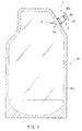
- FIGS. 1, 2A to 2C show a first embodiment of the invention.
- a closure 1 is designed to be attached to, for example, a refill container 50 sold separately from a main container, which contains food or detergent.
- the container 50 is formed by adhering, by fusion, a plurality of relatively cheap soft synthetic resin sheets 50a.
- the hatched portion is the area of adhesion by fusion.
- the closure 1 comprises a main body section (spout section) 2 in which a communication hole section 2a for passing the contents therethrough is formed and a cylindrical closure main body 20 which is connected to the spout section 2 with a thin-thickness section 20a interposed therebetween.
- the closure main body 20 has a sealing wall 20b for preventing leakage of the contents.
- These sections are made of a synthetic resin such as polypropylene, polyethylene, etc. such that they are formed integral with each other as one body.
- the spout section 2 is adhered, by fusion, to an appropriate portion of the synthetic resin sheets 50a of the container 50 during the fusion process in which the sheets 50a are adhered to each other.
- a to-be-fused section 3 of a shape which enables easy adhesion of the closure to the synthetic resin sheets of the container and has, for example, a substantially elliptical or circular section forms an intermediate portion of the spout section 2.
- the spout section 2 has circular cross section, the portion of the spout section 2 through which the contents passes can be formed in various shapes such as an elliptical one, a rectangular one, etc.
- the closure main body 20 is coupled, as one body, with the spout section 2 via the thin-thickness section 20a.
- the thin-thickness section 20a is used to keep the container in a contents-sealed state, and ripped to take the contents out of the container. To this end, it is desirable to set the thickness of the thin-thickness section 20a at about 0.1 mm - 0.5 mm.
- a pinch section 25 is provided at the end of the closure main body 20 opposed to the thin-thickness section.
- the pinch section 25 is formed so that the thin-thickness section 20a can be easily ripped with the pinch section 25 pinched by fingers, thereby easily separating the closure main body 20 from the spout section 2.
- the pinch section 25 is ring-shaped and surrounds the closure main body 20 above it, so that it can be easily pinched.
- the ring-shaped pinch section 25 and the closure main body 20 are coupled with each other by means of coupling sections 25a, 25a and 25b which are provided at regular circumferential intervals.
- the coupling sections 25a have a narrow width so that they can be easily cut, while the coupling section 25b has a wide width so that it cannot be cut.
- the coupling sections 25a are cut out, and the ripping operation is performed using the fingers, with the pinch section 25 pinched by the fingers.
- a sealing projection (flange) 20c which can tightly contact the inner periphery of the spout section 2 where the closure main body is fitted in the spout section 2, is provided on the outer periphery of the closure main body 20.
- the structure shown in FIG. 2B has a single projection 20c, more reliable sealing is achieved if a plurality of projections are provided axially, as in another embodiment which will be described later.
- the sealing wall 20b is formed on the top-side of the closure main body 20, it may be formed on the lower-end side of the closure main body 20 lower than the thin-thickness section 20a. That is, no limitation is given to the position of the sealing wall.
- FIGS. 3A - 3E show a second embodiment of the invention.
- a closure main body 30 is formed of a cylindrical member which has a thin-thickness section 30a coupled with the inner periphery of the spout section 2 as in the first embodiment, and also has a sealing wall 30b on the main-body side.
- the sealing wall 30b is located lower than the thin-thickness section 30a (within the main body).
- two sealing projections are formed at two axial portions of the outer peripheral surface of the closure main body 30 such that they are in tight contact with the inner peripheral surface of the spout section 2.
- a pinch section 35 to be used to separate the closure main body 30 from the spout section 2 is coupled, via a coupling section 35a, to a brim section 30e provided at the upper end of the closure main body 30.
- the pinch section 35 is shaped like a substantially triangular ring.
- the periphery of the closure main body 30 is partially cut out over predetermined ranges in a direction perpendicular to the direction of communication (the resultant cutouts are indicated by reference numeral 36), and the pinch-side of the closure main body and the thin-thickness side thereof are coupled by means of coupling sections 36a and 36b which are located circumferentially opposite to each other.
- the formation of the cutouts and the coupling sections provide the following advantage:
- the closure main body and the spout section are coupled to each other by the thin-thickness section through 360 DEG, as described above. Accordingly, to start ripping, it is necessary to apply a force through 360°, which means that a relatively large pinching force is needed.
- This embodiment is constructed such that the pinching force is concentrically applied to a certain portion of the closure main body to enable the ripping operation with a small amount of force.
- the coupling section 36b located below the coupling section 35a which couples the pinch section 35 to the closure main body 30 is made to a width narrower than the coupling section 36a opposed to the coupling section 36b. This being so, the coupling section 36b can be easily cut.
- the pinch section 35 is pinched and raised.
- the raising force is exerted on the coupling section 35a, thereby cutting the coupling section 36b located below the coupling section 35a.
- the raising force is concentrated on the coupling section 36a and also on a point P of the thin-thickness section 30a located below the coupling section 36a.
- the thin-thickness section 30a starts to be ripped from the point P, thereby ripping the overall thin-thickness section.
- ripping or separation can be performed easily.
- the thus-separated closure main body 30 is again dropped into the spout section 2, thereby re-sealing the container using the sealing wall 30b and the projections 30c and 30d. Even if the projection 30d is not formed in this embodiment, the re-sealing state can be realized.
- FIGS. 4A - 4E show a third embodiment of the invention.
- this embodiment there are provided two circumferentially symmetrical cutouts 46, and two coupling sections 46a and 46b of the same width, which width prevents them from being cut.
- the force to open the closure is concentrated on the coupling section 46b and hence on a point P of the thin-thickness section 30a located below the coupling section 46b, thereby ripping the thin-thickness section 30a from the point P.
- the closure main body 30 can be easily separated along the entire thin-thickness section 30a.
- the closure main body 30 is prevented from becoming hinged even after the separation, which means that the shape of the closure main body can be kept unchanged when re-sealing the container, and hence the container can be sealed in a reliable manner.
- the shapes, positions or number of coupling sections provided by forming cutouts can be modified depending upon the manner of use.
- the projection 30d may not be formed as in the second embodiment.
- the closure to be attached to the container has a one-piece structure in which the spout section and the closure main body are connected to each other at the thin-thickness section. Accordingly, a closure of a simple structure can be made at a low cost. Moreover, since the closure is constructed such that the closure main body is fitted in the spout section to thereby re-seal the container, leakage or dripping of liquid can be effectively prevented when performing the re-sealing operation.
- FIG. 5 - FIG. 7E show a fourth embodiment of the invention. As is shown in FIG. 5, a closure 1 is attached to a container 50 as in the first embodiment.
- a closure main body 60 has a pinch section 65 at an end opposite to a thin-thickness section 60a thereof.
- the pinch section 65 is to be pinched by the fingers to thereby rip the closure main body 60 at the thin-thickness section 60a and separate it from the spout section 2.
- the pinch section 65 is shaped like a tongue which projects in one direction above the closure main body 60 to facilitate its handling.
- the direction of projection of the pinch section (tongue section) 65 is set parallel to a rib provided between coupling sections, which will be described later.
- the closure main body 60 After being ripped from the spout section 2 at the thin-thickness section 60a as a result of pinching the pinch section 65, the closure main body 60 is fitted in the spout section 2, which enables re-sealing of the container.
- a sealing wall 60b is formed below the thin-thickness section 60a, and sealing projections (flanges) 60c and 60d, which can tightly contact the inner periphery of the spout section 2 where the closure main body is fitted in the spout section, are provided on the outer periphery of the closure main body 60 with a predetermined axial space interposed therebetween.
- the periphery of the closure main body 60 is partially cut out between the projections 60c and 60d over predetermined ranges in a direction perpendicular to the direction of communication, thereby forming cutouts 66.
- the cutouts 66 circumferentially extend through substantially 180 and are opposed to each other, with the result that the pinch section side of the closure main body and the thin-thickness section thereof are coupled by means of two diametrically opposed coupling sections 66a and 66b of the same width.
- the closure main body 60 and the spout section 2 are coupled to each other by the thin-thickness section 60a through 360°, as described above. Accordingly, to start ripping, it is necessary to apply a force through 360°, which means that a relatively large pinching force is needed.
- This embodiment is constructed such that the pinching force is concentrically applied to a certain portion of the closure main body to enable the ripping operation with a small amount of force.
- the force occurring during ripping is concentrated on the coupling sections 66a and 66b, and in particular, the tensile force of the ripping operation is concentrated on the coupling section 66b.
- the force is concentrically exerted on the point P of the thin-thickness section 60a located below the coupling section 66b, which enables extremely easy ripping of the thin-thickness section 60a from the point P.
- the positions of the coupling sections and the structure of the pinch section 65 should be determined to enable most efficient concentration of force.
- the pinch section 65 is shaped like a tongue which projects in one direction above the closure main body 60 as shown in FIG. 7A
- the user will grasp an end (an adjusting section 5) of the spout section 2 with one hand, and pinch the pinch section 65 with the fingers of the other hand, thereby pulling the pinch section 65 in a direction indicated by the arrows.
- it is efficient to form the cutouts 66 such that the coupling sections 66a and 66b are arranged in the pulling direction (i.e. the projecting direction of the pinch section 65).
- a rib is provided on the inner peripheral surface of the closure main body 60 so that the force which can be exerted in any direction depending upon the ripping operation will be efficiently concentrated, and also so that neither the closure main body 60 will be deformed nor the generated force will be dispersed when the ripping operation is performed.
- the rib should be extended between the coupling sections 66a and 66b as indicated by reference numeral 70 in FIG. 7C.
- the rib 70 enables efficient transmission of force during ripping, and hence the closure main body 60 can be easily ripped by a relatively weak force.
- the rib 70 enables concentration of the force on the coupling sections 66a and 66b.
- the rib 70 can also reinforce the closure main body 60, and therefore the closure main body can be prevented from being deformed during ripping. As a result, the closure main body can be more easily and reliably separated from the spout section.
- FIGS. 8 - 9E show a fifth embodiment of the invention.
- a pinch section incorporated in the closure main body 60 consists of two tongue sections 75, 75 which diametrically project from the outer periphery of the closure main body 60.
- the same rib 70 as in the fourth embodiment is provided on the inner surface of the cylindrical closure main body 60 such that it is parallel to the projecting direction of the tongue sections 75.
- Another rib 80 is provided on the inner surface of the closure main body 60 perpendicular to the rib 70.
- the pinch sections (tongue sections) 75 are shaped as shown in those figures, it is possible that the user will twist the tongue sections 75. Even when the tongue sections are twisted, breakage of the coupling sections 66a and 66b due to deformation of the closure will not occur since the entire closure main body 60 is effectively reinforced by the ribs 70 and 80.
- the rib structure (the shape, thickness or position of each rib, the number of ribs, etc.) employed in the closure main body 60 can be modified in various manners, depending upon the shape of the pinch section and how the force is exerted thereon. Also, the ribs may be formed at different levels, depending upon their arrangement direction. In the FIG. 9B case, for example, the rib 80 is at a level lower than the rib 70. However, to obtain a sufficient reinforcing effect, it is preferable that the upper end of each rib should be at a level higher than the cutouts 66.
- the projection of the spout section 2 within the container should be set short (specifically, as short as permits pinching of it), so that the contents can easily flow therethrough when the container 50 is inclined. It is also preferable that an adjusting section 5 for adjusting the flow of the contents is provided at the projection end of the spout section. Specifically, as shown in FIG. 10A, the projection end of the spout section 2 has two inclined portions 5a which are gradually separated from inner surface of the sheet member of the container from near the fused portion to the tip of the section 2 within the container.
- the shape of the projection end of the spout section 2 is not limited to the inclined one, but may be modified in various manners. It suffices if the projection end can control the flow rate. For example, the projection end may have a single inclined portion 5c as shown in FIG. 10B. Moreover, any structure other than that which includes an inclined portion may be employed. It suffices if the opening of the spout section 2 can be sealed.
- a closure 90 to be attached to the container 50 includes a spout section 92 which projects within the container for passing the contents therethrough, and a to-be-fused section 93 of a substantially elliptic or circular section as shown in FIG. 11B or 11C.
- An adjusting section 5 for adjusting the flow of the contents as described above is formed at the projection end of the spout section 92.
- the other end of the spout section 92 is constructed to be covered with a cap 95.
- the adjusting section 5 is applicable to various types of closures.
- the invention is not limited to the above-described embodiments, but may be modified in various manners.
- the closure of the invention can be attached to a plastic bottle, as well as containers made of synthetic resin sheets shown in FIGS. 1 and 5.
- the section or length of each of the spout section and the closure main body, the tip configuration of the spout section, the structure of the pinch section, etc. can be modified in various manners.
Description
- This invention relates to a closure to be attached to a container for containing a fluid such as a liquid food, seasoning, detergent, etc. (hereinafter referred to as "contents").
- A conventional container for containing contents as above is provided in the form of, for example, a plastic bottle or by, for example, fusion of soft synthetic resin sheets, and has a closure of a synthetic resin through which the contents come out. This closure has a function of sealing the contents in the container when they are being sold, and re-sealing the container after it is once opened.
- The re-sealing function of the conventional closure is realized by a structure which consists of a plurality of closure members (a so-called two-piece structure is well known). In a case where such a two-piece closure is attached to a plastic bottle, it comprises a main body to be attached to the opening of the bottle, and a cap which can be attached to and detached from the main body. The main body has a closing section of a thin thickness provided with a score line and disposed to close the opening of the bottle. The closing section is provided with a pinch section which facilitates ripping of the closing section along the score line. The bottle opening is opened along the score line by pinching the pinch section and ripping the closing section along the line. After the contents are taken out of it, the bottle is again sealed by attaching the cap to the main body of the closure.
- The conventional closure with the re-sealing function has the aforementioned two-piece structure and is therefore inevitably expensive. Moreover, since the opening is formed by ripping the closing section of the main body along the score line provided therein, there exists a space between the opening and the cap, into which the liquid may easily leak or drip. This is inconvenient during use.
- To avoid it, it is considered to impart to the closure a one-piece structure in which those structural members are formal integral which each other as one body. However, it is difficult to construct the closure such that the main body and the cap can be easily and reliably separated from each other during use, and be reliably coupled to each other in a liquid-tight manner. In other words, if both the main body and the cap cannot be separated unless a strong force is applied thereto, or if they are separated at inappropriate portions thereof when the user has handled the closure in an optimal manner, the closure will be hard for the user handle.
- US-A-5 636 771 describes a frangible pour spout construction comprising a pull ring held down to a latched position by a pair of hooks.
- It is the object of the invention to provide a closure which is to be attached to the plastic bottle or a container formed of, for example, soft synthetic resin sheets, has a function for reliably re-sealing the bottle or container in a simple manner at low cost, and can be easily handled.
- This summary of the invention does not necessarily describe all necessary features so that the invention may also be a sub-combination of these described features.
- The invention can be more fully under stood from the following detailed description when taken in conjunction with the accompanying drawings, in which:
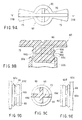
- FIG. 1 is a view of a closure according to a first embodiment of the invention, showing a state in which the closure is attached to a container formed of synthetic resin sheets;
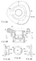
- FIGS. 2A - 2C show the closure of FIG. 1, FIG. 2A being a plan view, FIG. 2B a partial sectional view when viewed laterally, and FIG. 2C a partial sectional view taken along lines IIC - IIC of FIG. 2B;
- FIGS. 3A - 3E show a second embodiment of the invention, FIG. 3A being a plan view, FIG. 3B a sectional view showing a closure main body, FIG. 3C a sectional view taken along lines IIIC - IIIC of FIG. 3B, FIG. 3D a view showing a cutout portion, which appears in FIG. 3C, when viewed from the left side, and FIG. 3E a view showing a cutout portion, which appears in FIG. 3C, when viewed from the right side;
- FIGS. 4A - 4E show a third embodiment of the invention, FIG. 4A being a plan view, FIG. 4B a sectional view showing a closure main body, FIG. 4C a sectional view taken along lines IVC - IVC of FIG. 4B, FIG. 4D a view showing a cutout portion, which appears in FIG. 4C, when viewed from the left side, and FIG. 4E a view showing a cutout portion, which appears in FIG. 4C, when viewed from the right side;
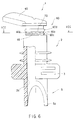
- FIG. 5 is a view of a closure according to a fourth embodiment of the invention, showing a state in which the closure is attached to a container formed of synthetic resin sheets;
- FIG. 6 is an enlarged partially broken view showing the closure of FIG. 5;
- FIGS. 7A - 7E show the closure of FIG. 5, FIG. 7A being a plan view, FIG. 7B a sectional view taken along lines VIIB - VIIB of FIG. 7A, FIG. 7C a sectional view taken along lines VIIC - VIIC of FIG. 6, FIG. 7D a view showing a cutout portion, which appears in FIG. 7C, when viewed from the left side, and FIG. 7E a view showing a cutout portion, which appears in FIG. 7C, when viewed from the right side;
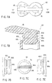
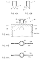
- FIG. 8 is an enlarged partially broken view showing a closure according to a fifth embodiment of the invention;
- FIGS. 9A - 9E show the closure of FIG. 8, FIG. 9A being a plan view, FIG. 9B a sectional view taken along lines IXB - IXB of FIG. 9A, FIG. 9C a sectional view taken along lines IXC - IXC of FIG. 8, FIG. 9D a view showing a cutout portion, which appears in FIG. 9C, when viewed from the left side, and FIG. 9E a view showing a cutout portion, which appears in FIG. 9C, when viewed from the right side;
- FIG. 10A is a view showing a flow adjusting mechanism formed at a spout section projecting into a container, and FIG. 10B a view showing a modification of the flow adjusting mechanism; and
- FIG. 11A shows another example of the container with the flow adjusting mechanism, FIG. 11B being a sectional view taken along lines XIB - XIB of FIG. 11A, FIG. 11C a sectional view showing another example of the spout section.
-
- FIGS. 1, 2A to 2C show a first embodiment of the invention. As is shown in FIG. 1, a
closure 1 is designed to be attached to, for example, arefill container 50 sold separately from a main container, which contains food or detergent. Thecontainer 50 is formed by adhering, by fusion, a plurality of relatively cheap softsynthetic resin sheets 50a. In FIG. 1, the hatched portion is the area of adhesion by fusion. - The
closure 1 comprises a main body section (spout section) 2 in which a communication hole section 2a for passing the contents therethrough is formed and a cylindrical closuremain body 20 which is connected to thespout section 2 with a thin-thickness section 20a interposed therebetween. The closuremain body 20 has a sealingwall 20b for preventing leakage of the contents. These sections are made of a synthetic resin such as polypropylene, polyethylene, etc. such that they are formed integral with each other as one body. Thespout section 2 is adhered, by fusion, to an appropriate portion of thesynthetic resin sheets 50a of thecontainer 50 during the fusion process in which thesheets 50a are adhered to each other. A to-be-fused section 3 of a shape which enables easy adhesion of the closure to the synthetic resin sheets of the container and has, for example, a substantially elliptical or circular section forms an intermediate portion of thespout section 2. Although thespout section 2 has circular cross section, the portion of thespout section 2 through which the contents passes can be formed in various shapes such as an elliptical one, a rectangular one, etc. - The closure
main body 20 is coupled, as one body, with thespout section 2 via the thin-thickness section 20a. The thin-thickness section 20a is used to keep the container in a contents-sealed state, and ripped to take the contents out of the container. To this end, it is desirable to set the thickness of the thin-thickness section 20a at about 0.1 mm - 0.5 mm. - A
pinch section 25 is provided at the end of the closuremain body 20 opposed to the thin-thickness section. Thepinch section 25 is formed so that the thin-thickness section 20a can be easily ripped with thepinch section 25 pinched by fingers, thereby easily separating the closuremain body 20 from thespout section 2. In the example of FIGS. 2A - 2C, thepinch section 25 is ring-shaped and surrounds the closuremain body 20 above it, so that it can be easily pinched. The ring-shapedpinch section 25 and the closuremain body 20 are coupled with each other by means ofcoupling sections 25a, 25a and 25b which are provided at regular circumferential intervals. To facilitate the actual ripping operation, the coupling sections 25a have a narrow width so that they can be easily cut, while thecoupling section 25b has a wide width so that it cannot be cut. By virtue of this structure, during the actual use, the coupling sections 25a are cut out, and the ripping operation is performed using the fingers, with thepinch section 25 pinched by the fingers. - After being ripped from the
spout section 2 at the thin-thickness section 20a as a result of pinching thepinch section 25, the closuremain body 20 is fitted into thespout section 2, which enables re-sealing of the container. A sealing projection (flange) 20c, which can tightly contact the inner periphery of thespout section 2 where the closure main body is fitted in thespout section 2, is provided on the outer periphery of the closuremain body 20. In other words, when the closuremain body 20 has been dropped into thespout section 2, theprojection 20c is brought into tight contact with the inner periphery of thespout section 2, thereby preventing leakage of the contents together with the sealingwall 20b of the closuremain body 20. - Although the structure shown in FIG. 2B has a
single projection 20c, more reliable sealing is achieved if a plurality of projections are provided axially, as in another embodiment which will be described later. Further, although in the structure, the sealingwall 20b is formed on the top-side of the closuremain body 20, it may be formed on the lower-end side of the closuremain body 20 lower than the thin-thickness section 20a. That is, no limitation is given to the position of the sealing wall. - Other embodiments of the invention will be described. In the embodiments described below, only sections different from those of the first embodiment will be described.
- FIGS. 3A - 3E show a second embodiment of the invention.
- A closure
main body 30 according to this embodiment is formed of a cylindrical member which has a thin-thickness section 30a coupled with the inner periphery of thespout section 2 as in the first embodiment, and also has a sealingwall 30b on the main-body side. The sealingwall 30b is located lower than the thin-thickness section 30a (within the main body). As is indicated byreference numerals main body 30 such that they are in tight contact with the inner peripheral surface of thespout section 2. - A
pinch section 35 to be used to separate the closuremain body 30 from thespout section 2 is coupled, via acoupling section 35a, to abrim section 30e provided at the upper end of the closuremain body 30. Thepinch section 35 is shaped like a substantially triangular ring. Thus coupling thepinch section 35 to the closuremain body 30 by thesingle coupling section 35a of a wide width enables easy pinching of the pinch section when ripping. - Also in this embodiment, the periphery of the closure
main body 30 is partially cut out over predetermined ranges in a direction perpendicular to the direction of communication (the resultant cutouts are indicated by reference numeral 36), and the pinch-side of the closure main body and the thin-thickness side thereof are coupled by means ofcoupling sections 36a and 36b which are located circumferentially opposite to each other. The formation of the cutouts and the coupling sections provide the following advantage: - When pinching the
pinch section 35 to rip the closure main body, the closure main body and the spout section are coupled to each other by the thin-thickness section through 360 DEG, as described above. Accordingly, to start ripping, it is necessary to apply a force through 360°, which means that a relatively large pinching force is needed. This embodiment is constructed such that the pinching force is concentrically applied to a certain portion of the closure main body to enable the ripping operation with a small amount of force. Specifically, thecoupling section 36b located below thecoupling section 35a which couples thepinch section 35 to the closuremain body 30 is made to a width narrower than the coupling section 36a opposed to thecoupling section 36b. This being so, thecoupling section 36b can be easily cut. - The operation performed in the above-described structure to open the closure main body will now be described. First, the
pinch section 35 is pinched and raised. The raising force is exerted on thecoupling section 35a, thereby cutting thecoupling section 36b located below thecoupling section 35a. Then, the raising force is concentrated on the coupling section 36a and also on a point P of the thin-thickness section 30a located below the coupling section 36a. As a result, the thin-thickness section 30a starts to be ripped from the point P, thereby ripping the overall thin-thickness section. Thus, ripping or separation can be performed easily. - The thus-separated closure
main body 30 is again dropped into thespout section 2, thereby re-sealing the container using the sealingwall 30b and theprojections projection 30d is not formed in this embodiment, the re-sealing state can be realized. - FIGS. 4A - 4E show a third embodiment of the invention. In this embodiment, there are provided two circumferentially
symmetrical cutouts 46, and twocoupling sections 46a and 46b of the same width, which width prevents them from being cut. In this structure, the force to open the closure is concentrated on thecoupling section 46b and hence on a point P of the thin-thickness section 30a located below thecoupling section 46b, thereby ripping the thin-thickness section 30a from the point P. As a result, the closuremain body 30 can be easily separated along the entire thin-thickness section 30a. - Moreover, since the
coupling section 46b is not cut, the closuremain body 30 is prevented from becoming hinged even after the separation, which means that the shape of the closure main body can be kept unchanged when re-sealing the container, and hence the container can be sealed in a reliable manner. - As described above, the shapes, positions or number of coupling sections provided by forming cutouts can be modified depending upon the manner of use. Naturally, the
projection 30d may not be formed as in the second embodiment. - Further, as described above, the closure to be attached to the container has a one-piece structure in which the spout section and the closure main body are connected to each other at the thin-thickness section. Accordingly, a closure of a simple structure can be made at a low cost. Moreover, since the closure is constructed such that the closure main body is fitted in the spout section to thereby re-seal the container, leakage or dripping of liquid can be effectively prevented when performing the re-sealing operation.
- FIG. 5 - FIG. 7E show a fourth embodiment of the invention. As is shown in FIG. 5, a
closure 1 is attached to acontainer 50 as in the first embodiment. - A closure
main body 60 has apinch section 65 at an end opposite to a thin-thickness section 60a thereof. Thepinch section 65 is to be pinched by the fingers to thereby rip the closuremain body 60 at the thin-thickness section 60a and separate it from thespout section 2. As is shown in FIG. 6, thepinch section 65 is shaped like a tongue which projects in one direction above the closuremain body 60 to facilitate its handling. The direction of projection of the pinch section (tongue section) 65 is set parallel to a rib provided between coupling sections, which will be described later. - After being ripped from the
spout section 2 at the thin-thickness section 60a as a result of pinching thepinch section 65, the closuremain body 60 is fitted in thespout section 2, which enables re-sealing of the container. A sealingwall 60b is formed below the thin-thickness section 60a, and sealing projections (flanges) 60c and 60d, which can tightly contact the inner periphery of thespout section 2 where the closure main body is fitted in the spout section, are provided on the outer periphery of the closuremain body 60 with a predetermined axial space interposed therebetween. In other words, when the closuremain body 60 has been dropped into thespout section 2, theprojections spout section 2, thereby preventing leakage of the contents, together with the sealingwall 60b of the closuremain body 60. - The periphery of the closure
main body 60 is partially cut out between theprojections cutouts 66. In this embodiment, thecutouts 66 circumferentially extend through substantially 180 and are opposed to each other, with the result that the pinch section side of the closure main body and the thin-thickness section thereof are coupled by means of two diametricallyopposed coupling sections cutouts 66 as above provides the following advantage: - When pinching the
pinch section 65 to rip the closure main body, the closuremain body 60 and thespout section 2 are coupled to each other by the thin-thickness section 60a through 360°, as described above. Accordingly, to start ripping, it is necessary to apply a force through 360°, which means that a relatively large pinching force is needed. This embodiment is constructed such that the pinching force is concentrically applied to a certain portion of the closure main body to enable the ripping operation with a small amount of force. - As described above, where the
cutouts 66 are formed in the closuremain body 66, the force occurring during ripping is concentrated on thecoupling sections coupling section 66b. As a result, the force is concentrically exerted on the point P of the thin-thickness section 60a located below thecoupling section 66b, which enables extremely easy ripping of the thin-thickness section 60a from the point P. - It is preferable that the positions of the coupling sections and the structure of the
pinch section 65 should be determined to enable most efficient concentration of force. Specifically, where thepinch section 65 is shaped like a tongue which projects in one direction above the closuremain body 60 as shown in FIG. 7A, to rip the closure main body, the user will grasp an end (an adjusting section 5) of thespout section 2 with one hand, and pinch thepinch section 65 with the fingers of the other hand, thereby pulling thepinch section 65 in a direction indicated by the arrows. In light of this, it is efficient to form thecutouts 66 such that thecoupling sections - Moreover, a rib is provided on the inner peripheral surface of the closure
main body 60 so that the force which can be exerted in any direction depending upon the ripping operation will be efficiently concentrated, and also so that neither the closuremain body 60 will be deformed nor the generated force will be dispersed when the ripping operation is performed. To this end, it is preferable in the above structure that the rib should be extended between thecoupling sections reference numeral 70 in FIG. 7C. Therib 70 enables efficient transmission of force during ripping, and hence the closuremain body 60 can be easily ripped by a relatively weak force. Further, even when the force from thepinch section 65 does not act in the direction indicated by the arrows, therib 70 enables concentration of the force on thecoupling sections rib 70 can also reinforce the closuremain body 60, and therefore the closure main body can be prevented from being deformed during ripping. As a result, the closure main body can be more easily and reliably separated from the spout section. - FIGS. 8 - 9E show a fifth embodiment of the invention. In this embodiment, a pinch section incorporated in the closure
main body 60 consists of twotongue sections main body 60. Thesame rib 70 as in the fourth embodiment is provided on the inner surface of the cylindrical closuremain body 60 such that it is parallel to the projecting direction of thetongue sections 75. Anotherrib 80 is provided on the inner surface of the closuremain body 60 perpendicular to therib 70. - The structure in which the
rib 80 is provided perpendicularly in addition to therib 70 efficiently reinforces the closuremain body 60, thereby preventing deformation of the closuremain body 60 when opening the closure. Where in particular, the pinch sections (tongue sections) 75 are shaped as shown in those figures, it is possible that the user will twist thetongue sections 75. Even when the tongue sections are twisted, breakage of thecoupling sections main body 60 is effectively reinforced by theribs main body 60 can be modified in various manners, depending upon the shape of the pinch section and how the force is exerted thereon. Also, the ribs may be formed at different levels, depending upon their arrangement direction. In the FIG. 9B case, for example, therib 80 is at a level lower than therib 70. However, to obtain a sufficient reinforcing effect, it is preferable that the upper end of each rib should be at a level higher than thecutouts 66. - Further, concerning the
spout section 2 of theclosure 1 constructed as above, it is preferable that the projection of thespout section 2 within the container should be set short (specifically, as short as permits pinching of it), so that the contents can easily flow therethrough when thecontainer 50 is inclined. It is also preferable that anadjusting section 5 for adjusting the flow of the contents is provided at the projection end of the spout section. Specifically, as shown in FIG. 10A, the projection end of thespout section 2 has twoinclined portions 5a which are gradually separated from inner surface of the sheet member of the container from near the fused portion to the tip of thesection 2 within the container. When the portion of the sheet member which is close to the projection of thespout section 2 has been pinched from outside, inner surface portions of the sheet member are brought into contact with theinclined sides 5a to thereby seal the opening of thespout section 2. This being so, the flow of the contents can be controlled by pinching the projection of thespout section 2 while inclining thecontainer 50, and adjusting the pinching force. Accordingly, dripping of the contents due to overflowing can be avoided when, for example, the contents of the container are shifted into another container. The shape of the projection end of thespout section 2 is not limited to the inclined one, but may be modified in various manners. It suffices if the projection end can control the flow rate. For example, the projection end may have a single inclined portion 5c as shown in FIG. 10B. Moreover, any structure other than that which includes an inclined portion may be employed. It suffices if the opening of thespout section 2 can be sealed. - Application of the aforementioned flow adjusting mechanism is not limited to the above-described closure, but also to a closure as shown in FIGS. 11A - 11C. In this case, a
closure 90 to be attached to thecontainer 50 includes aspout section 92 which projects within the container for passing the contents therethrough, and a to-be-fused section 93 of a substantially elliptic or circular section as shown in FIG. 11B or 11C. Anadjusting section 5 for adjusting the flow of the contents as described above is formed at the projection end of thespout section 92. The other end of thespout section 92 is constructed to be covered with acap 95. Thus, the adjustingsection 5 is applicable to various types of closures. - The invention is not limited to the above-described embodiments, but may be modified in various manners. For example, the closure of the invention can be attached to a plastic bottle, as well as containers made of synthetic resin sheets shown in FIGS. 1 and 5. In addition, the section or length of each of the spout section and the closure main body, the tip configuration of the spout section, the structure of the pinch section, etc. can be modified in various manners.
Claims (12)
- A closure (1) to be attached to a container (50) comprising:characterized in that at least one cutout (36, 46, 66) is formed in the closure main body above the thin-thickness connecting section so as to provide at least one coupling section (25a, 25b, (36a, 36b, 46a, 46b, 66a, 66b) which couple a pinch section side to a thin-thickness connecting section side.a spout section (2) through which contents of the container pass;a closure main body (20, 30, 60) connected to the spout section (2) with a thin-thickness connecting section (20a, 30a, 60a) interposed therebetween, the closure main body (20, 30, 60) having a projection (20c, 30c, 30d, 60c, 60d) to be fitted into the spout section such that it tightly contacts an inner peripheral surface portion of the spout section (2), and a sealing wall (20b, 30b, 60b) for preventing leakage of the contents; anda pinch section (25, 35, 65, 75) formed as a part of the closure main body,
- A closure according to claim 1, characterized in that the coupling sections (36a, 36b) are opposed to each other, and have different widths.
- A closure according to claim 2, characterized in that a coupling section (35a) of the pinch section and the closure main body is located above that one of the coupling sections which has a narrower width.
- A closure according to claim 1, characterized in that the coupling sections (46a, 46b, 66a, 66b) are opposed to each other, and have the same width.
- A closure according to claim 4, characterized in that a coupling section (35a) of the pinch section and the closure main body is located above at least one of the coupling sections.
- A closure according to claim 1, characterized that the pinch section (25, 35, 65, 75) is ring-shaped.
- A closure according to claim 1, characterized by further comprising a rib (70) extending between inner surface portions of the closure main body.
- A closure according to claim 7, characterized in that the rib (70, 80) extends between the coupling sections (36a, 36b, 46a, 46b, 66a, 66b).
- A closure according to claim 1, characterized by further comprising a first rib (70) extending between the coupling sections, and a second rib (80) perpendicular to the first rib.
- A closure according to claim 8, characterized in that the pinch section (65, 75) formed as the part of the closure main body extends parallel to the rib (70) which extends between the coupling sections.
- A closure according to claim 10, characterized in that the pinch section non-symmetrically projects from the closure main body.
- A closure according to claim 1, characterized in that:a plurality of cutouts (36, 46, 66) are formed in the closure main body and each of said plurality of cutouts is defined by two coupling sections (25a, 25b, 36a, 36b, 46a, 46b, 66a, 66b).
Applications Claiming Priority (4)
| Application Number | Priority Date | Filing Date | Title |
|---|---|---|---|
| JP10029637A JP2920136B1 (en) | 1998-02-12 | 1998-02-12 | Opening cap |
| JP2963798 | 1998-02-12 | ||
| JP12080698 | 1998-04-30 | ||
| JP10120806A JP2930581B1 (en) | 1998-04-30 | 1998-04-30 | Opening cap |
Publications (3)
| Publication Number | Publication Date |
|---|---|
| EP0936156A2 EP0936156A2 (en) | 1999-08-18 |
| EP0936156A3 EP0936156A3 (en) | 1999-12-15 |
| EP0936156B1 true EP0936156B1 (en) | 2003-05-28 |
Family
ID=26367858
Family Applications (1)
| Application Number | Title | Priority Date | Filing Date |
|---|---|---|---|
| EP99102481A Expired - Lifetime EP0936156B1 (en) | 1998-02-12 | 1999-02-10 | Container closure |
Country Status (3)
| Country | Link |
|---|---|
| US (1) | US6158622A (en) |
| EP (1) | EP0936156B1 (en) |
| DE (1) | DE69908197T2 (en) |
Families Citing this family (13)
| Publication number | Priority date | Publication date | Assignee | Title |
|---|---|---|---|---|
| DE10021541C2 (en) * | 2000-05-03 | 2002-10-17 | Guenter Grittmann | Retractable tap with original fuse for liquid containers |
| EP1337439B1 (en) * | 2000-11-01 | 2007-03-28 | Jung-Min Lee | Liquid container |
| US6439429B1 (en) | 2001-07-05 | 2002-08-27 | Seaquist Closures Foreign, Inc. | Tamper-evident closure and spout fitment for a pouch |
| EP1980498A1 (en) * | 2007-04-12 | 2008-10-15 | Rexam Home and Personal Care | One-piece dispensing spout with a cap attached to a tube with a breakable web of material |
| DE102009026264A1 (en) * | 2009-07-28 | 2011-02-03 | Hans-Jürgen Hopf | filler pipe |
| US20110132941A1 (en) * | 2009-12-08 | 2011-06-09 | Kim Sang Soon | Spout for a pouch |
| SE535280C2 (en) * | 2010-09-07 | 2012-06-12 | Petro Pack Ab | Method of making packaging closure |
| JP5656259B2 (en) * | 2011-03-22 | 2015-01-21 | 日本クロージャー株式会社 | Folding spout |
| US11206838B2 (en) | 2013-04-11 | 2021-12-28 | General Mills, Inc. | Batter compositions, packaged batter products, and related methods |
| NL2010938C2 (en) * | 2013-06-07 | 2014-12-09 | Ipn Ip Bv | A collapsible pouch provided with a closure assembly. |
| US10005602B2 (en) | 2013-06-07 | 2018-06-26 | Scholle Ipn Ip Bv | Collapsible pouch provided with a closure assembly |
| US10093105B2 (en) | 2016-04-22 | 2018-10-09 | Canon Kabushiki Kaisha | Liquid storage container and liquid ejection apparatus |
| EP3728065B1 (en) * | 2017-12-18 | 2022-03-23 | Guala Pack S.p.A. | Spout and cap-spout assembly |
Family Cites Families (12)
| Publication number | Priority date | Publication date | Assignee | Title |
|---|---|---|---|---|
| US2750068A (en) * | 1955-03-29 | 1956-06-12 | Sheffield Tube Corp | Container closure |
| AT347325B (en) * | 1973-07-12 | 1978-12-27 | Patentkommerz Ag | PLASTIC CLOSURE FOR SHEET METAL BALLS |
| JPS50136618A (en) * | 1974-04-19 | 1975-10-30 | ||
| JPS61117121A (en) * | 1984-11-14 | 1986-06-04 | Agency Of Ind Science & Technol | Alpha-fe2o3 powder having ferromagnetism |
| JPH0727599B2 (en) * | 1988-07-11 | 1995-03-29 | 富士電機株式会社 | Synchronous method of measurement information at different points |
| JPH0326751A (en) * | 1989-06-22 | 1991-02-05 | Toyobo Co Ltd | Polyester resin composition |
| JPH0432949A (en) * | 1990-05-22 | 1992-02-04 | Nec Eng Ltd | I/o port address extension system |
| JPH0456623A (en) * | 1990-06-25 | 1992-02-24 | Toyota Motor Corp | Air duct structure in cowl for car body |
| JPH0544294A (en) * | 1991-08-15 | 1993-02-23 | Naka Ind Ltd | Ceiling framework |
| US5636771A (en) * | 1995-06-06 | 1997-06-10 | International Paper Company | Frangible pour spout fitment |
| US5699936A (en) * | 1995-09-08 | 1997-12-23 | Sercomp Corporation | Liquid dispensing system |
| US5911340A (en) * | 1995-09-14 | 1999-06-15 | Dai Nippon Printing Co., Ltd. | Spout assembly, spout assembly manufacturing apparatus and package with spout assembly |
-
1999
- 1999-02-09 US US09/247,150 patent/US6158622A/en not_active Expired - Lifetime
- 1999-02-10 EP EP99102481A patent/EP0936156B1/en not_active Expired - Lifetime
- 1999-02-10 DE DE69908197T patent/DE69908197T2/en not_active Expired - Lifetime
Also Published As
| Publication number | Publication date |
|---|---|
| DE69908197D1 (en) | 2003-07-03 |
| EP0936156A2 (en) | 1999-08-18 |
| EP0936156A3 (en) | 1999-12-15 |
| DE69908197T2 (en) | 2003-12-18 |
| US6158622A (en) | 2000-12-12 |
Similar Documents
| Publication | Publication Date | Title |
|---|---|---|
| EP0936156B1 (en) | Container closure | |
| US4444340A (en) | Self-sealing dispensing valve and spout assembly | |
| KR950014818B1 (en) | Quadrangular shaped container for fluids | |
| JP4575695B2 (en) | Hinge cap without pull ring | |
| EA007291B1 (en) | Flexible liquid container | |
| CA1128014A (en) | Closure cap vent | |
| EP1980498A1 (en) | One-piece dispensing spout with a cap attached to a tube with a breakable web of material | |
| US4523689A (en) | Reusable tamper-proof container | |
| EP0187820B1 (en) | Sealed container with replaceable plug insert | |
| US5769277A (en) | Dispensing closure having a force-directing removable seal | |
| AU718270B2 (en) | Plastic stop-cock for liquid containers | |
| JP2930581B1 (en) | Opening cap | |
| US4446994A (en) | Container with flexible pouring spout and sealing closure | |
| US3924745A (en) | Package construction, particularly a package designed for a single use | |
| JP5309308B2 (en) | Pouring tool | |
| US5215220A (en) | Tamper evident closure with dispensing spout and integral opening member | |
| JP2920136B1 (en) | Opening cap | |
| JP3757631B2 (en) | Liquid packaging container | |
| JP3561307B2 (en) | Pull tab for liquid container | |
| EP1565385B1 (en) | Connecting device | |
| JP4067267B2 (en) | Outlet with stopper for bag-like container | |
| US20060266774A1 (en) | Dispensing closure | |
| JP4560320B2 (en) | Plastic cap with score for opening formation | |
| KR102313824B1 (en) | Cap for container | |
| JPH0242593Y2 (en) |
Legal Events
| Date | Code | Title | Description |
|---|---|---|---|
| PUAI | Public reference made under article 153(3) epc to a published international application that has entered the european phase |
Free format text: ORIGINAL CODE: 0009012 |
|
| 17P | Request for examination filed |
Effective date: 19990416 |
|
| AK | Designated contracting states |
Kind code of ref document: A2 Designated state(s): DE FR GB IT |
|
| AX | Request for extension of the european patent |
Free format text: AL;LT;LV;MK;RO;SI |
|
| PUAL | Search report despatched |
Free format text: ORIGINAL CODE: 0009013 |
|
| AK | Designated contracting states |
Kind code of ref document: A3 Designated state(s): AT BE CH CY DE DK ES FI FR GB GR IE IT LI LU MC NL PT SE |
|
| AX | Request for extension of the european patent |
Free format text: AL;LT;LV;MK;RO;SI |
|
| AKX | Designation fees paid |
Free format text: DE FR GB IT |
|
| 17Q | First examination report despatched |
Effective date: 20010702 |
|
| GRAG | Despatch of communication of intention to grant |
Free format text: ORIGINAL CODE: EPIDOS AGRA |
|
| GRAG | Despatch of communication of intention to grant |
Free format text: ORIGINAL CODE: EPIDOS AGRA |
|
| GRAH | Despatch of communication of intention to grant a patent |
Free format text: ORIGINAL CODE: EPIDOS IGRA |
|
| GRAH | Despatch of communication of intention to grant a patent |
Free format text: ORIGINAL CODE: EPIDOS IGRA |
|
| GRAA | (expected) grant |
Free format text: ORIGINAL CODE: 0009210 |
|
| AK | Designated contracting states |
Designated state(s): DE FR GB IT |
|
| REG | Reference to a national code |
Ref country code: GB Ref legal event code: FG4D |
|
| REF | Corresponds to: |
Ref document number: 69908197 Country of ref document: DE Date of ref document: 20030703 Kind code of ref document: P |
|
| ET | Fr: translation filed | ||
| PLBE | No opposition filed within time limit |
Free format text: ORIGINAL CODE: 0009261 |
|
| STAA | Information on the status of an ep patent application or granted ep patent |
Free format text: STATUS: NO OPPOSITION FILED WITHIN TIME LIMIT |
|
| 26N | No opposition filed |
Effective date: 20040302 |
|
| PGFP | Annual fee paid to national office [announced via postgrant information from national office to epo] |
Ref country code: IT Payment date: 20120221 Year of fee payment: 14 |
|
| PGFP | Annual fee paid to national office [announced via postgrant information from national office to epo] |
Ref country code: DE Payment date: 20121201 Year of fee payment: 15 Ref country code: FR Payment date: 20130315 Year of fee payment: 15 Ref country code: GB Payment date: 20130207 Year of fee payment: 15 |
|
| REG | Reference to a national code |
Ref country code: DE Ref legal event code: R082 Ref document number: 69908197 Country of ref document: DE Representative=s name: MAI, OPPERMANN & PARTNER I. L., DE |
|
| REG | Reference to a national code |
Ref country code: DE Ref legal event code: R119 Ref document number: 69908197 Country of ref document: DE |
|
| GBPC | Gb: european patent ceased through non-payment of renewal fee |
Effective date: 20140210 |
|
| REG | Reference to a national code |
Ref country code: FR Ref legal event code: ST Effective date: 20141031 |
|
| REG | Reference to a national code |
Ref country code: DE Ref legal event code: R119 Ref document number: 69908197 Country of ref document: DE Effective date: 20140902 |
|
| PG25 | Lapsed in a contracting state [announced via postgrant information from national office to epo] |
Ref country code: GB Free format text: LAPSE BECAUSE OF NON-PAYMENT OF DUE FEES Effective date: 20140210 Ref country code: FR Free format text: LAPSE BECAUSE OF NON-PAYMENT OF DUE FEES Effective date: 20140228 Ref country code: DE Free format text: LAPSE BECAUSE OF NON-PAYMENT OF DUE FEES Effective date: 20140902 |
|
| PG25 | Lapsed in a contracting state [announced via postgrant information from national office to epo] |
Ref country code: IT Free format text: LAPSE BECAUSE OF NON-PAYMENT OF DUE FEES Effective date: 20140210 |
|
| REG | Reference to a national code |
Ref country code: DE Ref legal event code: R082 Ref document number: 69908197 Country of ref document: DE Representative=s name: MAI, OPPERMANN & PARTNER I. L., DE |