EP0935735B1 - Monitoring distortion of a spinning mirror - Google Patents
Monitoring distortion of a spinning mirror Download PDFInfo
- Publication number
- EP0935735B1 EP0935735B1 EP97939035A EP97939035A EP0935735B1 EP 0935735 B1 EP0935735 B1 EP 0935735B1 EP 97939035 A EP97939035 A EP 97939035A EP 97939035 A EP97939035 A EP 97939035A EP 0935735 B1 EP0935735 B1 EP 0935735B1
- Authority
- EP
- European Patent Office
- Prior art keywords
- reflected beam
- radiation
- monitoring
- radiation detector
- slit
- Prior art date
- Legal status (The legal status is an assumption and is not a legal conclusion. Google has not performed a legal analysis and makes no representation as to the accuracy of the status listed.)
- Expired - Lifetime
Links
- 238000012544 monitoring process Methods 0.000 title claims description 27
- 238000009987 spinning Methods 0.000 title claims description 24
- 230000005855 radiation Effects 0.000 claims description 43
- 238000000034 method Methods 0.000 claims description 22
- 230000003287 optical effect Effects 0.000 claims description 8
- 230000001419 dependent effect Effects 0.000 claims 1
- 201000009310 astigmatism Diseases 0.000 description 19
- 238000007796 conventional method Methods 0.000 description 4
- 230000000694 effects Effects 0.000 description 3
- 238000003384 imaging method Methods 0.000 description 3
- 238000012360 testing method Methods 0.000 description 3
- 238000010586 diagram Methods 0.000 description 2
- 229910052790 beryllium Inorganic materials 0.000 description 1
- ATBAMAFKBVZNFJ-UHFFFAOYSA-N beryllium atom Chemical compound [Be] ATBAMAFKBVZNFJ-UHFFFAOYSA-N 0.000 description 1
- 238000004519 manufacturing process Methods 0.000 description 1
- 230000003068 static effect Effects 0.000 description 1
Images






Classifications
-
- G—PHYSICS
- G01—MEASURING; TESTING
- G01B—MEASURING LENGTH, THICKNESS OR SIMILAR LINEAR DIMENSIONS; MEASURING ANGLES; MEASURING AREAS; MEASURING IRREGULARITIES OF SURFACES OR CONTOURS
- G01B11/00—Measuring arrangements characterised by the use of optical techniques
- G01B11/16—Measuring arrangements characterised by the use of optical techniques for measuring the deformation in a solid, e.g. optical strain gauge
-
- G—PHYSICS
- G02—OPTICS
- G02B—OPTICAL ELEMENTS, SYSTEMS OR APPARATUS
- G02B26/00—Optical devices or arrangements for the control of light using movable or deformable optical elements
- G02B26/08—Optical devices or arrangements for the control of light using movable or deformable optical elements for controlling the direction of light
- G02B26/10—Scanning systems
-
- Y—GENERAL TAGGING OF NEW TECHNOLOGICAL DEVELOPMENTS; GENERAL TAGGING OF CROSS-SECTIONAL TECHNOLOGIES SPANNING OVER SEVERAL SECTIONS OF THE IPC; TECHNICAL SUBJECTS COVERED BY FORMER USPC CROSS-REFERENCE ART COLLECTIONS [XRACs] AND DIGESTS
- Y10—TECHNICAL SUBJECTS COVERED BY FORMER USPC
- Y10S—TECHNICAL SUBJECTS COVERED BY FORMER USPC CROSS-REFERENCE ART COLLECTIONS [XRACs] AND DIGESTS
- Y10S359/00—Optical: systems and elements
- Y10S359/90—Methods
Definitions
- the present invention relates to a method and apparatus for monitoring distortion in a reflective surface of a spinning mirror.
- FIG. 1 illustrates a conventional imagesetter.
- a drum 1 carries a film to be exposed (not shown) on its inner surface.
- a laser 2 generates a collimated laser beam 3 which is directed along the axis 4 of the drum 1.
- the laser beam 3 is reflected by a spinning mirror 6 onto the film.
- the beam 3 is focused into a spot 9 by a focusing lens 5.
- the rotating mirror 6, is typically a beryllium mirror which is mounted in a mirror mounting 7 and spun at approximately 30,000rpm by a drive 8.
- items 5-8 are driven along the axis 4 of the drum 1.
- the spot 9 follows a series of azimuthal scan lines across the film.
- the geometry of the system illustrated in Figure 1 defines an axis parallel to the axis 4 of the drum 1 and perpendicular to the scan lines, which is referred to hereinafter as the X-axis.
- the geometry of the system illustrated in Figure 1 defines an azimuthal direction, substantially parallel with the scan lines, which is referred to hereinafter as the Y-axis.
- FIG. 2 illustrates the profile of the scanning dot 9 on the interior of the drum 1 with the lens 5 at two different focal positions and when dynamic astigmatism is present.
- the X and Y axes are as previously defined.
- Contour 20 is the contour of 50% beam intensity at the interior surface of the drum with the focusing lens 5 in a first axial position f x (referred to hereinafter as the horizontal focus position).
- the contour 20 is an ellipse having a maximum dimension L x and a minimum dimension S x .
- the profile of the spot 9 at the interior surface of the drum changes to give the 50% contour indicated at 21.
- the vertical dimension (ie. in the Y direction) of the spot 9 is at a minimum.
- the contour 21 is an ellipse having a maximum dimension L y and a minimum dimension S y .
- the 50% contour will be circular with a diameter greater than S y and greater than S x .
- the focal position of the lens 5 is set in the imagesetter at this intermediate position, and ideally the diameter of the spot in this focal position is as small as possible.
- the diameter of the spot 9 with the lens in the intermediate focus position may be unacceptably large. Therefore if the dynamic astigmatism is too high the mirror should not be used. Dynamic astigmatism can vary widely between different mirrors 6.
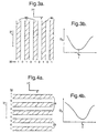
- the axial position of the focusing lens 5 is incremented between each adjacent line 30,33.
- the film is then removed, developed and inspected.
- the width of the vertical lines 30 will be at a minimum.
- a densitometer is moved across the vertical lines 30 in the X-direction, and the optical density D x output by the densitometer varies across the film as illustrated in Figure 3b, with a minimum at the horizontal focus position f x .
- the position on the film (corresponding with the horizontal focus position f x ) is noted.
- the densitometer is then moved across the horizontal lines 33 in the Y-direction, and the output D y of the densitometer varies as illustrated in Figure 4b, with a minimum at the vertical focus position f y .
- the spinning mirror 6 has unacceptably high dynamic astigmatism and it is discarded.
- the conventional method of measuring dynamic astigmatism described above is particularly complex since an entire imagesetter system must be set up before a mirror can be tested.
- the process of mounting, exposing, removing, developing and inspecting a film is very time consuming.
- a method of monitoring distortion in a reflective surface of a spinning mirror comprising
- apparatus for monitoring distortion in a reflective surface of a spinning mirror comprising
- the present invention directly monitors the shape of the reflected beam using a radiation detector, which is indicative of any distortion in the reflective surface of the spinning mirror.
- the method is significantly quicker, simpler and more accurate than the conventional method which has to expose an entire film which is then inspected.
- the radiation detector may comprises a 2D CCD array which is arranged with a plurality of imaging elements in the path of the reflected beam and which generates an image of the reflected beam.
- the image can then be analysed to determine the degree of distortion of the spinning mirror. For instance if the image is an ellipse the lengths of the minor and major axes of the ellipse can be compared. However if the reflected beam is focused to a small spot it may not be possible to directly resolve the shape of the spot as it moves past the radiation detector.
- steps (3) and (4) comprise
- the aperture may be suitably shaped and dimensioned such that the radiation pulses are responsive to the shape of the reflected beam. For instance the rise time or maximum intensity of the radiation pulses may be measured.
- the aperture may be moved across the path of the reflected beam and the width of the beam can be measured by monitoring the distance over which a signal is present.
- the aperture has a minimum dimension which is smaller than a maximum dimension of the reflected beam when focused in the plane of the aperture.
- the aperture has a minimum dimension less than a minimum dimension of the reflected beam when focused in the plane of the aperture.
- the illuminated area has a minimum dimension of approximately 10-12 ⁇ m and the aperture has a minimum dimension less than 10-12 ⁇ m (typically 3-4 ⁇ m).
- step (b) comprises
- step (iv) may comprise calculating the difference or the ratio between the horizontal and vertical focal points. This provides a particularly accurate method of monitoring dynamic astigmatism.
- the beam of radiation which is directed onto the reflective surface is substantially collimated.
- a number of characteristics of the detected radiation pulses may be detected, including rise time, peak intensity and pulse duration.
- the horizontal and/or vertical focal points are advantageously detected by detecting maxima and/or minima in the monitored characteristic.
- the aperture may be square or circular but preferably the aperture comprises a slit.
- the reflected beam illuminates an area in the plane of the slit, and the slit has a minimum dimension which is less than the maximum dimension of the illuminated area.
- the vertical and horizontal focal points may be detected with the slit in horizontal and vertical orientations respectively.
- the optical distance between the focusing optic and the radiation detector may be adjusted by varying the optical power of the focusing optic, or by varying the relative positions of the focusing optic and the aperture.
- the aperture is provided by a screen, the screen comprising a pair of non-parallel slits.
- the slits are arranged substantially at right angles to each other.
- the slits may be arranged in a cross-shape or in a T-shape.
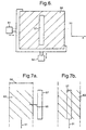
- a test rig for testing the astigmatic properties of a spinning mirror 50 comprising a laser 51 which generates a collimated laser beam 52, a focusing lens 53, a mirror mounting 54 driven by a motor 55, a screen 56 with a slit 57, a lens 58, a photodetector 59 and an oscilloscope 60.
- the screen 56 is located at the approximate focal point of the lens 53, i.e. the screen 56 is located at the same position as the interior of the rotating drum 1 ( Figure 1).
- the mirror 50 under test is illuminated by the beam 52 across its entire area: this gives a minimum diameter of the focused beam in the plane of the screen 56 (the larger the collimated screen the smaller the spot).
- Figure 6 is a plan view of the screen 56.
- the rectangular slit 57 has a length in the range 50-100 ⁇ m and a width in the range 3-4 ⁇ m. These values are chosen so that the width of the slit is approximately 30-50% of the minimum width of the beam in the plane of the slit 57, and so that the length of the slit is much greater than its width, giving sufficient discrimination between vertical and horizontal focus points.
- the width of the slit may be increased up to a maximum width which must be less than the maximum width of the focused beam (i.e. less than the long dimensions L x , L y of the spot 9 in Figure 2).
- the photodetector 59 has a sensitive area of approximately 1/4 mm diameter and has a uniform response across the sensitive area.
- the lens 58 is arranged such that photodetector receives light from an area with a diameter greater than the length of the slit 57. Therefore the photodetector 59 effectively integrates the intensity of the reflected light passing through the slit 57.
- the position of the screen 56 can be altered by an X micrometer 61 and a Y micrometer 62. A method of monitoring the distortion in the reflective surface of the mirror 50 is described below with reference to Figures 7 to 9.
- the beam sweeps out a path indicated at 63 in Figure 7.
- the beam has a width 58 having a maximum which is determined by the degree of astigmatism in the mirror 50, and a minimum (corresponding with the horizontal focus position) of the order of 10-12 ⁇ m (corresponding with a scanning resolution of 100 lines per mm).
- the beam is not aligned with the slit 57 (as illustrated in Figure 7a), and therefore the photodetector 59 detects no light.
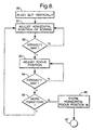
- the X micrometer 61 is adjusted (step 81) to move the slit 57 as illustrated at 65 until the slit 57 is positioned in the centre of the beam path 63, as illustrated in Figure 7b. In this position, the peak intensity of the light pulses received by the photodetector 59 are at a maximum (step 82).
- the X position of the slot can be adjusted until the slot 57 is approximately at the centre of the beam path 63.
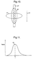
- the axial position of the lens 53 is then adjusted (step 83). This has the effect illustrated in Figures 10 and 11. With the lens 53 in the horizontal focus position f x , the peak light intensity I MAX passing through the slit 57 is at a maximum 23, shown in Figure 11 (corresponding with contour 20 shown in Figure 10). By monitoring the signal on oscilloscope 60 to determine the position of the maximum 23, the focal position f x can be approximately determined (step 84).
- steps 81-84 can be repeated, as indicated at step 85.
- the horizontal focus position f x is stored at step 86.
- the screen 56 is then rotated by 90° (step 88) so that the slit 57 lies horizontally as illustrated in Figure 12. If necessary, the horizontal position of the screen is adjusted using micrometer 61 (step 89) until the peak intensity I MAX is at a maximum (step 90). The focus position is then adjusted (step 91). In this case, the maximum amount of light passing through to photodetector 59 occurs when the lens 5 is in its vertical focus position, corresponding with contour 21 shown in Figure 12.
- the vertical focus position f y can be detected in the same way as the horizontal focus position, ie. by detecting a maximum in the peak pulse intensity I MAX received by the photodetector 59. However preferably the rise time of the signal on output line 66 is monitored, as discussed below.
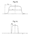
- Figure 13 is a graph of the intensity I of the light spot 9 along the X-axis when the lens 5 is in the vertical focal position (corresponding with contour 21).
- the spot has a length L y and a rise distance R L .
- Figure 14 is a graph of variation across the same contour 21 along the Y-axis. The maximum intensity is the same, but the width of the spot is S y and the rise distance is R s . As can be seen, R L is greater than R s . This feature is exploited in measuring the vertical focus position.
- Figure 15 is a graph illustrating the variation in the intensity I of light with respect to time t received by photodetector 59 during a single pulse, with the slit 57 arranged horizontally as shown in Figure 12.
- the signal is as illustrated at 70, with a high rise time t x (corresponding with R L ).
- the signal is as illustrated at 71, with a short rise time t y (corresponding with R s ).
- the vertical focus position f y is be determined.
- the difference (f x - f y ) between the axial positions of the lens 5 in the horizontal and vertical focus positions is then determined at 93. If this is greater than a predetermined maximum distortion value A max (step 94) then the mirror 50 is discarded at 95. Otherwise the mirror is acceptable (step 96) for inclusion in an imaging device.
- Figure 16 illustrates an alternative screen 80 to replace the screen 56.
- the screen 80 has a cross-shaped aperture 81. This enables the vertical and horizontal focus positions to be determined without having to rotate the screen between two positions.
- Figure 17 illustrates a further alternative screen 82 with a pair of horizontal and vertical slits 83,84 arranged at right angles in a T-shaped configuration.
- the screens 80,82 may be used in a method corresponding with Figures 8 and 9 (without the requirement of step 88), ie. the pulses from the slits may be used to determine the horizontal and vertical focus positions. Alternatively the astigmatism may be monitored by comparing the relative peak intensities from the two slits, as described below with reference to Figures 18-20.
- a first step 100 the screen 82 is adjusted vertically until the beam is aligned with the vertical slit. This can be detected when a pair of pulses can be seen (step 101).
- the axial position of the lens 53 is then adjusted (step 102) until the difference in peak intensity between the pair of pulses is at a maximum.
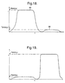
- the signal received by the photodetector with the screen 82 of Figure 17 and the lens in the horizontal focus position f x is illustrated in Figure 18.
- the photodetector receives a first pulse 85 from the vertical slit and a second pulse 86 from the horizontal slit.
- the difference between the peak intensity I max(x) of the first pulse and the peak intensity I max(y) of the second pulse is at a maximum and the difference I max(x) -I max(y) is indicative of the dynamic astigmatism.
- Figure 19 illustrates the signal with the lens 53 at the vertical focus position.
- I max(x) -I max(y) is at a minimum and is also indicative of the dynamic astigmatism.
- step 103 the difference I max(x) -I max(y) is calculated at 104 and used to determine whether the mirror is acceptable (steps 105-107).
Landscapes
- Physics & Mathematics (AREA)
- General Physics & Mathematics (AREA)
- Optics & Photonics (AREA)
- Photometry And Measurement Of Optical Pulse Characteristics (AREA)
- Length Measuring Devices By Optical Means (AREA)
Description
Claims (18)
- A method of monitoring distortion in a reflective surface of a spinning mirror, the method comprising:(1) spinning the mirror (50);(2) directing a beam of radiation (52) onto the reflective surface of the spinning mirror (50) to generate a reflected beam (64);(3) positioning a radiation detector (59) in the path of the reflected beam, (64), whereby the radiation detector (59) generates an electrical signal responsive to the shape of the reflected beam (64); and(4) monitoring the shape of the reflected beam (64) by monitoring the electrical signal generated by the radiation detector (59).
- A method according to claim 1 wherein steps (3) and (4) comprise(a) positioning an aperture (57) in front of the radiation detector (59) in the path of the reflected beam (64) whereby the detector (59) detects pulses of radiation from the reflected beam (64) which pass through the aperture (57); and(b) monitoring a characteristic of the detected radiation pulses.
- A method according to claim 1 or 2 further comprising(i) positioning a focusing optic (53, 58) in the path of the beam (52) or the reflected beam (64);(ii) varying and monitoring the optical distance between the focusing optic (53,58) and the radiation detector (59);(iii) detecting a horizontal focal point and a vertical focal point by monitoring variations in the electrical signal as the optical distance between the focusing optic (53,58) and the radiation detector (59) is varied; and(iv) determining a distortion value in accordance with the detected horizontal and vertical focal points.
- A method according to claim 2 or 3 wherein the monitored characteristic comprises the rise time of the detected radiation pulses.
- A method according to claim 2,3 or 4 wherein the monitored characteristic comprises the peak intensity of the detected radiation pulses.
- A method according to any of claims 2 to 5 wherein the monitored characteristic comprises the pulse duration of the detected radiation pulses.
- A method according to any of the claims 2 to 6 wherein the horizontal and/or vertical focal points are detected by detecting maxima and/or minima in the monitored characteristic.
- A method according to any of claims 2 to 7 wherein the aperture (57) comprises a slit.
- A method according to claim 8 wherein the reflected beam illuminates an area in the plane of the slit (57), and the slit (57) has a minimum dimension which is less than a maximum dimension of the illuminated area when the reflected beam (64) is focused on the slit (57).
- A method according to claim 8 or 9 when dependent on claim 3 comprising detecting the horizontal focal point with the slit (57) vertically aligned and detecting the vertical focal point with the slit (57) horizontally aligned.
- A method according to any of the preceding claims including at least claim 3 wherein step (ii) comprises varying the relative positions of the focusing optic (53,58) and the radiation detector (59).
- Apparatus for monitoring distortion in a reflective surface of a spinning mirror (50), the apparatus comprising:(1) a mirror drive (55) for spinning the mirror (50) ;(2) a radiation emitter (51) for directing a beam of radiation (52) in use onto the reflective surface of the spinning mirror (50) to generate a reflected beam (64);(3) a radiation detector (59) positioned in use in the path of the reflected beam (64), whereby the radiation detector (59) generates an electrical signal responsive to the shape of the reflected beam (64); and(4) means (60) for monitoring the shape of the reflected beam (64) by monitoring the electrical signal generated by the radiation detector (59).
- Apparatus according to claim 12 further comprising(a) a focusing optic (53,58) positioned in use in the path of the beam (52) or the reflected beam (64); and(b) an aperture (57) positioned in use in front of the radiation detector (59) in the path of the reflected beam (64) whereby the detector (54) detects pulses of radiation from the reflected beam (64) which pass through the aperture (57).
- Apparatus according to claim 13, further comprising means for varying and monitoring the optical distance between the focusing optic (53, 58) and the radiation detector (59).
- Apparatus according to claim 13, whereir the aperture is provided by a screen (80), the screen comprising a pair of non-parallel slits (83,84).
- Apparatus according to claim 15, wherein the slits (83,84) are arranged substantially at right angles to each other.
- Apparatus according to claim 15 or 16 wherein the slits are arranged in a cross-shape (81).
- Apparatus according to claim 15 or 16 wherein the slits (83,84) are arranged in a T-shape.
Applications Claiming Priority (1)
| Application Number | Priority Date | Filing Date | Title |
|---|---|---|---|
| PCT/GB1997/002381 WO1999012000A1 (en) | 1997-09-04 | 1997-09-04 | Monitoring distortion of a spinning mirror |
Publications (2)
| Publication Number | Publication Date |
|---|---|
| EP0935735A1 EP0935735A1 (en) | 1999-08-18 |
| EP0935735B1 true EP0935735B1 (en) | 2005-01-12 |
Family
ID=10807160
Family Applications (1)
| Application Number | Title | Priority Date | Filing Date |
|---|---|---|---|
| EP97939035A Expired - Lifetime EP0935735B1 (en) | 1997-09-04 | 1997-09-04 | Monitoring distortion of a spinning mirror |
Country Status (5)
| Country | Link |
|---|---|
| US (1) | US6154304A (en) |
| EP (1) | EP0935735B1 (en) |
| JP (1) | JP2001504594A (en) |
| DE (1) | DE69732241T2 (en) |
| WO (1) | WO1999012000A1 (en) |
Families Citing this family (1)
| Publication number | Priority date | Publication date | Assignee | Title |
|---|---|---|---|---|
| US7316356B2 (en) * | 2005-09-01 | 2008-01-08 | Ncr Corporation | Optical scanner having a balanced mirrored spinner |
Family Cites Families (3)
| Publication number | Priority date | Publication date | Assignee | Title |
|---|---|---|---|---|
| US3743427A (en) * | 1971-06-29 | 1973-07-03 | Weiser Robodyne Corp | Modulation transfer function measurement system and method |
| GB1598648A (en) * | 1978-05-26 | 1981-09-23 | Sira Institute | Method of determining a characteristic of an optical component |
| US5535042A (en) * | 1993-06-17 | 1996-07-09 | Fuji Photo Film Co., Ltd. | Light scanning device |
-
1997
- 1997-09-04 JP JP51639499A patent/JP2001504594A/en not_active Ceased
- 1997-09-04 WO PCT/GB1997/002381 patent/WO1999012000A1/en not_active Ceased
- 1997-09-04 US US09/284,738 patent/US6154304A/en not_active Expired - Fee Related
- 1997-09-04 EP EP97939035A patent/EP0935735B1/en not_active Expired - Lifetime
- 1997-09-04 DE DE69732241T patent/DE69732241T2/en not_active Expired - Fee Related
Also Published As
| Publication number | Publication date |
|---|---|
| DE69732241D1 (en) | 2005-02-17 |
| EP0935735A1 (en) | 1999-08-18 |
| JP2001504594A (en) | 2001-04-03 |
| WO1999012000A1 (en) | 1999-03-11 |
| US6154304A (en) | 2000-11-28 |
| DE69732241T2 (en) | 2005-12-29 |
Similar Documents
| Publication | Publication Date | Title |
|---|---|---|
| JP2790279B2 (en) | Particle detection method and device | |
| US5159412A (en) | Optical measurement device with enhanced sensitivity | |
| EP0500293B1 (en) | Particle detection method and apparatus | |
| US5576831A (en) | Wafer alignment sensor | |
| US4417149A (en) | Apparatus for detecting and measuring defects | |
| US5210592A (en) | Method and apparatus for determining the optical quality of a transparent plate | |
| JPH06112106A (en) | Object image focusing device and method, and mask image focusing device | |
| US5070237A (en) | Optical measurement and detection system | |
| US5083035A (en) | Position location in surface scanning using interval timing between scan marks on test wafers | |
| JP3105702B2 (en) | Optical defect inspection equipment | |
| US3418477A (en) | Apparatus for determining the focal point of a light beam | |
| US4097160A (en) | Method for inspecting object defection by light beam | |
| JP2842310B2 (en) | Optical module optical axis adjusting apparatus and method | |
| US6154304A (en) | Monitoring distortion of a spinning mirror | |
| CA2282015C (en) | Light-scanning device | |
| CN110799816B (en) | Measuring probe for beam scanning | |
| JP2531449B2 (en) | Laser displacement meter | |
| JPH06102028A (en) | Optical non-contact distance measuring machine and measuring method | |
| JP2531450B2 (en) | Laser displacement meter | |
| US6618131B1 (en) | System and method for measuring the quality of an illumination field from a laser line illumination system | |
| JP3470729B2 (en) | Method and apparatus for measuring refractive index distribution | |
| JP3222214B2 (en) | Target surface position detection device | |
| JPH09257643A (en) | Lens meter | |
| JP3009070B2 (en) | Optical scanning measurement device and measurement method | |
| GB2124761A (en) | Measuring position and/or dimensions of objects |
Legal Events
| Date | Code | Title | Description |
|---|---|---|---|
| PUAI | Public reference made under article 153(3) epc to a published international application that has entered the european phase |
Free format text: ORIGINAL CODE: 0009012 |
|
| AK | Designated contracting states |
Kind code of ref document: A1 Designated state(s): DE GB |
|
| 17P | Request for examination filed |
Effective date: 19990524 |
|
| 17Q | First examination report despatched |
Effective date: 20040226 |
|
| GRAP | Despatch of communication of intention to grant a patent |
Free format text: ORIGINAL CODE: EPIDOSNIGR1 |
|
| GRAS | Grant fee paid |
Free format text: ORIGINAL CODE: EPIDOSNIGR3 |
|
| GRAA | (expected) grant |
Free format text: ORIGINAL CODE: 0009210 |
|
| AK | Designated contracting states |
Kind code of ref document: B1 Designated state(s): DE GB |
|
| REG | Reference to a national code |
Ref country code: GB Ref legal event code: FG4D |
|
| REF | Corresponds to: |
Ref document number: 69732241 Country of ref document: DE Date of ref document: 20050217 Kind code of ref document: P |
|
| PLBE | No opposition filed within time limit |
Free format text: ORIGINAL CODE: 0009261 |
|
| STAA | Information on the status of an ep patent application or granted ep patent |
Free format text: STATUS: NO OPPOSITION FILED WITHIN TIME LIMIT |
|
| 26N | No opposition filed |
Effective date: 20051013 |
|
| PGFP | Annual fee paid to national office [announced via postgrant information from national office to epo] |
Ref country code: GB Payment date: 20060830 Year of fee payment: 10 |
|
| PGFP | Annual fee paid to national office [announced via postgrant information from national office to epo] |
Ref country code: DE Payment date: 20060831 Year of fee payment: 10 |
|
| GBPC | Gb: european patent ceased through non-payment of renewal fee |
Effective date: 20070904 |
|
| PG25 | Lapsed in a contracting state [announced via postgrant information from national office to epo] |
Ref country code: DE Free format text: LAPSE BECAUSE OF NON-PAYMENT OF DUE FEES Effective date: 20080401 |
|
| PG25 | Lapsed in a contracting state [announced via postgrant information from national office to epo] |
Ref country code: GB Free format text: LAPSE BECAUSE OF NON-PAYMENT OF DUE FEES Effective date: 20070904 |